
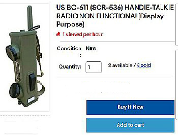
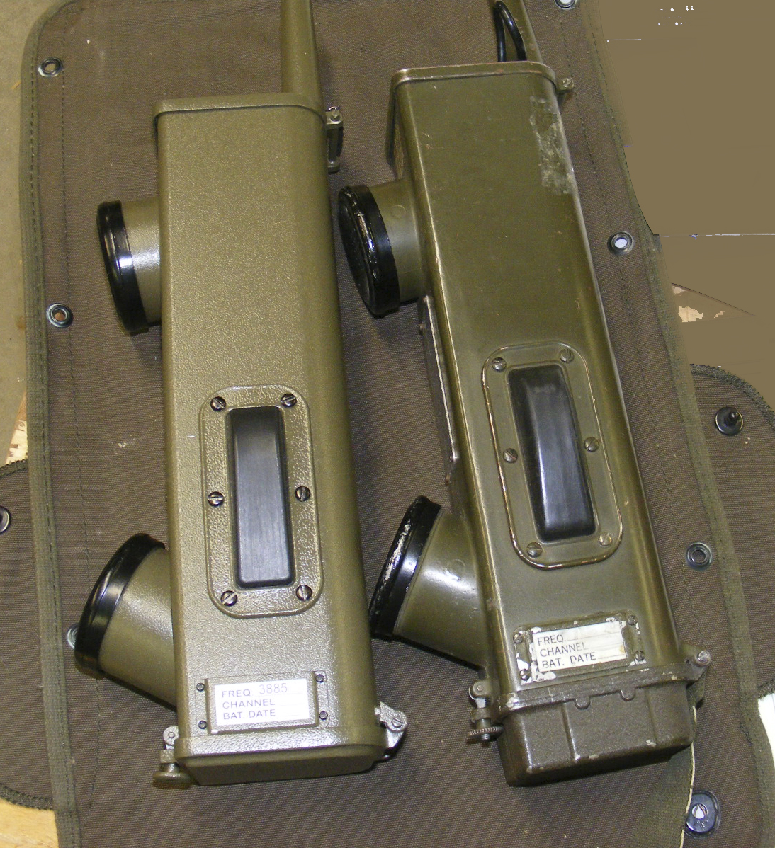
Assemble a solid state "Display" radio using OTS DIY kits mounted inside a imported BC-611 display case (Empty shell option).
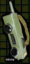
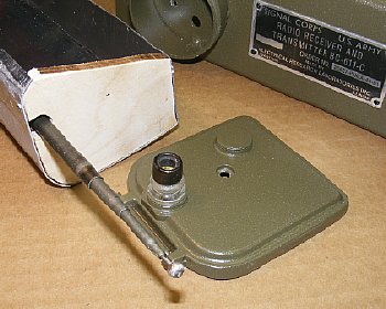
"Display
Radio Case" shown with mic and earphone caps removed.
Click
to enlarge
A "solid state" BC-611 Knockoff in a "Imported Case".
Use
economy DIY kits to built a AM transceiver on 3885 kcs.
 This
project may require some experimentation with a audio and RF antenna
circuit as well as assembling DIY kits. Those with a "Winding Coil
Phobia" or those hesitant to heat up a soldering iron might consider
another project.
This
project may require some experimentation with a audio and RF antenna
circuit as well as assembling DIY kits. Those with a "Winding Coil
Phobia" or those hesitant to heat up a soldering iron might consider
another project. Q. Why does a project start off simple and then expand into a larger more complex project?
Click to enlarge
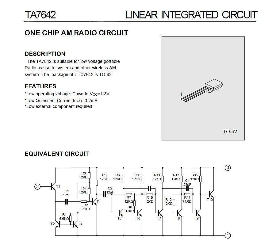
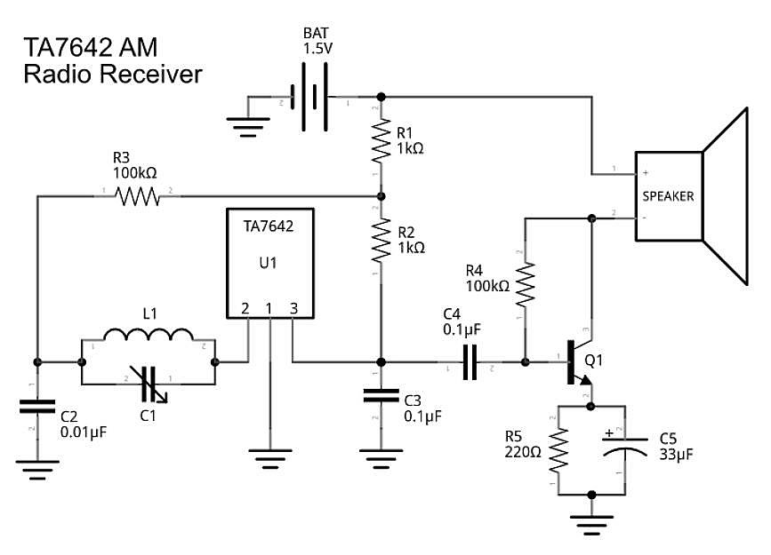
The original plan was to use a TA7642 (revised MK484) integrated circuit in a simple receiver and feed it to a vehicle installed (M151A) radio audio amplifier and let that audio amp do dual duty.
Click
to enlarge
The
TA7642 IC can be utilized as the basis for a fairly simple receiver and
is rated for use up to 3 Mcs.
Click
to enlarge
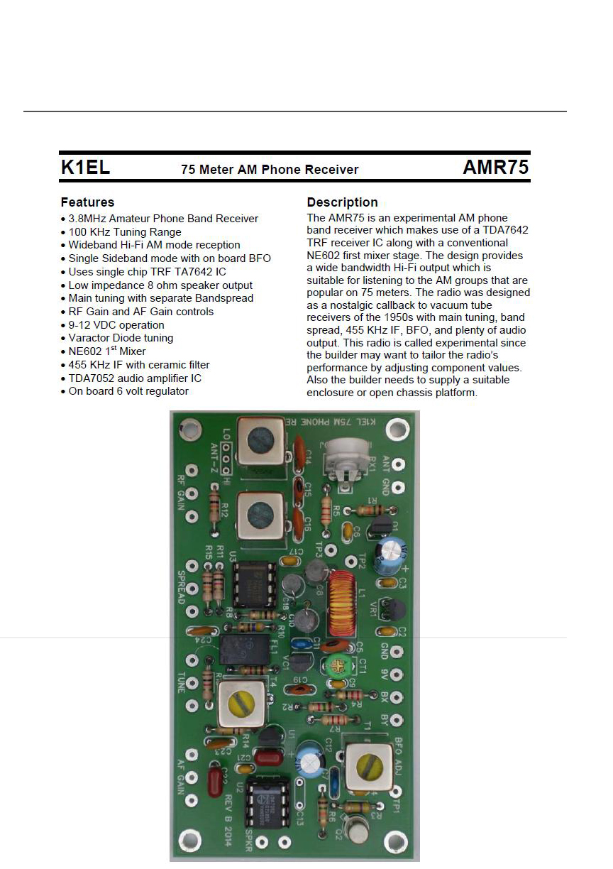
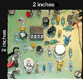
While
searching for TA7642 IC circuits I found several receiver DIY kits. This
K1EL receiver kit was perfect and utilizes the 7542 IC. So why bother
with copying and constructing a circuit when a kit complete with a small
PC board was available. The kit has varactor variable tuning, BFO, RF
gain etc. The board measure 3.9 inches by 2.1 inches. The receiver has
great utility and can be utilized on AM (with carrier) , SSB, and CW.
Q.
Why does a project start off simple and then expand into a larger more
complex project?
Click
to enlarge
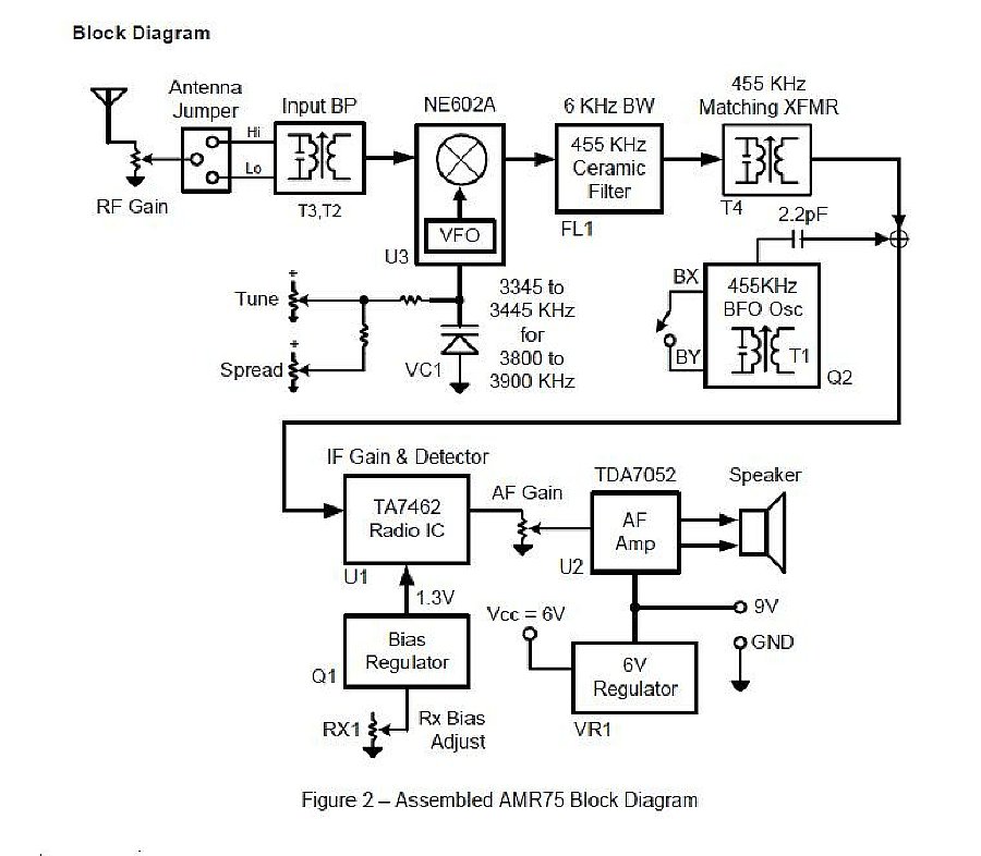
Block diagram of the receiver.
The
"original plan" was to build a simple receiver and just stuff
it into a small enclosure.
Q. Why does a project start off simple and then expand into a larger more complex project?
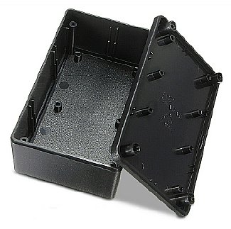
Several years ago I queried the overseas company WPG International about a empty case and purchased one for a very reasonable price, perhaps it was a unit that did not pass final inspection etc. Today the "empty shells are advertised as available but the price is higher. Now you can order the case with a FRS radio or a empty shell.
Q. Why does a project start off simple and then expand into a larger more complex project?
My imported "empty" case that I ordered several years ago had Phillips screws so I replaced them with slotted screws. Later model display cases had slotted screws.
A
project decision was made to house a receiver and include a companion
transmitter. Plenty of room inside the "Imported Display Case"
for a small receiver and transmitter DIY kits as well as batteries.
Q. Why does a project start off simple and then expand into a larger more complex project?
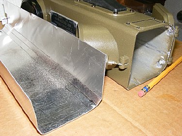
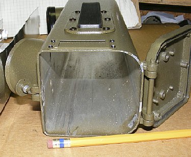
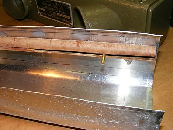
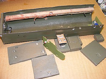
An "open" chassis tray was bent to fit inside the shell. I used .050 aluminum. Use a vice with wood blocks to bend the aluminum.
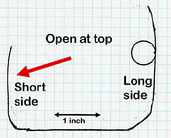
Actual
end view outline of my chassis tray. The bends are not perfect but close
enough for government work.
One chassis side is shorter in height to allow wiring to the microphone and earphone cups as needed.
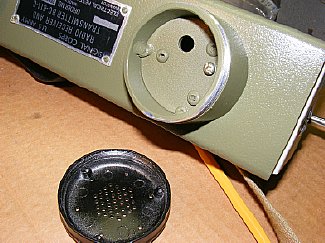
A
small hole was drilled in the microphone compartment for wiring. The round
exterior compartments are threaded and the caps are easily removed,
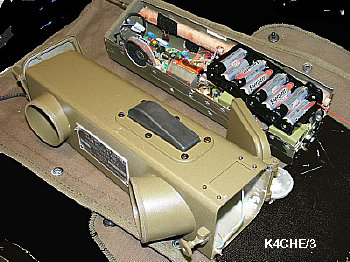
The typical QRP "Pixie" transmitter will easily fit in the U shaped chassis. The kits are very cheap and several different versions are available on ePay.
Click to enlarge
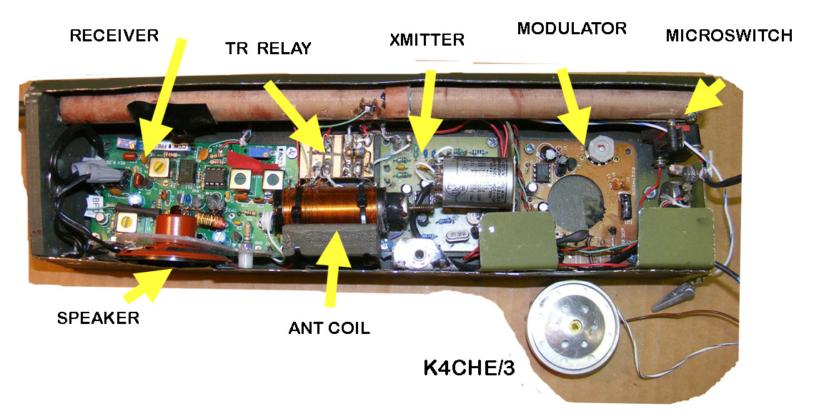
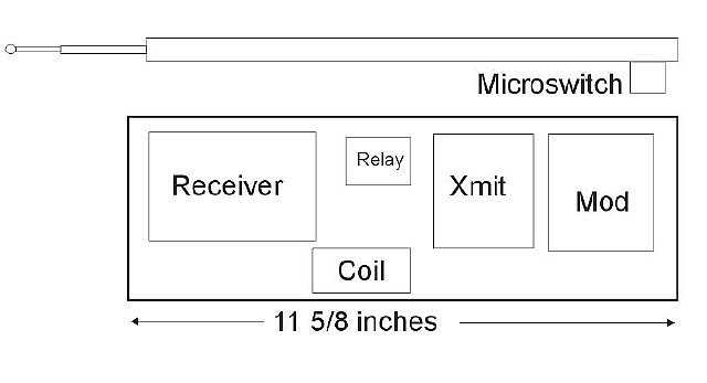
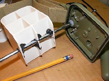
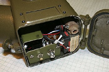
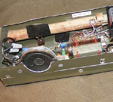
Basic chassis componet layout for the K4CHE BC-611 Knockoff radio.
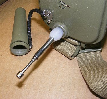
The "antenna" on the imported case only extends 17 inches and looks weird. Later models of the display case has slightly longer antennas. The insulator is soft rubber. It all had to go. More info below
The original antenna base is glued to the plastic cube.
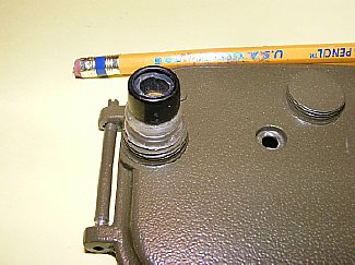
A replacement antenna insulator that I purchased from WA5CAB was installed. You can also fabricate a insulator using a miniature plumbing fixture. The insulator housing is not threaded - your replacement insulator will have to be sized and glued in pace.

A Garolite tube was used for the antenna guide. A slot was cut halfway up the tubing for the antenna guide bolt. The bolt activates the ON-OFF microswitch when the antenna is collapsed. "GOOP" was used to attach the tube to the side of the chassis.
Garolite is a strange magic material composed of fiberglass-epoxy laminate material. It is very rugged and easy to cut or shape. Order from McMaster-Carr.
Slotted antenna tube. The 6-32 bolt is attached to the bottom of the antenna.

"GOOP" was used to attach the antenna guide tube to the chassis. Small holes were drilled in the chassis under the tube to provide solid attachment points for the Goop.
I used a resurrected BC-611 antenna that could not be used in the antenna channel of a actual radio as it was bent beyond repair. WA5CAB may have some antennas. A piece of "aircraft" plywood was fitted to the "Top" end of the chassis.
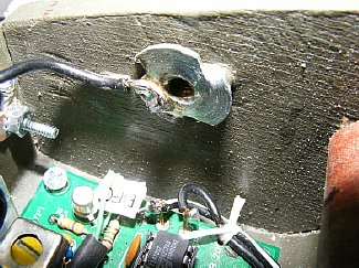
A "T" nut was installed in the plywood end for attaching the top cap of the radio. The "T" nut is grounded to the chassis and provides a good RF ground for the top of the display case. A portion of the receiver circuit board is shown.
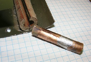
A section of a copper tube was sized and inserted into the tube and used for the antenna contact. It was pre-tinned for a later connection for the lead to the TR relay.
A notch is cut in
the center of the Garolite tube and the antenna lead soldered on.
The coils shown
were used as test coils for determing the approximate inductance to match
the antenna. More info below.
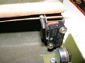
A 6/32 bolt was attached to the base end of the antenna and covered with heat shrink and activates the "ON-OFF microswitch when the antenna is collasped. Later a "Stop" for the antenna rod was installed to prevent bending the thin microswitch lever.
A antenna mechanical "Stop" was installed to prevent bending the thin microswitch lever when the antenna is collapsed.
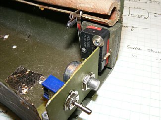
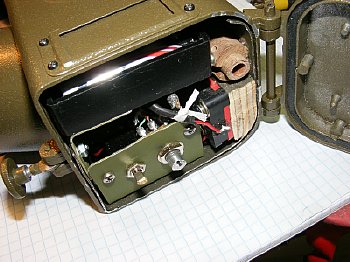
A bracket was installed for a Master ON OFF switch and a small pot for "fine" tuning the receiver. The microswitch was mounted on a small piece of plywood.
The control bracket can be accessed by opening the radio door. The microswitch is mounted below the antenna tube on a small wooden block.
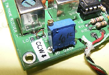
The large pots that were supplied with the receiver were replaced with miniature 10 turn resistors. Once the volume or gain etc. is set there was no need for further external adjustment. Exception: a small "Fine Tuning" pot was wired to the board and installed on the control bracket at the bottom of the chassis.
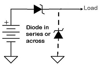
![]() When
assembling your DIY kit tray insert a diode in series or across the battery
line for reverse polarity protection. The kits are usually produced with
minimum parts due to cost and usually do not provide any sort of protection.
A schottky diode is shown (low voltage drop) but if you do not have one
available use a normal silicon diode with proper current rating. This
will save you from those little wiring mistakes.
When
assembling your DIY kit tray insert a diode in series or across the battery
line for reverse polarity protection. The kits are usually produced with
minimum parts due to cost and usually do not provide any sort of protection.
A schottky diode is shown (low voltage drop) but if you do not have one
available use a normal silicon diode with proper current rating. This
will save you from those little wiring mistakes.
These plywood pieces were used to mount the various kit boards. The wood provides good insulation from the chassis and allow easy access or removal of the boards which are held in place with small wood screws. KISS
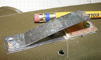
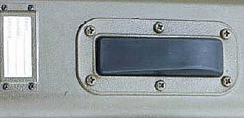
The PTT switch was constructed using a section of "Hose Clamp" strap and a small piece of circuit board. A spring was added to give the the correct feel when the radio rubber switch cover is installed. The end of the switch is grounded to the chassis via the 4-40 mounting bolt. The small piece of circuit board at the other end serves as a contact and will be connected to the high side of the PTT relay coil.
Click
to enlarge
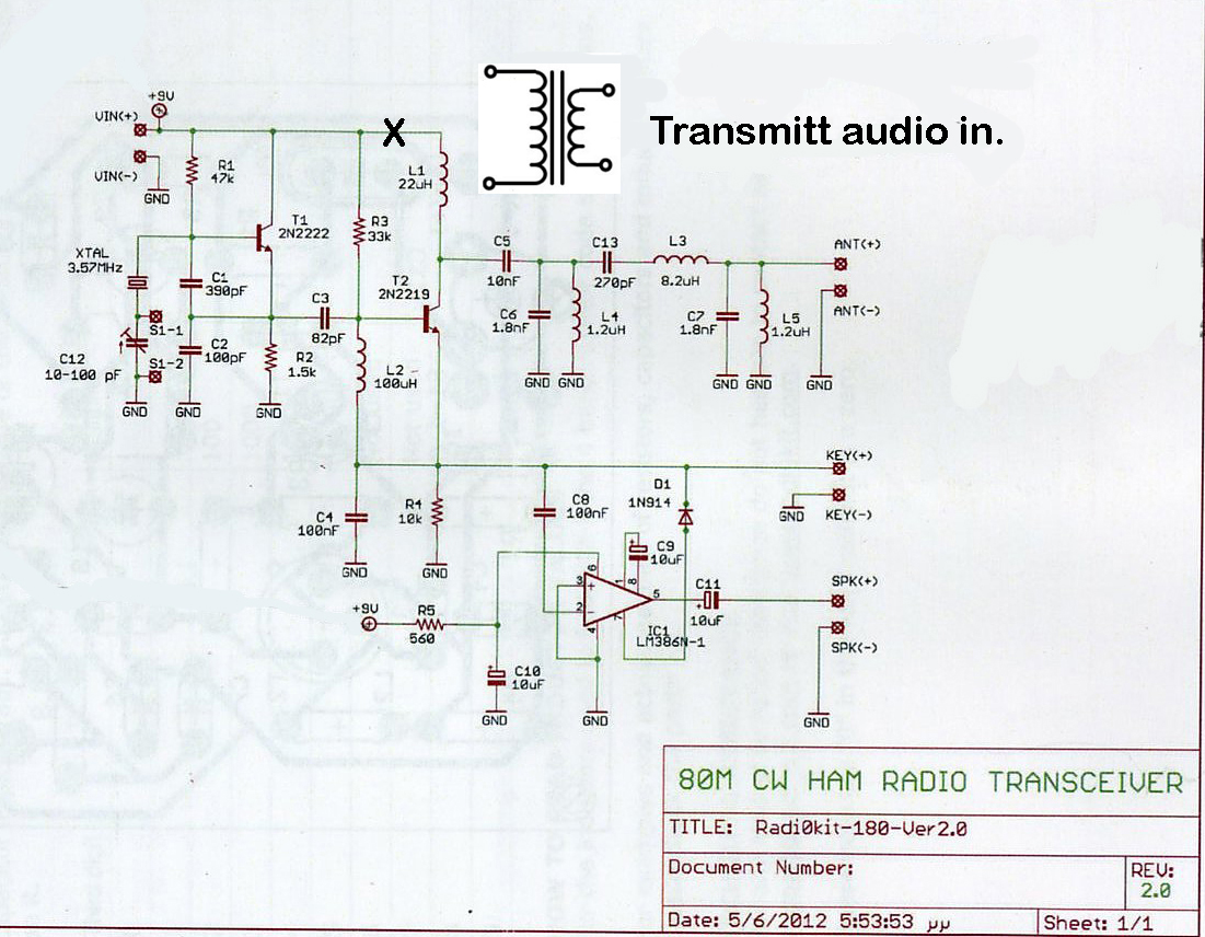
The Pixie will be modified for modulation by inserting a transformer in series with the collector Battery voltage line prior to the choke (L1) in the amplifier.
I only used the transmitter portion of the Pixie board. The "Direct Conversion Receiver" section was not used.
![]()
Q. Will BC-611 "Knockoff" cover 3570 kcs also?
A. Yes, just change the crystal and move the tap on the Ant Coil.
Q. Why not just use the "Pixie" receiver with an additional audio amplifier?
A.
I wanted a more selective receiver that was tunable and suitable for AM
with carrier.
Q. Why
not use some sort of phase modulation that would require less audio?
Q. I tried a couple of circuits but was not happy with the audio.
Q. Why not use isolate the LM386 audio amplifier IC in the Pixie circuit and use that IC as a modulator?
A. Good idea but not enough audio. However you could isolate and use this audio stage to drive an additional audio amp IC and have enough audio to drive the modulation transformer.
Q. Maybe use the LM386 on the pixie board to to provide "Sidetone" during transmit?
A. Good idea - I may try it.
![]()
Several
types of "Modulation Transformers" were tested. Wall wart transformers
worked depending on the voltage and the secondary resistance. Small AC
filament transformers were also tested. The objectives when selecting
a transformer are:
a. Select a transformer that has a secondary winding that is low in resistance. The transformer secondary is in series with the battery and the winding resistance of the secondary will lower the voltage to the collector of the final amplifier transistor.
b. Select a transformer that suits your audio input level.
c.
Select a transformer that will fit your chassis.
I installed a heat sink on the final transistor. The 2N2219 transistor in my kit was rated at 800 mW but got fairly warm when transmitting for 30 seconds and tuning up the antenna. My modulated output was a little over 400mW to 500 mW depending on the battery voltage. The modulation transformer secondary resistance in the collector lead reduces the voltage to the collector. More info below.
![]()
Do
not keep the transmitter keyed for extended periods.

There are a lot of different "clamp on" heat sinks.
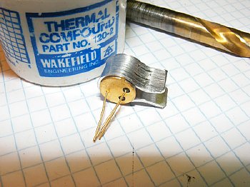
Its easy to fabricate a heat sink using a .050 aluminum strip bent around a drill bit and clamped in a vise. Apply a small amount of thermal compound.
Click
to enlarge
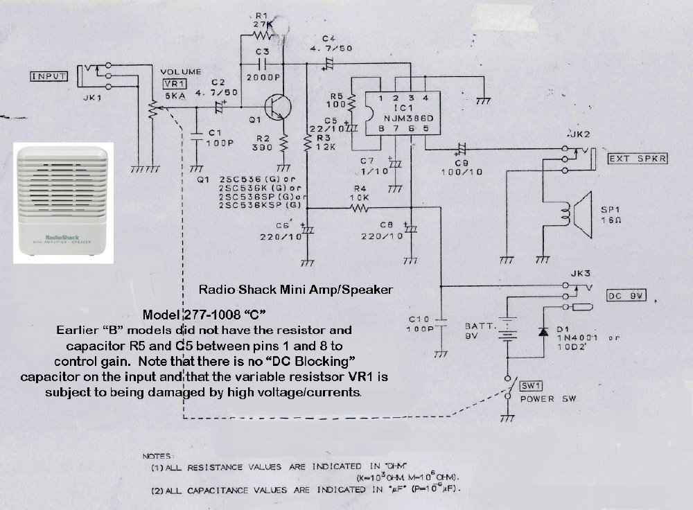
A Radio Shack miniature speaker amplifier was used for the "modulator". It provided plenty of audio. Note that it has a small preamp stage prior to the LM386.
The Radio Shack "Mini Audio Amplifier" circuit board was removed from its housing and was easily mounted in the chassis. The fixed gain control circuits and volume control were left intact. The small "modulation" transformer (my second choice) is on the left and is mounted over the transmitter.
![]()
My second transformer was a UTC "Ouncer" . I used the low ohmage taps.

A
vertical shield was used between the modulator and transmitter. The shield
came in handy for mounting the modulation transformer. The small Pixie
radio (transmitter) has not been attached to its wooden pad yet.
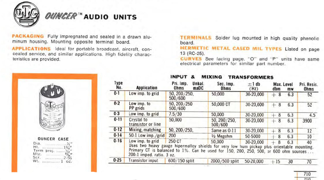
I
utilized the UTC O-12 "Ouncer" transformer as it was in my junk
box.
A GE element was used for the microphone input to the modulator. The element has high output and easily fits inside the radio microphone cup. Old GE mobile mics can be found at a hamfest for a buck. You have to "Hanz" the boxes under the tables.
![]()
Q. I don't have that element. Will a electret mic element circuit work?
A. Yes but you will need a preamp.
Q. Can I use a carbon microphone button telephone type?
A. Good idea
but I did not try it. Carbon microphone circuits have high output and
are simple.
A standard telephone button will fit inside the microphone cup but
you may have to remove the outter rim. Details at:
http://k4che.com/T-17/T-17.htm
The
microphone element was mounted in the cup on the outside of the case and
is accessible by unscrewing the cup cap. I used simple wire nuts for connections
for easy disconnect when the chassis has to be removed from the case.
CLICK
to enlarge
The TR Relay and ANT coil will be discussed next. The speaker remains on the chassis but the microphone is mounted in the exterior cup.
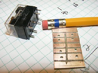
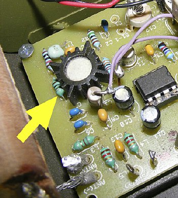
Pick a relay with low current draw. I fabricated a small PC board for connections.
The 6 volt relay was a DPDT. One set of contacts for the antenna change over and the other set was utilized for battery power transfer between the transmitter and receiver.
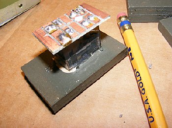
The ANT coil was mounted to a 1/4 inch piece of aircraft plywood. The CW jack is on the left. Slug tuning was used on this coil as well as various taps. More info below.
Click
to enlarge
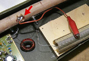
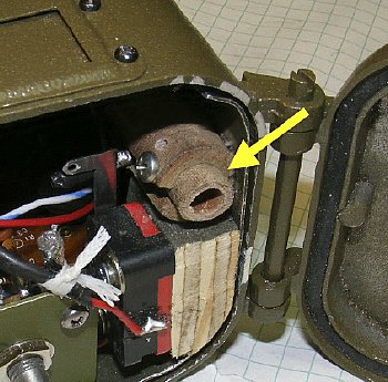
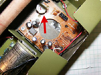
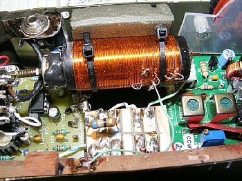
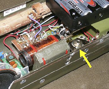
Relay
assembly glued to a small piece of plywood and mounted on the left. Antenna
coil and plywood mount on the right. Red cable ties.
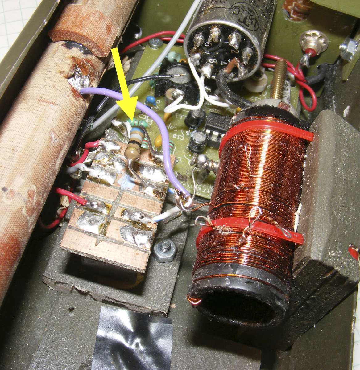
A 65
ohm resistor (yellow arrow) was added in series with the relay coil to
reduce current draw. The relay was drawing more current than the transmitter!
![]()
Q. Why not just use pin diodes for the switching?
A. Good idea. But to keep it simple I just used a relay.
Q. How about a wiring schematic for the relay.
A.
The relay has two sets of contact and is a DPDT. One set of contacts switches
the antenna from receive (NC) to transmit. The Other set of contact switches
the 12 volt battery pack from receive (NC) to transmit.
First
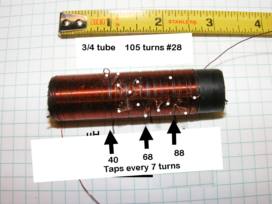
Coil for testing. Click to enlarge.
The first coil.
105 turns #28 on a PVC 3/4 inch form. The inductance needed for resonating
the whip antenna was approximately 50-55 uH (On the coil above a tap close
to 50 uH would be located near the center) based on using my Pixie circuit
with a fixed output circuit which is shown below. Numerous taps help you
find resonance. Easiest method for tuning is to monitor F.S. (Field Strength)
but it is best to monitor F.S. and observe collector current for a dip.
![]()
Q. Do I have to go outside to tune the antenna coil?
A. No just extend the antenna and try to keep clear of nearby objects. Initially place the "Simple FS Meter" about 6 inches from the antenna to find the approximate Tap on the Ant Coil. Then move the FS meter further away to fine tune.
Q. Will a coil value of 50-55 uH match my Pixie transmitter?
A. Depends on the values used in your Pixie output stage. Multiple taps on the coil should help you find a match.
Q. Your PVC pipe is black. Where did you get it?
A.
Irrigation section of your local store.
Q. I don't have a "Simple" FS meter.
A.
Build one. Or perhaps find a ME-61 on ePay. Link
below.
Q.
I hate winding coils.
A. You and many others, perhaps group therapy?
Information on simple FS meters and tuning can be found here:

1.8
nF = 1800pf = 1800mmfd = .0018uF
A typical transmitter output stage used on a Pixie QRP transceiver.
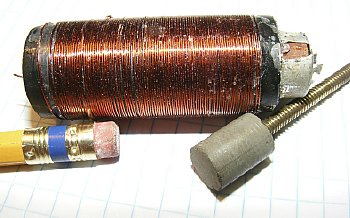
Experimenting with a ferrite slug allowed some really precise tuning. The slug created a change in inductance of 5 to 8 uH. However "tap tuning" was more than adequate.
 When tuning for resonance monitor Field Strength and collector current.
You should experience a peak in Field Strength at the same time you obtain
a dip in collector current. Expect a 20 Ma dip in collector current -
on my Pixie Kit current would vary between 85 mA at resonance and
115 mA out of resonance. An easy way to monitor for resonance is just
monitor the total system current. With a TR relay installed the current
may be around 150-200 mA depending on the relay coil and a definite dip
of approximately 20 Ma can still be observed.
When tuning for resonance monitor Field Strength and collector current.
You should experience a peak in Field Strength at the same time you obtain
a dip in collector current. Expect a 20 Ma dip in collector current -
on my Pixie Kit current would vary between 85 mA at resonance and
115 mA out of resonance. An easy way to monitor for resonance is just
monitor the total system current. With a TR relay installed the current
may be around 150-200 mA depending on the relay coil and a definite dip
of approximately 20 Ma can still be observed.
![]() It
is possible to receive RF burns while tuning. Unkey when changing taps.
The voltage can be high enough to light a small florescent bulb.
It
is possible to receive RF burns while tuning. Unkey when changing taps.
The voltage can be high enough to light a small florescent bulb.
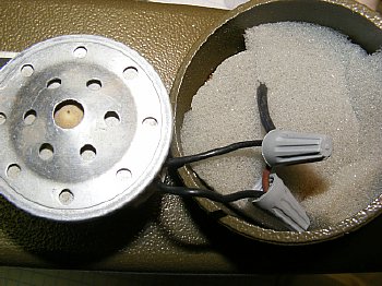
The
speaker was mounted on the side of the chassis with a piece of scrap plastic.The
receiver audio can easily be heard through the imported case ear piece
cup as I drilled a hole in it.
I
installed a miniature CW keying jack with normally closed contacts. This
allowed easy monitoring of collector current as well as having the ability
to key the set when operating on CW on 80 meters. When the plug is removed
the keying circuit is closed for AM (with carrier) operations.
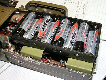
Plenty of room for a AA battery pack. Side brackets support the pack.
It's
easy to remove the battery pack. Master ON/OFF switch and receiver Fine
Tuning control are shown.
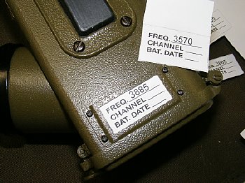
As
a final touch a FREQ card was inserted into the holder.
CLICK
to enlarge
FINI
- A working display copy of the BC-611. Twice the output power and a really
nice receiver.