| BC-611 Transmitter Bench Ops Rev 11-12-20 |
 This web page series on the BC-611 contains information
and techniques dedicated to the BC-611 transmitter. This web page assumes
that the reader has possession of TM 11-235. Photos and descriptions pertain
usually to the "F" model however the majority of the information
can be applied to earlier A-E models. The BC-611 receiver will be covered
in another document including info on IF coils.
This web page series on the BC-611 contains information
and techniques dedicated to the BC-611 transmitter. This web page assumes
that the reader has possession of TM 11-235. Photos and descriptions pertain
usually to the "F" model however the majority of the information
can be applied to earlier A-E models. The BC-611 receiver will be covered
in another document including info on IF coils. And I apologize in advance if some of my adaptations or mods offend those that want a "perfect" radio. My goal is to move the radio off the shelf and into operation.
 Index
Click to Navigate
Index
Click to Navigate
Bench
Power
Antenna
Coil Modification
Final
Amplifier Tuning
Test
Case for Alignment
Transmitter
power test #47 bulb
Pogo
Stick BC-745 Coil Info
Microphone
Replacement
Battery
Inverter Info
Misc
Bench Power
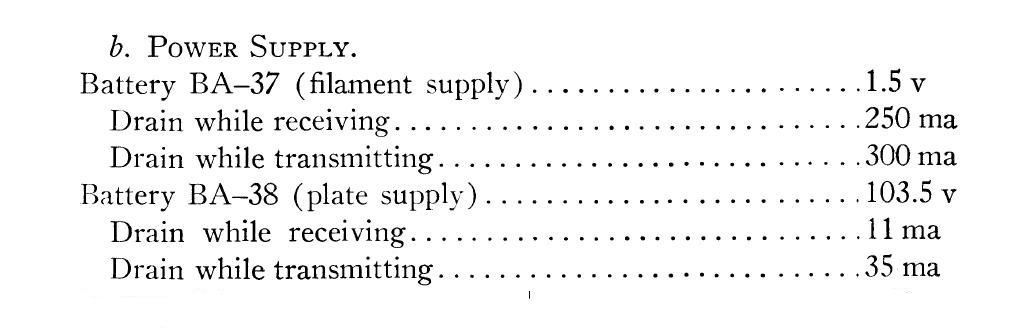
Voltage and Current required. Click to enlarge
 High voltage is present on the BC-611 chassis.
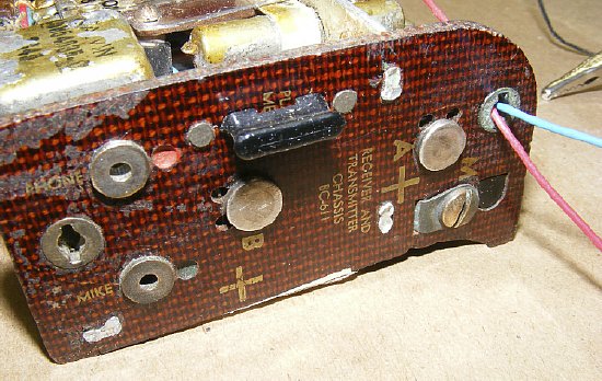
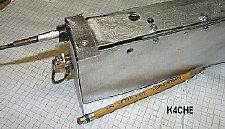
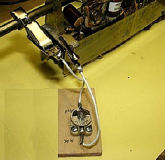
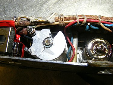
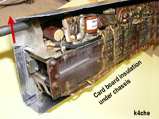
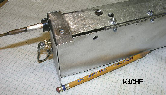
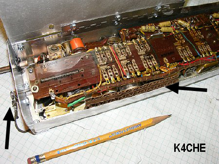
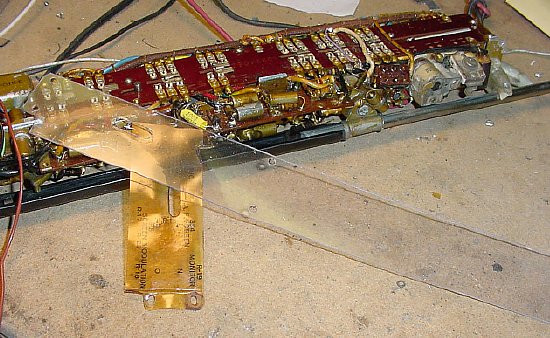
The external power leads can be fed through openings in the terminal board to facilitate inserting the radio chassis into the case while being powered externally for testing. Do not solder wires directly to the battery contacts. Note that the Plate Current Meter Plug (Jumper) is in place.
The junction of R22 and R22 can be used to feed the B plus buss. Note that the plate current meter jack on the bottom right has a "internal" jumper installed as the original jumper was removed and put aside until final assembly.

R21 and R22 junction.
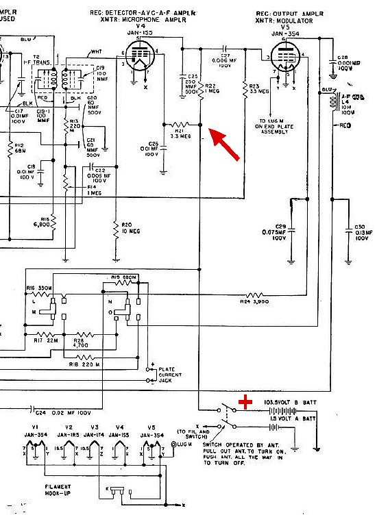
The junction of R21 and R22 is on the main B plus line after the ON - OFF switch and provides High Voltage to the entire radio.
Transmitter B +
The Plate Current jack plug and the "Receiver" L2 coil need to be in place to provide B+ to the transmitter. When testing the transmitter L2 does not have to be in the exact frequency range and is tuned only during receive. More info on the L2 coils will be presented in the Receiver Section of this series.
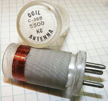
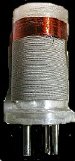
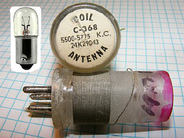
BC-611 L1 ANT COILS that are designed for the higher frequency channels can be modified for use on 75 Meters. The coil shown above for 5,500 KC is now on 3.885 kc. Just add turns. Additionally BC-745 (Pogo Stick) coils which are similar can also be modified by adding turns. More info below.
 Winding ANT Coils for 3885 KC
Q.
There are plenty of 3885 C360 coils on ePay so why bother with a modification
of a higher frequency coil?
A.
Good luck with your search.
Q.
Can I modify other BC-611 coils other than the 5500 kc?
A.
Yes. The lower frequency coils in the 4 Mc range are actually easier to
modify as they require less turns. Pogo Stick coils can also be modified.
More info on Pogo coils below.
Q.
My coil is for 3590 KC (C358) do I add turns?
A.
No you will have to remove turns. That coil is sort of rare and I would
rather save it.
Q.
Where do I find enamel covered wire?
A. ePay or liberate enamel wire by removing wire from a relay or IF coil.
Q. I hate winding coils. Will you wind one for me?
A.
No. Just give it a try as it is not Rocket Science. Its just a small additional
winding added to a existing winding in series - sometimes only 20-25 turns
depending on the frequency range of the original coil. The 4 Mc coils
require less additional windings than the higher frequency 5 Mc coils.
The additional winding does not have to be perfect and can even overlap
a turn or two or have spaces. More info below.
Q.
The coil is sealed - how do you remove the outer cover?
A.
Its PFM ![]() more info below.
more info below.
Q. The wire for the additional winding in the above photo is obviously a smaller gauge than the original wire? Will that effect the "Q" of the coil?
A. Yes, slightly. However you will never be able to measure the difference in the power output (efficiency) of the Power Amplifier.
Q. How will I know if I have added the correct number of turns?
A. Several ways. Watch for resonance (dip) on plate current. Watch for a peak on a simple field strength meter. Grid dip the coil. More info below.
Q. What size wire should I use?
A. I used #34 - I would not use any smaller wire than #34 as it will break. Try wire sizes in the 30's or upper 20's. If the wire is too large you may not have enough room on the form for the required additional turns.
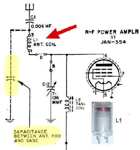
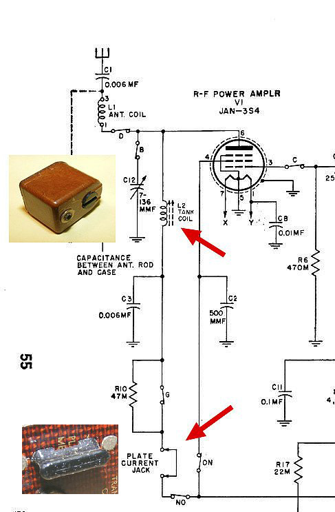
The plug in coil L1 is part of the output tuning for the final R-F amplifier. The tuning circuit is a Pi-Network and uses the small amount of capacitance created between the antenna rod and the outer case as the "Loading Capacitor".
 Discussion
of this "Loading Capacitor" and a substitute circuits
for bench testing will be presented below. In other words we will create
the artificial capacitance on the bench and then be able to tune up, dip
the final, and measure the RF output of the set without inserting the
radio into the case.
Discussion
of this "Loading Capacitor" and a substitute circuits
for bench testing will be presented below. In other words we will create
the artificial capacitance on the bench and then be able to tune up, dip
the final, and measure the RF output of the set without inserting the
radio into the case.
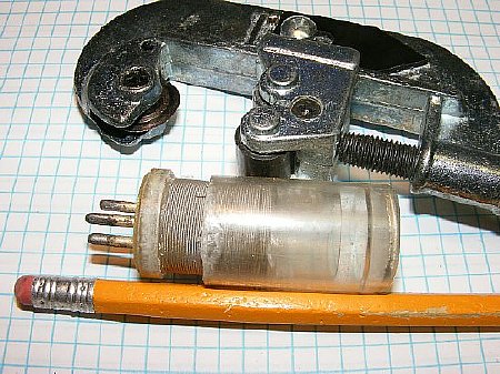
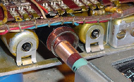
A
tubing cutter can be used to open the coil form.
Note
that the coil shown above has a winding that extends all the way to the
bottom so cut carefully and do not cut too deep. Examine your coil and
determining where the top of the base is. Cut approximately 3/16 inch
from the bottom.
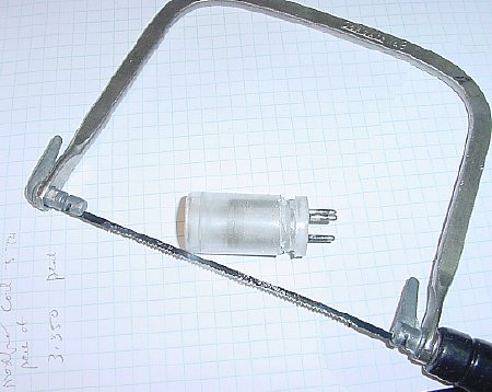
Not as neat but a coping saw will work.
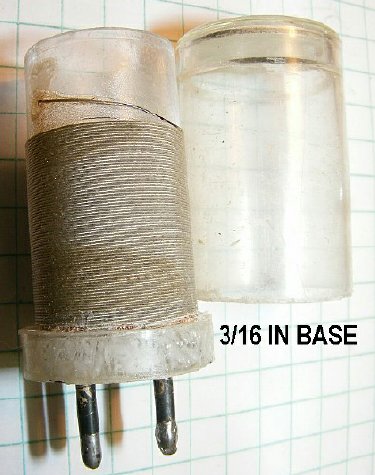
When removing the outer cover some coils have windings that start near the base do not cut too deep.
Examine the interior upper coil original connection that goes from the top of the original winding to the bottom base coil pin. You need this connection for your new winding. CUT the wire on the outside of the form for your new winding connection, cutting on the outside will give you additional wire for your connection to the upper part of the coil. However It may be too frail to work with depending on the coil that you modify as different coils use different size wires. In thaat case you have have to replace this wire.
If the original wire is too frail then install a new wire. The Polystyrene coil form is sensitive to heat and may melt around the pin that you are soldering. In the event melting occurs just make sure the base pin is straight and allow to cool in place.
With the new replacement wire it is easy to solder the connection for the top of the new coil winding..
This 5500 KC coil has thicker wire and also has a nice space in the winding at the bottom which makes it easier to cut the outer coil cover near the base. Make your cut approximately 3/16 inch up from the bottom of the base.
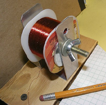
#34 wire
A wire jig comes in handy. The Butterfly/Wing nut allows adjustment of the wire tension. Hams get all tensed up when they have to wind coils. No time for a jig? Just stick a bolt in a vice and let that hold the wire spool. This ANT COIL modification is a 30 minute project and takes longer to explain it than to do it.
![]()
Clear
fingernail polish is a great tool. Visit the dollar store. The additional
winding does not have to be perfect. Just wind the wire and try not to
have too many overlaps on the turns. Coil winding at the frequency of
3.8 Mc is not critical for antenna tuning circuits. Wind more turns than
necessary and apply fingernail polish. Then trim turns as required. The
fingernail polish will hold the turns while you remove turns.
Winding the Coil- Turns information below.
1. First take your new spool of wire and unroll one end and connect it to the top of the existing coil winding on the coil form. This connection will be on the outside of the form and will at the top of the original winding.
2. Hold the coil in one hand and slowly wind the wire around the coil in the same direction as the original wiring.
3.OR stretch out several feet of wire and secure the wire reel. With a slight tension on the wire hold the coil form in both hands and slowly roll the form in the direction of the wire spool keeping a slight tension as you roll the form.
4. Wind more turns than you think will be necessary. Its easier to take remove turns then to put turns on.
5. Once the winding is finished hold the winding in place with one hand and apply clear fingernail polish to the new winding and hold the new winding in place for a minute or so. The polish will dry fairly quickly which will allow you to carefully lay the coil aside and allow it to continue drying for an additional 20 minutes and yes the polish is not "Coil Dope" and may affect the Q of the coil slightly. The use of clear polish to hold the additional winding in place will help when removing turns as you trim for resonance.
6. Do not glue the coil cover back on until full testing as been accomplished.
 3.885 Coil measures 83.5uH
Most collectors
want to put their radios on 3.885. Antenna Coil C-360 is sought after
but is fairly rare. The inductance of this original coil is 83-84uH. When
modifying coils from other frequency ranges use 83.5 as the target inductance
when adding turns. The value is not critical and usually plus or minus
5 uH will suffice.
The lower frequency coils such as those in the
4 Mc range will require less turns for the additional winding to arrive
in the 84uH range.
Typical
Coils that have been modified.
Start
by winding more turns than necessary and then turns are removed to arrive
at the correct inductance.
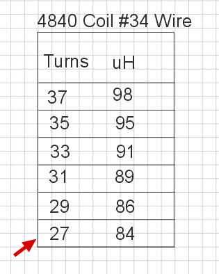
A
total of 27 turns was wired in series with the original winding to increase
the inductance to 84uH and be usable in the 3800 to 4000 range. Initially
wind more turns than estimated and remove turns as needed during
your bench check. Note in the above chart the amount of inductance that
is removed vs. turns. For example: Removing 5 turns results in a inductance
loss of 2 to 3 uH. More info on the bench check is below.
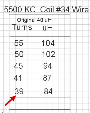
A total of 39 turns was added to the 5500 KC coil.
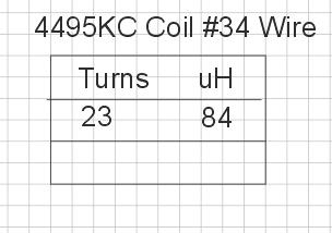
A total of 23 turns was added to the 4495KC coil. The lower frequency coils require fewer turns for 3885 KC operation.
A dip meter comes in handy but is not mandatory. Don't glue the cover on the coil until final testing has been completed. When dipping the coil be sure and extend the antenna and activate the push to talk switch to ensure that all antenna circuits are complete.
Grid
Dipping Results: In general the 3885 84uH coil will indicate a dip in
the lower 3.6 to 3.9 Mc range. (Antenna extended - PTT activated) With
the antenna retracted (PTT activated) the range was 3.9 to 4.2. Yes, I
checked my frequency with a nearby receiver while dipping.
Grid dipping an unmodified coil that has the cover installed may be accomplished using link coupling.
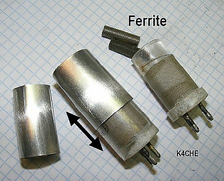
When testing
coils you can try fabricating a round aluminum shield to reduce inductance.
Ferrite can be added to the coil to increase inductance.
Test Results: Using a 4080 KC coil the shield decreased the inductance by 10uH. Inserting one of the pieces of ferrite increased the inductance by 15 uH.
![]() Cover the outside of the shield with Con-Tact paper for insulation to
prevent contacting the radio wiring during the test.
Cover the outside of the shield with Con-Tact paper for insulation to
prevent contacting the radio wiring during the test.
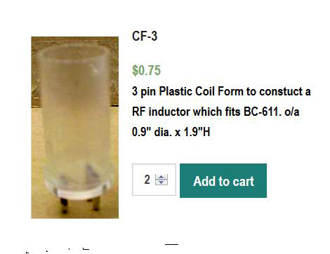
 Fair
Radio stocks the coil forms for the BC-611 and the BC-745 (Pogo Stick)
Fair
Radio stocks the coil forms for the BC-611 and the BC-745 (Pogo Stick) 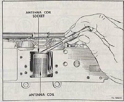
Its
easier to extract the coil by using a small screwdriver. The coil socket
is fragile.The socket has 3 pins but only 2 are used. Sometimes when extracting
the coil the "unused" pin comes out of the socket.
Final
Amplifier
Bench Testing Loading and
Tuning
Capacitance
between ANT ROD and Case.
The plug in ANT COIL L1 is part of the output
tuning for the final R-F amplifier. The output tuning circuit is a Pi-Network
and utilizes the small amount of capacitance created between the antenna
rod and the case as the "Loading Capacitor".
You
can not fully "bench test" the RF section of the BC-611 without
providing this Loading Capacitance between the ANT ROD and the radio chassis.
Assuming that you do not have the Test Case CS-81E.
Why Bench testing? It is needed in order to test the tube, the circuits, trouble shoot, check ANT COIL for resonance and determine if full output is available. Also it fun to play around with the output circuits.
Loading the final amplifier: There are numerous bench techniques that
you can utilize without inserting your radio into the outer radio
case. The simple Field Strength meter can be used to check resonance.
 And
if you have modified a higher frequency ANT COIL for use on 75 meters
- - - a bench test (out of the case) can be conducted to determine if
your modified coil will function properly in the desired frequency range.
And
if you have modified a higher frequency ANT COIL for use on 75 meters
- - - a bench test (out of the case) can be conducted to determine if
your modified coil will function properly in the desired frequency range.
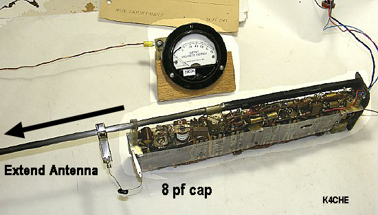
You can provide loading capacitance on your bench radio for testing by:
1. Clipping on a small value of capacitance between the antenna rod and the chassis.
2. Use a "Test Case" constructed of aluminum to house the radio and insert the radio in the "Test Case." More info below.
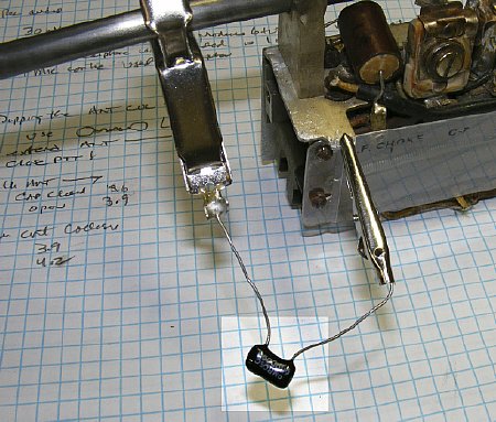
A 8pF +/- capacitor replaces the case capacitance. Extend the antenna and the radio final RF output should load for bench testing. Should work even if the antenna is only partially extended.
As an experiment a variable trimmer can be used to simulate different output loading capacitor conditions.
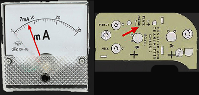
Measuring the current
at the Plate Meter Jack. The target load when the circuit is "dipped"
is 7 mA with the antenna extended. (TM 11-4019 states 7 1/2 mA) The dip
should be sharp and cover the range of 3 or 4 mA.
Simple
Field Strength Meter positioned next to the BC-611 Antenna.
A quick and easy way to check
resonance and plate tuning on the bench just place the "Simple"
FS meter close to the antenna and peak while watching the meter.
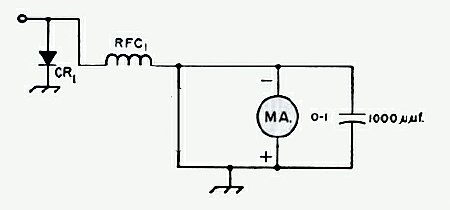
"Simple
Field Strength Meter" ARRL Handbook schematic.
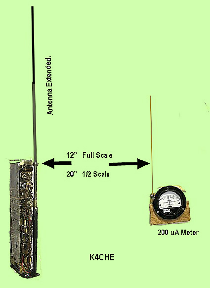
Typical "Simple Field Strength" reading vs. distance.
Conditions: Radio antenna fully extended. 8pf capacitor load. Transmitter peaked for max field strength. Field strength meter uses a 1N34 diode without any tuned antenna circuit. 12 inch antenna. 200ua meter
It may be necessary on some individual radios to use a higher frequency
coil of less inductance in order to tune the set to 3885KC. This is with
the antenna extended. This is due to age of the components and individual
radio mechanical construction. So if you have a coil on the next channel
up from 3885 try to tune the set with the higher frequency coil.
Check the plates of C12 while bench tuning - at resonance the plates should be partially meshed and not fully open or closed. Fully open indicates less inductance is needed on the ANT COIL.
ARRL
Handbook Schematic
CR1
1N34 diode or try any diode
RFC1
2.5 mH choke or anything close.
MA
Meter in the uA range for best sensitivity.
Antenna
12 inches of stiff #14 wire.
![]() Build one simple meter circuit. Use
the same 12 inch antenna and meter on all bench tests. Use this meter
as a standard on all your low power projects such as DAV, BC-611, BC-745
etc. Keep notes of the distance and meter reading of each set.
Build one simple meter circuit. Use
the same 12 inch antenna and meter on all bench tests. Use this meter
as a standard on all your low power projects such as DAV, BC-611, BC-745
etc. Keep notes of the distance and meter reading of each set.
 K4CHE
K4CHE
The TEST CASE CS-81 is fairly rare. A
"Test Case" for tuning can be fabricated.
Some
BC-611 cases have had alignment holes drilled in the top of the case by
previous owners. However if you have a unmolested case then fabricating
a Test Case might be a solution for alignment and you can preserve the
original case.
A simple
A
The simple
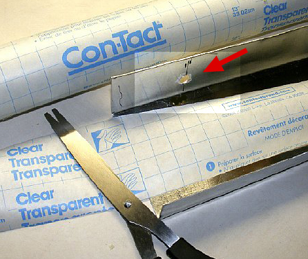
"Con-Tact paper was applied to the interior of the Test Case Enclosure for insulation. The access hole (arrow) is for tuning the capacitor C12 with a small screw driver.
A simple
Revised
Test Case Chassis with Top End Cap and side door.
Tests
were conducted on the original ![]() shape chassis without a top end cap and side door. RF Tuning was easily
accomplished and the radio was removed from the Test Case and inserted
into a BC-611 case. However It was determined that the Final RF tuning
was considerably off resonance and RF output reduced - a side door and
top cap were than added to the enclosure and the results improved. However
receiver tuning with the original
shape chassis without a top end cap and side door. RF Tuning was easily
accomplished and the radio was removed from the Test Case and inserted
into a BC-611 case. However It was determined that the Final RF tuning
was considerably off resonance and RF output reduced - a side door and
top cap were than added to the enclosure and the results improved. However
receiver tuning with the original ![]() chassis was satisfactory.
chassis was satisfactory.
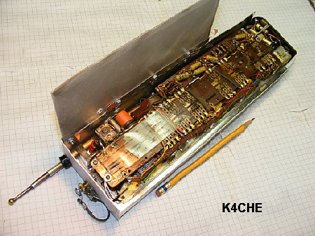
Test
Case Enclosure
The
top end cap and side door added enough coupling to closely simulate the
actual radio case. A side door was fitted with a scrap piece of piano
hinge material. Holes were drilled for tuning access.
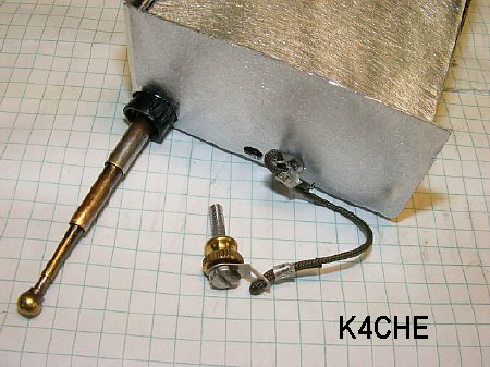
A
plastic grommet insulates the antenna. A "hold down" bolt was
added to hold the radio in position and to provide an efficient ground
connection between the radio chassis and the Test Case enclosure.
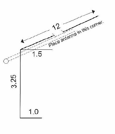
The hinged door on
the test case comes in handy when inserting the top hold down bolt. A
simple card board spacer is used at the bottom to ensure a closes fit
between the base of the extended antenna rod and the top corner of the
test chassis. Don't forget Con-tact paper for insulation on the inside
including the door.
Improvise-Adapt-Overcome
The Side Door
does not cover the entire length of the chassis in order to leave the
TR switch exposed. My side door length was determined by the piece of
scrap aluminum I had in the junk box. ![]() But leave the Push
To Talk tab exposed for testing.
But leave the Push
To Talk tab exposed for testing.
Tuning
Q.
Why not just determine an accurate fixed "loading" capacitance
and use that instead of a "Test Chassis"
A.
Tried to do just that. The Test Chassis or the actual BC-611 case presents
a complex impedance to the RF output of the BC-611. So I put those calculations
in the "Too Hard To Do Box".
Q. Which is best when tuning the transmitter using plate current or a
peak in Field Strength?
A. It helps to determine proper loading with a plate current reading but in a pinch just using the Field Strength will suffice. If possible use both - - - the plate current dip and peak of Field Strength on the simple Field Strength meter should agree.
Q. Won't the metal objects in the shop interfere with the Field Strength meter?
A. Just extend the BC-611 antenna and try and and keep it clear.
Q.
Will I be able to see the effect of modulation on the Field Strength Meter?
A.
Yes.
Q.
What about RF Exposure?
A.
Using the ARRL calculator the tests on the bench seem to be within compliance.
I'veway eenbay orkingway etc.
Q.
My thumb hurts from holding the PTT switch in the transmit position.
A.
You can jam something in the spring area to hold the set in transmit but
be careful the switch is fragile. You can also remove the spring.
Q. How much RF output power will the BC-611 transmit?
A. The transmitter specs are 360 mW. You can calculate the input power - plate current X voltage. Figure 50 percent efficiency for RF output.
Q.
How can I check the actual RF power output?
A. Use a #47 or 49 bulb - see below for details.
Q. I hooked up a #47 bulb between the antenna and chassis and it doesn't light.
A. You have to match the bulb with a simple network. See below for details.
Q. If I use the home brew aluminum "Test Chassis" for final tuning what happens when I actually insert the radio into its case. Will it stay tuned?
A.
The final RF tuning as well as receiver alignment will be very close.
Close enough too provide sufficient RF output for use at the next military
meet or hamfest.
The excuse of not having a CS-81 case to tune your set is weak. Any procedure
is better than leaving the set on the shelf. Use some scrap aluminum and
fabricate your own Test Case.
Q. Will my hand on the case effect tuning.
A. Yes, a small amount. Its best to tune the set with one hand on the chassis.
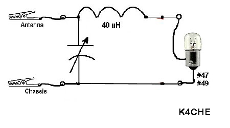
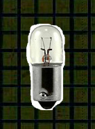
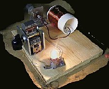
A simple "L" network will match the BC-611 output to a #47 or #49 bulb. An interesting experiment and will actually confirm the RF output with a "visual" indication. When the bulb lights up it makes you feel like you are doing some real radioing.
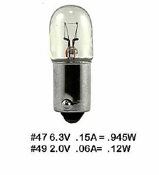
#47 bulb at half brilliance is an indication of approximately 1/2 watt.
Bench
test your bulbs at full rated voltage and then vary the voltage to determine
the amount of brightness this helps in estimating the RF output of the
set.
The #49 bulb at full voltage does not glow as bright as the #47 bulb at full voltage as it is a much lower wattage. BTW an ole bench trick is to put the #49 in series with unknown crystal oscillator circuit to limit current this might save those new miniature crystals.
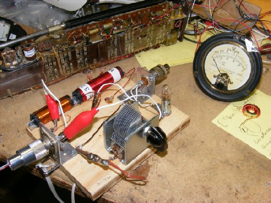
My
bench test tuner can be configured in many ways for different tuning situations
using alligator clips.
BC-611
load test L network consisting of a capacitor and a coil.
Procedure: Collapse antenna rod. Adjust C12 on the radio to 1/2. Watch F.S. meter and plate current. Adjust L network capacitor for a dip on plate current and look for a peak on the F.S. Meter.
![]() You
can try using one of your spare higher frequency ANT COIL's as a temporary
substitute for the 40uH coil in your L network.
Play with it.
You
can try using one of your spare higher frequency ANT COIL's as a temporary
substitute for the 40uH coil in your L network.
Play with it.
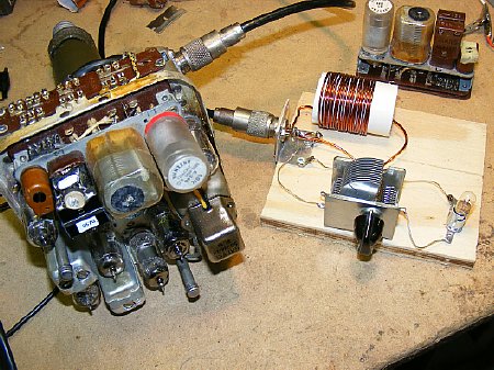
The L network bulb load is used on a lot of low power projects to provide a indication of power out. Shown above it is being used on the BC-745 Pogo Stick.
An alternate Bulb Loading procedure for bench testing on 3885 KC is to take a high frequency ANT COIL such as 5500-5775 KC and remove turns to arrive at a target inductance of around 20-25 uH. Use this coil in the radio for 3885 Bench Tune up for light bulb loading. Remove about half the turns on a 5500 KC coil. "That's about all I know about loading bulbs."
Pogo
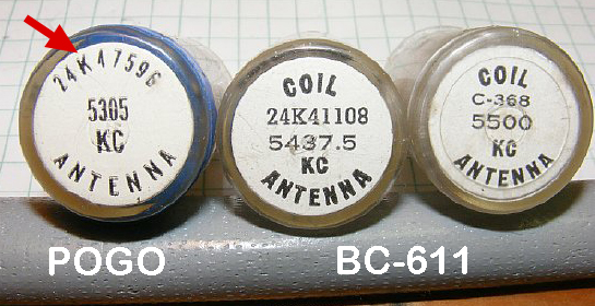
Stick and BC-611 ANT coils.
The Pogo Stick
coil (far left) can be identified as the part number is printed in a circle
around the outer edge of the coil instead of in the center.
Note that the BC-611 coil in
the center also has a 24K part number but this is a Manufacture part number.
The Pogo stick coil frequency range inductance is different than the BC-611
coils. For instance in the above example the Pogo stick coil on 5300 Kc
will have a drastic difference in inductance than the center coil even
though it is the same frequency range. The Pogo coil will have a inductance
that will be 10-15 uH lower. On the lower frequencies the inductance can
be up to 20-30 uH difference. The Pogo coils will always have less inductance
for a given frequency range.
Pogo Stick Coils
Q. I have a Pogo Stick coil marked 3865 KC with a outer rim part number 24K49752. Can I use this in the BC-611 on 3885 KC as there is only 20 KC difference. Can I just plug it in?
A. No, the inductance of the Pogo 3865 coil will be insufficient. The coil is rare - save it for a actual BC-745 Pogo project.
Additonal Coil Information by Robert Downs.
I have many of all of the BC-611 antenna and tank coils, including the Free Worlds supply of the antenna coil that covers 3885 KC, so have never had any impetus to find out but as the Pogo-Stick goes down to a lower frequency than does the BC-611, there may be a Pogo-Stick antenna coil that will tune a BC-611 antenna to 3885 KC. But I dont know that for a fact.
On the general subject of the BC-611 antenna and tank coils, they will be found marked two different ways. The early ones are all marked with a single frequency and with Galvin part numbers. The later ones are marked with a frequency range and with the Signal Corps model number. But both groups are the same, meaning that as an example, the range-marked coils that cover 3885 KC are marked C-360 (3825-4025 KC) for the antenna coil and C-371 (3825-4225 KC) for the tank coil. (and note that in this case C = Coil, not Capacitor). An antenna coil marked 3885 KC is the same coil as a C-360 and a tank coil marked 3885 KC is the same coil as a C-371.
One coil related problem that I have encountered twice was where the C-371 tank coil worked OK but in order to get the antenna to tune up on 3885 KC, I had to substitute a C-361 antenna coil. Both radios had a very heavy or thick coating of MFP varnish to the extent that the top end of the chassis was brown instead of amber.
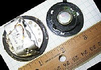
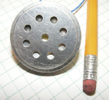
Microphone Substitution
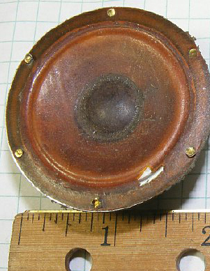
The original microphone element (exception A models) is basically just a small "speaker" feeding a step up transformer. Provided that the transformer is OK you can replace a bad "speaker" element with a small 16 to 30 ohm speaker. Try different speakers and determine which sounds best.
![]()
BC-611's used
a step up transformer in the microphone circuit with the exception of
the early "A" model. When experiencing failure of the microphone
circuit check the transformer as it may be OK. A good transformer can
be used with a substitute element.
Don't throw the transformer away.
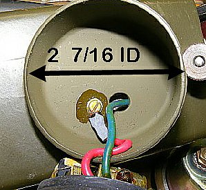
The ID of the microphone housing is 2 and 7/16 inches depending on manufacturer.
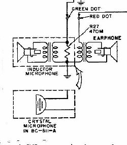
Early "A" model radios utilized a crystal element without a transformer. Later BC-611 models used a "Inductor" speaker type of microphone with a transformer.
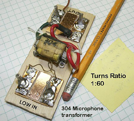
Microphone transformer test jig.
Later model BC-611's transmitter microphones incorporated a low to high transformer.
When experiencing failure of the microphone circuit check the transformer as it is usually good. The above test jig was utilized to test different microphone elements as a possible replacement.

The early models B,C,D,and E microphone assemblies have a 470K (SR27) resistor across the secondary. The later F models did not. TM-11-4019 describes this resistor as a "load resistor".
![]()
Plenty of audio transformers on ePay. Look for high to low impedance.
Green
wire test no load conditions.
![]() When testing at normal voice levels the voltage output of a microphone
assembly should be around 1 volt Peak to Peak on your scope. This is a
"no load" voltage with the microphone lead disconnected from
the radio. The resistance of the green lead to chassis ground should be
approximately 2.5K (Two point five K) again when it is not connected to
the radio. When testing with an analog type meter on the low ranges you
should be able to hear a faint click in the microphone.
When testing at normal voice levels the voltage output of a microphone
assembly should be around 1 volt Peak to Peak on your scope. This is a
"no load" voltage with the microphone lead disconnected from
the radio. The resistance of the green lead to chassis ground should be
approximately 2.5K (Two point five K) again when it is not connected to
the radio. When testing with an analog type meter on the low ranges you
should be able to hear a faint click in the microphone.
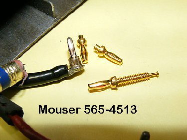
Miniature banana plug: Mouser part 565-4513 and 4513#
Crystal
Element - No transformer needed.
A crystal microphone element can be used with
the BC-611 and does not need a transformer. Output from the element should
be several volts PP under no load conditions.
![]() Older CB microphone
usually contained crystal elements. Try several different elements for
best audio sound.
Older CB microphone
usually contained crystal elements. Try several different elements for
best audio sound.
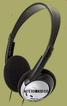
Old headsets earpieces are a good source of substitute "Inductor" microphone elements. Usually around 30 ohms.
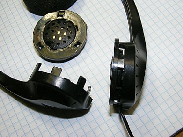
The older sets were easy to disassemble. Typical earphone is 30 ohms. Look in your closet for that old Walk Man headset.
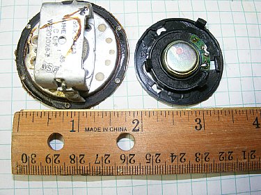
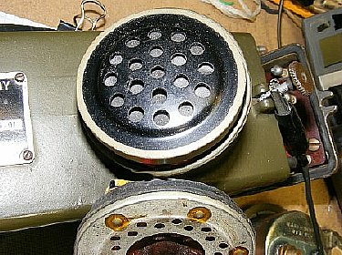
Original
microphone on the left. Replacement on the right.
The earphone fits easily into the microphone compartment.
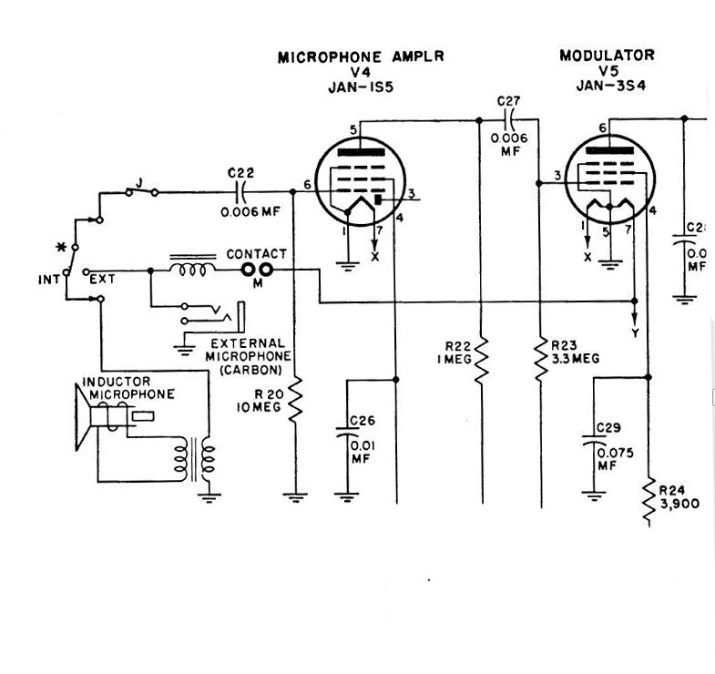
"F"
model microphone circuit.
Late model BC-611's
had provisions for an external carbon microphone.
As
a last resort on sets that are missing the speaker type "Inductor"
Microphone or have a bad transformer you can always sub a carbon button
as a replacement. Later F model radios with a special bottom door assembly
had provisions for a carbon microphone to be plugged into the bottom of
the set. The carbon button will require rewiring 1.5 volts and a choke/resistor
in series. A transformer is not needed.
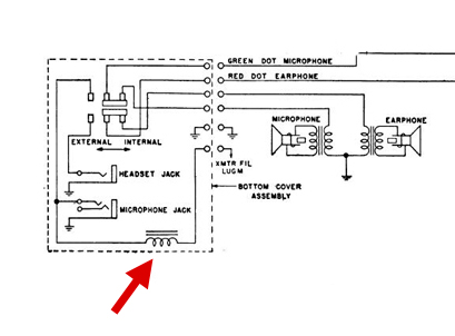
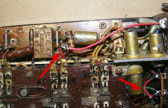
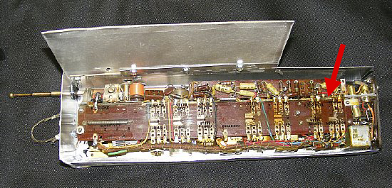
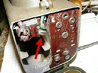
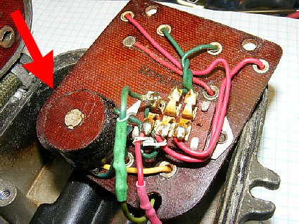
The F model with the bottom door assembly contained a choke that was in series with the carbon microphone. Bench measurement of the choke was 16 ohms / 8mH
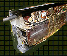
"F" model bottom door assembly circuit and switch board.
The late "F" model uses a 8mH choke (Red Arrow) with a resistance of 16 ohms in series with the carbon mic. This is needed in the carbon mic circuit to develop voltage.
A telephone button will fit.
Depending on the button manufacturer you may have to remove the outer
rim for additional clearance. Dremel tool, razor saw, file, long nose
pliers,wire cutters,small screw driver, grinder,
When using
a carbon microphone as a substitute you will have to supply 1.5 volts
as well as a small choke. An additional wire carrying 1.5 volts will have
to be provided to the microphone compartment. Try
running a 1.5V wire from inside the chassis through the bottom phenolic
terminal board.
Battery
or Inverter Power?
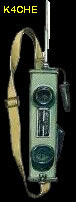
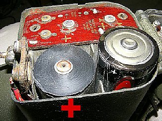
k4che battery tray and
a early model "Italian" inverter.
A simple k4che battery tray can be
constructed from aluminum and uses wood with a copper strip for the ends.
"Dollar Store" batteries work fine and will sustain
ops for a couple of meets.
More info on the
inverter is below.
My Home Brew inverter compared with a more compact Italian inverter.
A simple battery box. Link below.
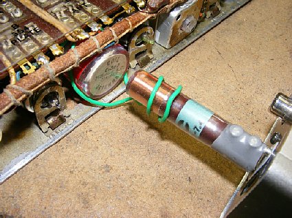
I prefer to fuse all my power supply projects. Enclose the fuse in a piece of clear spaghetti tubing.
Wiring
for a battery tray can be made simpler by using a "Dual" snap
on connector. Be sure and insulate the terminals. The "Dual"connector
is available at All Electronics item # BH-29. Keystone also manufactures
a Dual connector and is available from Mouser and Digi-key.
Special thanks to
Chuck WD8AXA for this info.
More details
of the battery box can be found at:
http://k4che.com/BC-611-20Box.htm
A tray made by Craig N3TPM uses battery holders. Very neat construction.
Very neat construction by N3TPM. Rivits were used for hold down fasteners.
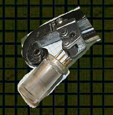
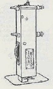
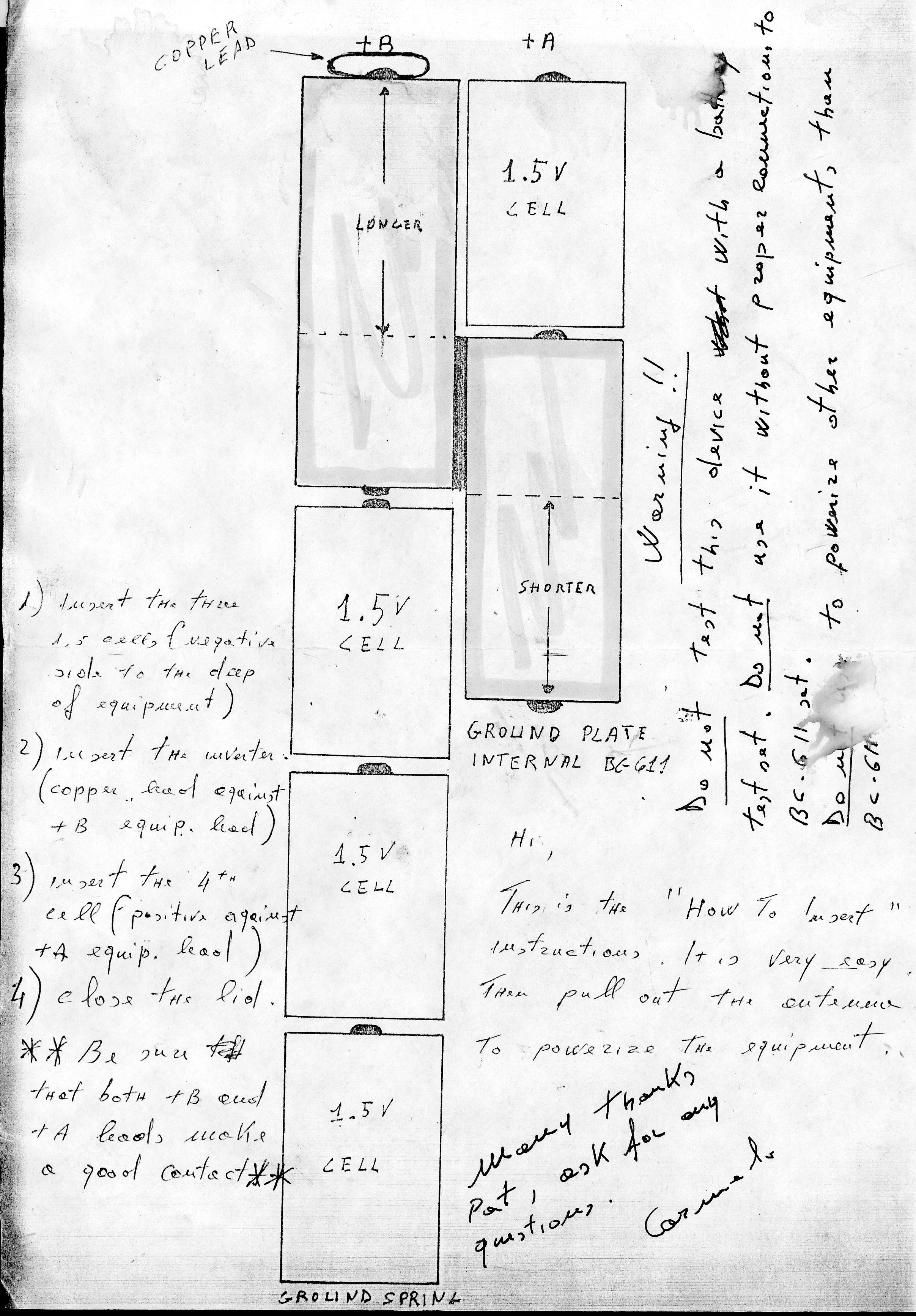
An early model of the "Italian" inverter. Note the battery contacts which were sometime intermittent. The spring type connector often had to be adjusted.
CLICK
to enlarge
An "Early" Italian instruction sheet. I do not have a later sheet.
Later
model with spring contacts.
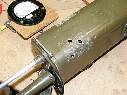
BC-611
typical Italian Inverter Bench test voltages and currents:
Transmit 110V and draws .510 Amps.
Receiver 95V @ .250Amps
Inverter Quick Check
Quick
Check: Close the bottom door and power up the radio by pulling out the
antenna.
Turn radio upside down and open door to expose the +
terminal of the inverter. (Round brass button). Measure between
the + terminal and chassis ground. The voltmeter
should indicate around 100 volts DC. This voltage may remain
for hours as the internal capicators discharge.

Q. Can I hear the inverter whine by listening with my ear to the outer
case of the radio.
A.
No
Q.
How long does it take for the high voltage to bleed down to a safe level.
A.
Hours
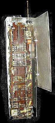
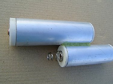
The
Italian inverters develop high voltage. When removing the inverter from
the radio be careful - do not come in contact with the +
end. After removal discharge the red end shown below because bleeder
resistors have either not been installed or they or of very high value and
take a long period to discharge. Discharge with a 1K resistor, do not discharge
with a direct short between Plus end and battery end.The smaller tube is nothing but a empty shell that provides contact with the radio case plunger and the bottom of the 1.5 volt filament battery.
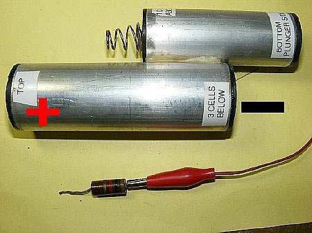
Discharge
the inverter (RED end) after carefully removing from radio.
Use a low value resistor
in series with the shorting wire. Do not short our the terminals with
a direct wire.
TM-11-4019 Repair Manual is useful on the bench.
Robert
Downs WA5CAB has excellent reprints of manuals.
http://www.vendio.com/stores/wa5cab/
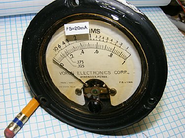
An old 1 ma meter was found and a shunt was added to turn it into a 20 mA meter. A 15 or 20 mA meter makes it a lot easier to see the resonance dip during tuning or to just detect that "slight dip" when getting close to resonance.
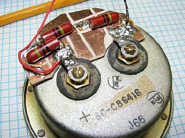
Solder lugs on the meter terminals hold a piece of copper clad "PC" board that was etched with a Dremel tool.
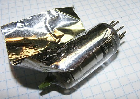
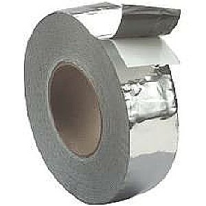
Lost tube
shield? Use aluminum duct tape.
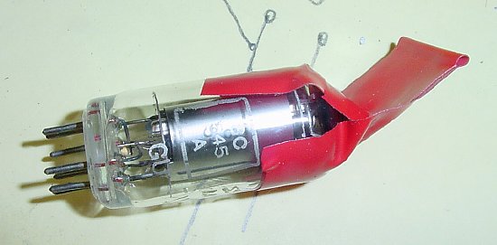
When checking tubes plastic electrical tape helps with insertion and extraction. Red works best.
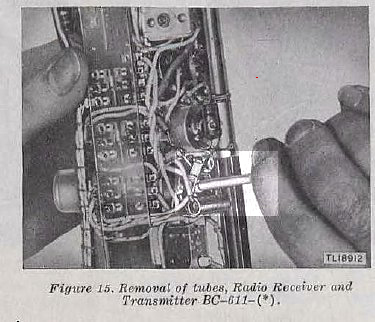
TM 11-4019 Figure 15
Some times you can assist removal of a tube using a wooden dowel.
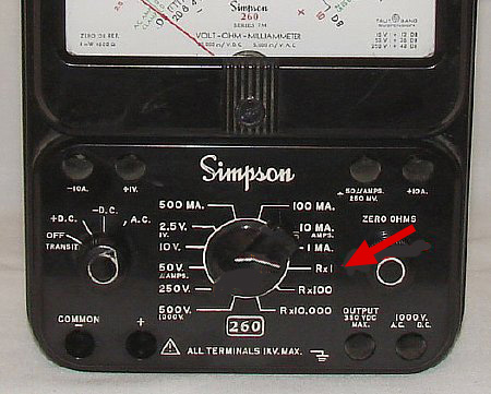
![]() When
checking tube filaments be sure your analog meter is only utilizing 1.5
volts as the internal battery during a resistance check using the lower
ranges. Most "Analog" meters use a higher voltage when the
high resistance ranges are selected and the higher voltage will burn out
the 1.5 volt filament on the tube you are testing.
When
checking tube filaments be sure your analog meter is only utilizing 1.5
volts as the internal battery during a resistance check using the lower
ranges. Most "Analog" meters use a higher voltage when the
high resistance ranges are selected and the higher voltage will burn out
the 1.5 volt filament on the tube you are testing.
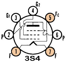
All tube filaments in the BC-611 should measure approximately 8-9 ohms between pins 1 and 7. However the 3S4 has two filaments using pin 5 as a center tap. So between pins 1 and 7 you should measure approximately 17 ohms. Between pins 1 and 5 and 7 and 5 approximately 8 ohms. Read the Caution in the previous paragraph.
CLICK
to enlarge
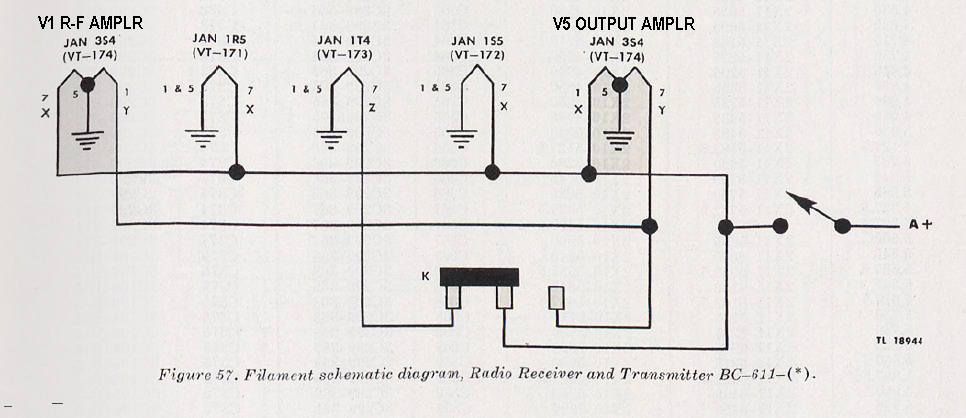
Figure 57 BC-611 Filament Schematic
![]()
A Dremel tool can be used
to enlarge the interior of the FT 243.
There are several sources of crystals and most of them are in miniature holders which can be inserted into the standard FT 243 holder.
The internal
crystal blanks inside the miniature holders are very small as compared
to the original FT-243 crystal blanks. However in the BC-611 oscillator
circuit there is minimal heating due to a very low current draw - - -
I have not experienced any failures of miniature crystals in the BC-611.
Home
brew switch cover
![]() Be sure and install the plastic switch cover. The cover protects you from
High Voltage and protects the fragile switch contacts and components when
inserting the radio back into the radio case. A new cover can be cut from
thin clear package material or a replica cover can be ordered from WA5CAB.
The WA5CAB cover can be ordered for early or late model radios and has
the switch terminal information printed on it just like the original.
Be sure and install the plastic switch cover. The cover protects you from
High Voltage and protects the fragile switch contacts and components when
inserting the radio back into the radio case. A new cover can be cut from
thin clear package material or a replica cover can be ordered from WA5CAB.
The WA5CAB cover can be ordered for early or late model radios and has
the switch terminal information printed on it just like the original.