T-17 Carbon Telephone Transmitter Button Mod and a Hodge Podge of T-17 Info.

The
T-17 an old friend..
Index Click to Navigate
Telephone
Button Modification
Specifications
and Manufacturing Data
Capacitor
Info
Bench
Checks
Rewiring
and Switch Info.
Holes
Hooks
Alternate
Uses for the T-17

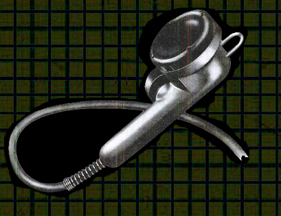
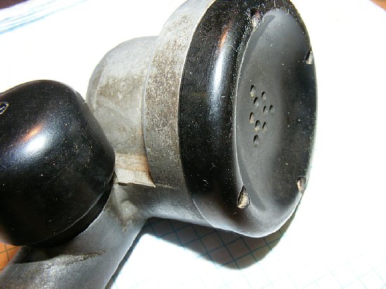
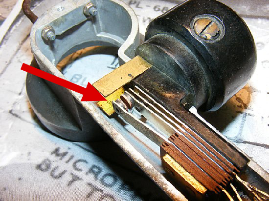
By removing the outer rim most standard telephone transmitter buttons can be modified to fit the T-17 housing. Much better than just attaching the button to the holder with black tape as shown below. Details on rim removal below.
The
standard telephone button transmitter does not fit "inside"
the T-17 housing. Shown above is a typical ham mod using black tape to
attach the button to the T-17 case.
Cutting
the outer rim on the telephone button to resize the transmitter button
for proper fit will be a much better mod than just using tape to fasten
the button to the front of the T-17 housing.
Go first class with a 30 minute project.
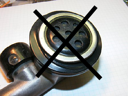
Here is another ham mod using the telephone transmitter. Nice paint job.
There is a better way. Details below.

Thousands of T-17's were manufactured during and after WWII.

CLICK
to enlarge TM11-487I
T-17-(*)
Specifications.
T-17 Type/Manufacturer Location List
A listing of T-17 microphones that have passed through the hands of Mr. Robert Downs. Robert points out that this list below is just a partial listing of T-17s that were manufactured and that others probably exist especially earlier models.
ALA
= Aluminum Body w/clear anodize finish.
ALB = Aluminum Body painted black wrinkle
BKP = Black Plastic Body probably Shure style with solid handle and screw-in
strain reliT-17-D
T-17 751-CHI-41 ALA BLACK
SW-109
T-17
753-CHI-41
ALA
T-17
753-CHI-41
BKW PAINTED BLACK
WRINKLE ASSUME ALUMINUM BODY MAY BE DEPOT
T-17
1050-WF-42
ALA
T-17 1496-PHILA-42 ALA
T-17
1545-PHILA-42 ALB
BLACK
SW-109 NOT CLEAR WHETHER "B" REFERS TO SWITCH KNOB OR BODY BUT PROBABLY
SWITCH
T-17 XXXX-PHILA-42 ALA
BLACK SW-109
T-17
6271-CHI-42 ALG
PAINTED GREY
T-17
13751-PHILA-43 BKP
BLACK SW-109 BLACK PLASTIC
T-17 13752-PHILA-43
ALA BLACK SW-109
T-17 13755-PHILA-43 ALA
T-17-A APPARENTLY SKIPPED, WHICH IS NOT UNUSUAL. NOMENCLATURE SOMETIMES
ASSIGNED THEN ORDER CANCELLED
T-17-B 23074-PHILA-43 BKP BLACK SW-109
BLACK PLASTIC SHURE
T-17-B 10172-PHILA-44 BLACK SW-109
BLACK PLASTIC SHURE
T-17-C APPARENTLY SKIPPED, WHICH IS NOT UNUSUAL. NOMENCLATURE SOMETIMES
ASSIGNED THEN ORDER CANCELLED
T-17-D 10612-PHILA-44 BLACK SW-217 GREY
PLASTIC
T-17-D 10612-PHILA-44 BLACK SW-217 GREY
PLASTIC PJ-068 MAY BE REPAIR
T-17-E 40172-PHILA-44 ALA NOTE SAYS
WRONG CORD PJ-068 CONTRACT # MAY BE TYPO
T-17-F 25076-PHILA-54 ALB
BLACK SW-109 PAINTED BLACK WRINKLE
T-17-D 79-819 BLACK
KNOB GREY PLASTIC PJ-068 SWITCH KNOB NOT MARKED
T-17-Fr none BKP
BLACK PLASTIC PL-68Fr NATO (FRENCH) CONTRACT
Additional T-17 versions submitted:
T-17
3084-CHI-42 BLACK
SW-217 Grey Plastic stamped by Univ Micro, Inglewood CA. (K4CHE Inventory)
T-17
102-DAY-44
BKP SW-109 Switch
marked "Shure SW-109" (WA4OBJ Inventory)
T-17-D 19332
PH-44 22 Greenish
Plastic Body. On the back is molded: Signal Corps T-17-D CAAG 19332-PH-44
22 with black SW-217 button bearing a Utah "U' logo in the center.008
Bypass Cap. (WB4OGM Inventory)
T-17
424-NY-40
ALA Black SW-109 with
"K" inside a circle. (VE3BBM Inventory)
T-17-E
10172-PHILA-44 ALA
Black SW-109 with "K" inside a circle. (WB4OGM) Inventory)
A good site to visit when looking for military radio items.
http://www.vendio.com/stores/wa5cab/category/robert-s-military-radios/catId=4143036
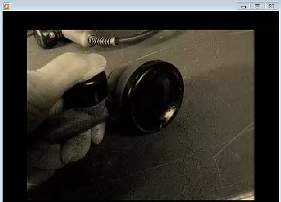
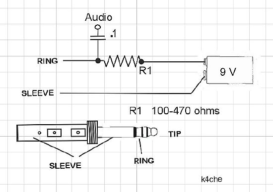
Tired of banging your T-17? Try replacing the carbon button.
Click here for video.
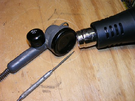
Remove the black sealant from the cover screws with a Hot Air Gun and a pick. The gun also comes in handy with heat shrink tubing and trouble shooting thermal problems in equipment and don't forget to use it on that black wrinkle paint. Harbor Freight - cheep - Don't forget your coupon.
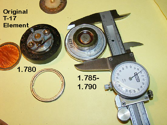
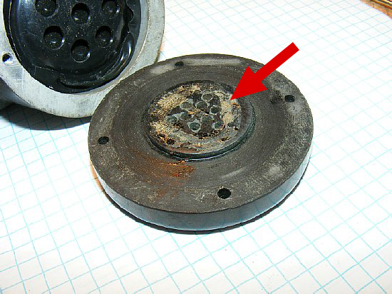
Original
T-17 carbon element on the left.
The typical unmodified telephone carbon button (AKA telephone transmitter) outer diameter is slightly larger than the original T-17 button. It don't fit. You have to remove the outer rim.
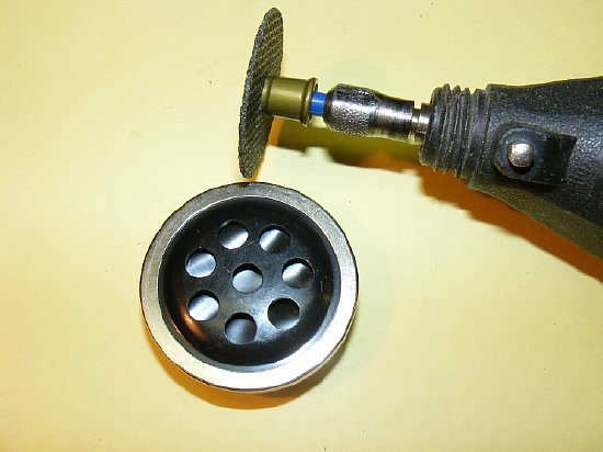
A
DREMEL tool with a cut off blade makes a neat cut through the outer rim.
Wear Safety Glasses.
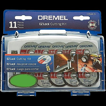
Cut off wheels for the standard Dremel tool come in handy.
Wear Safety Glasses
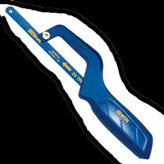
Or use a hack saw blade or a thin file - you will figure it out. It is a simple five (5) minute project.
Carefully remove the outer rim.
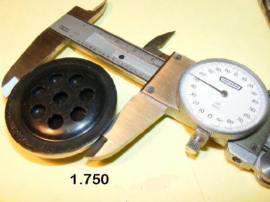
Typical
Standard Telephone Transmitter with outer rim removed.
This "modified" telephone transmitter button had a diameter of approximately 1.750 inches and will fit in the space on the T-17 housing previously occupied by the original T-17 carbon module.
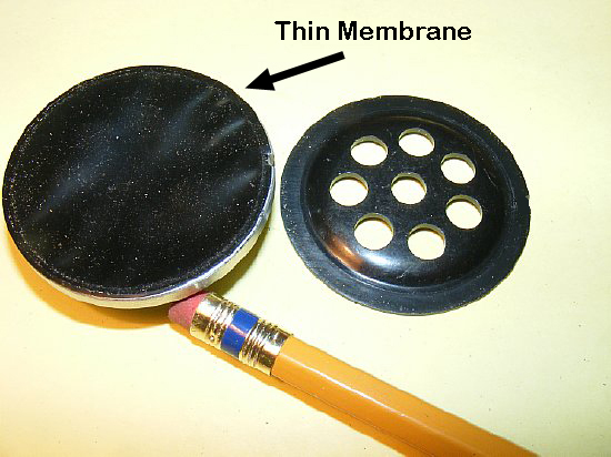
Telephone
button with outer rim removed.
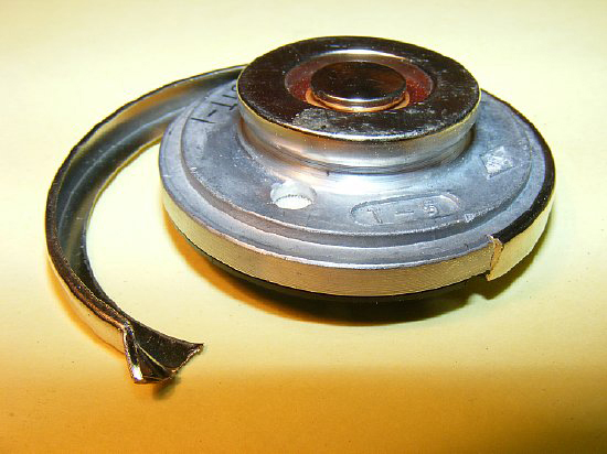
The
actual telephone button shown above has a thin membrane which is sealed.
After "carefully" cutting and removing the outer metal rim the
inner sealed element will remain intact. The "wind" blast piece
with the holes fits over the membrane assembly but can be removed - -
- but I like to use it to protect the thin membrane.
CLICK
to enlarge.
The standard capacitor value for the T-17 was .01
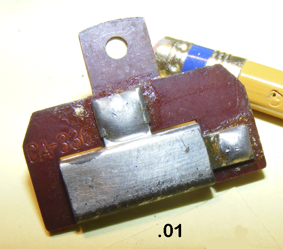
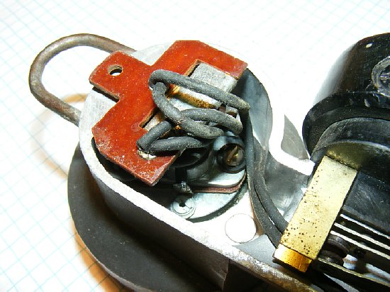
Early
.01 capacitor.
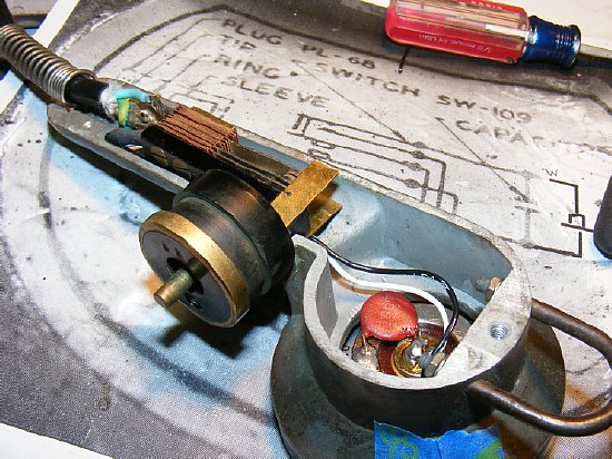
This early T-17 used a .01 audio enhancement /bypass capacitor that was wired and mounted in the housing behind the carbon element. Because of the large physical size of the capacitor it had to be wired separately. This particular example came from a T-17 with a data tag of 1494 PHILA-42

A
.01 capacitor is used and in this case soldered in place on the rear of
the telephone button. Soldering the capacitor direct to the carbon button
was a common procedure in later models and made wiring simpler.
Q. What is the purpose of the capacitor?
A. Probably meant as a bypass capacitor. Values of .01uF are commonly used in HF equipment in the 3 to 30 Mc range. The 3 conducor T-17 microphone cord was completely unshielded and could easily act as an antenna and pick up RF.
Q. Is there any loss of audio voltage with the capacitor installed?
A. No. I tried several bench tests using audio generator and acoustical coupling with different microphones with and without the capacitor. No significant different in voltage output was noticed at normal voice frequencies.
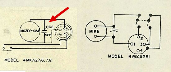
G.E.
used a .008 capacitor in their carbon microphone used in mobile
applications.
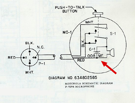
Motorola
also used a .008 audio/bypass capacitor
Q. Why did G.E. and Motorola use a .008 capacitor?
A. I don't have a clue, it would seem to be easier to use a more common value. But perhaps the capacitor was also used to enhance audio. Most early mobile commerical equipment by G.E. or Motorola operated in the 30 to 40 Mcs frequency range perhaps that is the reason for the choice of a .008
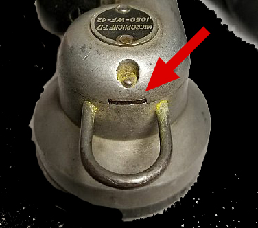
Q. Why does my T-17 have a slot in the top of the housing? I've been told its for noise cancellation.
Ans.
The slot was designed to hold the early style capacitor.
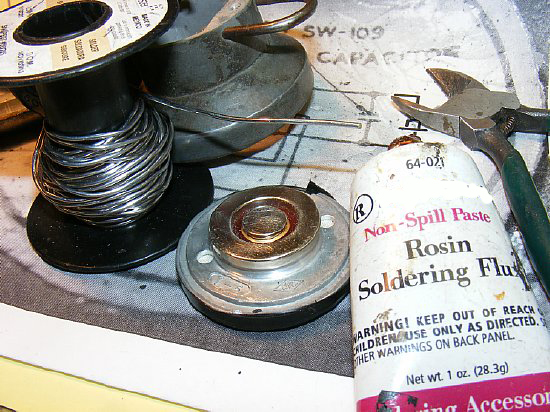
When soldering to the modified telephone button use a little rosin flux for a nice quick connection. 'Scrape and clean the area to be soldered. Don't overheat the button. A 150 watt iron comes in handy and will allow a good quick connection with minimum heating of the telephone button and its carbon granule contents.
With a new .01 capacitor there is plenty of room in the case.
Wrap a single layer of black tape around the edges which will holds the "screen" and telephone button inner assembly together and then insert into the T-17 housing.
The T-17 outer cover will easily fit.
NOTE: While you have the cover removed consider either enlarging or drilling more holes in the center. A discussion on holes is presented later on this page.
Plenty of room for the modified telephone element.
FINI
CLICK to enlarge
After the end of WWII Shure continued with the manufacture of the T-17s.
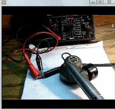
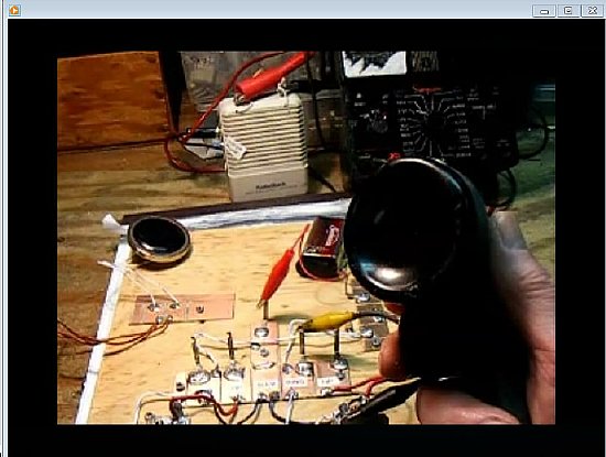
A quick check of the T-17 can be made using a resistance test.
CLICK here for Resistance Test Video.
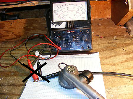
It didn't take long while testing to get tired of fooling around with clip leads.
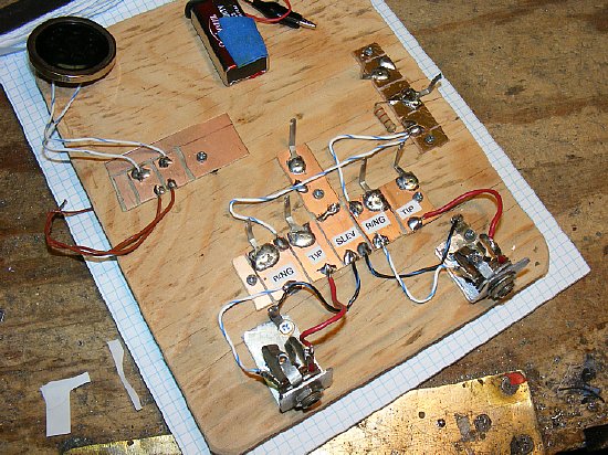
A test jig was fabricated with PL-68 jacks and easy access solder pads for the Tip, Ring, and Sleeve. In addition separate solder pads were created for testing telephone carbon buttons.
A simple DC loop to check audio response.
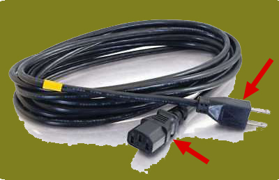
In the event you have to completely replace the cord a 3 wire computer monitor AC supply cord might be pressed into service. Don't forget to cut off the ends.
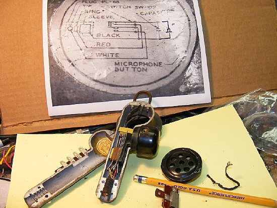
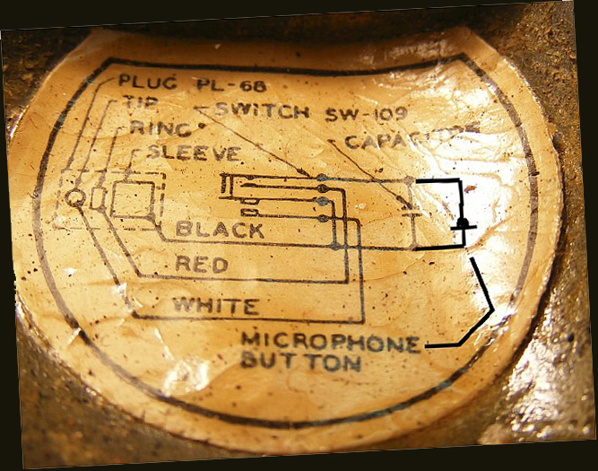
During a complete rewire a "large" schematic comes in handy.
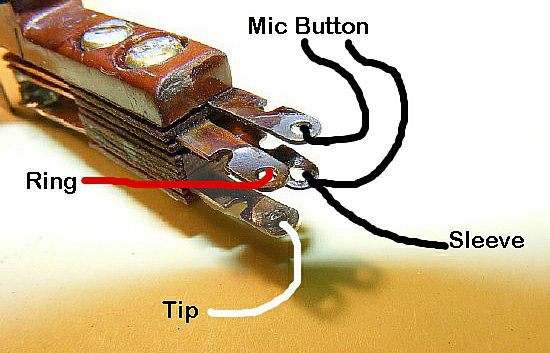
The
larger contacts are utilized for Push to Talk.
There
are two sets of leaf contacts on the Push To Talk switch. The leaf set
with the larger contact points are connected to the "Tip" and
Ground and used for keying the Push to Talk relay in the transmitter.
The other pair of contacts are utilized for the low voltage - low current
microphone element circuit.
CLICK
to enlarge.

Q. Is the T-17 microphone cord shielded?
A. No. The 5-6 foot cord was not shielded. Perhaps that is the reason for the .01 bypass capacitor. The unshielded cord could act like an antenna in a high RF environment.
A relay burnishing tool is perfect for cleaning the switch contacts.
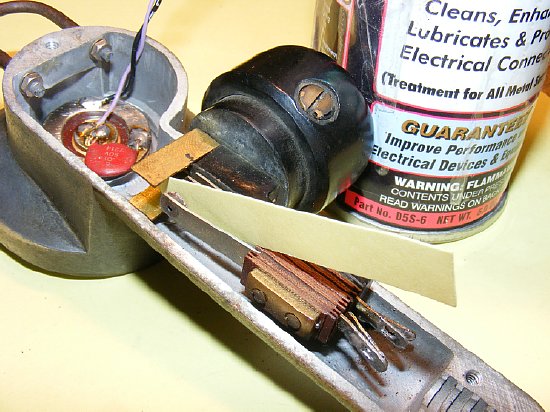
Or DEOXIT can also be used as a excellent contact cleaner. Soak a piece of thin card board and insert between the contact points - compress the switch and pull the card board back and forth between the contacts.
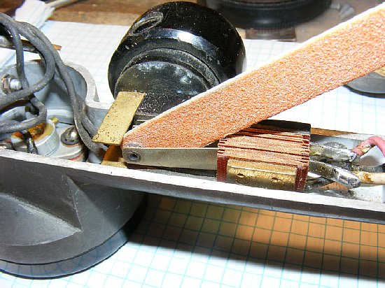
Often the special alloy on the larger Push to Talk contacts become so corroded that an aggressive approach to cleaning is necessary. Shown above is a emery board in use. Wally World cosmetic section.
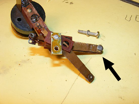
In
extreme cases of corrosion on the PTT contacts the leaf switch can be
disassembled in order to access the special alloy contacts for cleaning.
BUT
ONLY REMOVE one screw and rotate the leaf out of the stack. Don't remove
both screws - you will be sorry.
Lacking proper crimp terminals the substitute cord wires can be soldered to the PL-68 terminals. Works good and lasts a long time. It's not a rocket ship - just a hobby project.
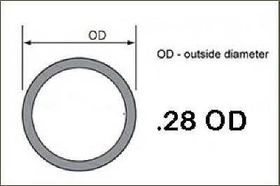
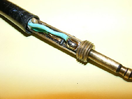
A typical OD of a original T-17 cord was .28 inches. The standard uncut length of the cord was 6 feet.
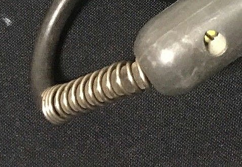
When selecting a replacement cord remember that a outer diameter of the replacement cord must be chosen that can be inserted through the strain relief spring. You will have fun with this.
Fair
radio has "cutoff" cords with a PL-68 attached.
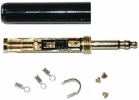
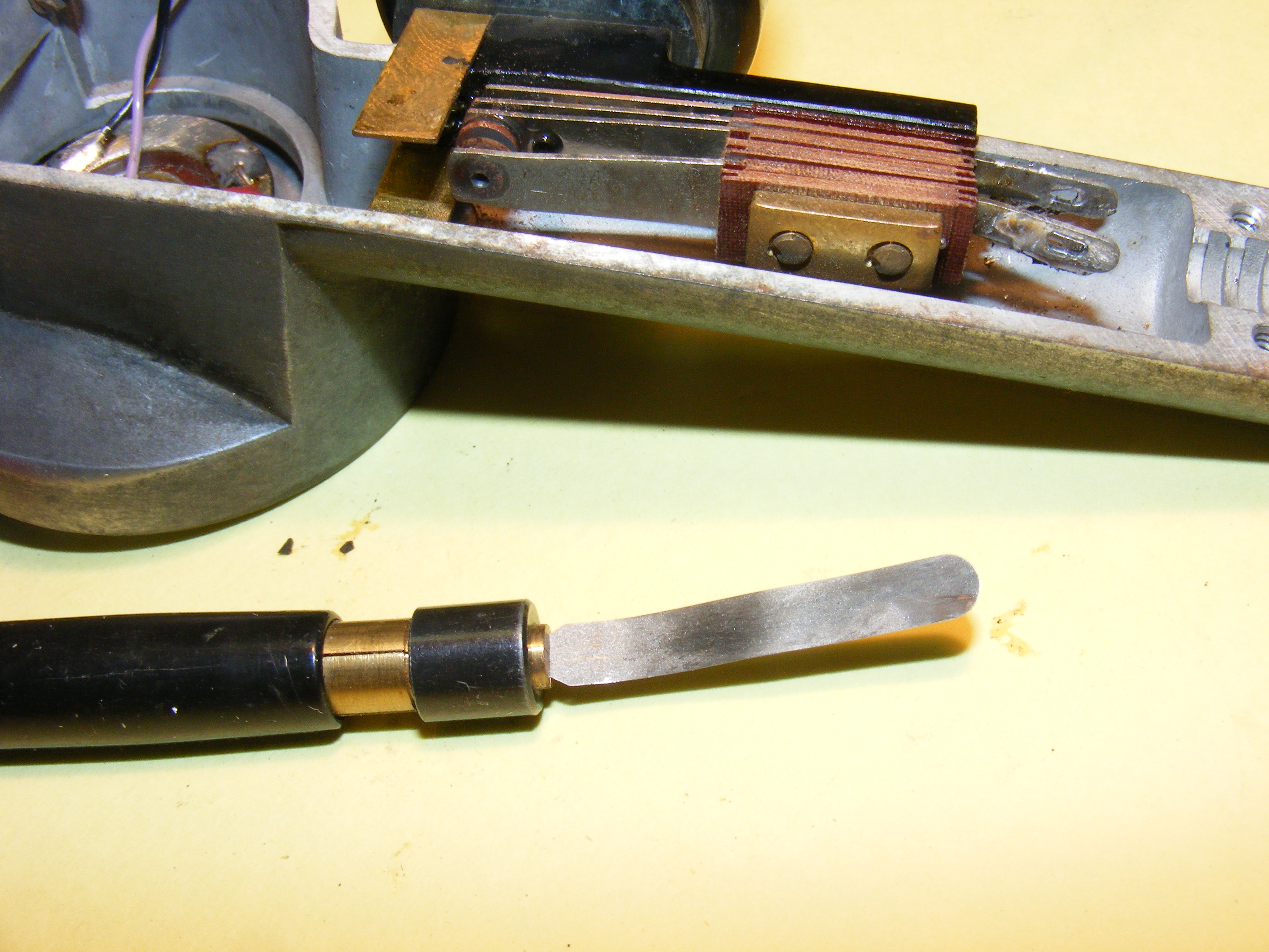
What to do with those little screws?

CLICK
to enlarge. KC4TOS
photo.
Mike Hanz comments: "Attached is a photo of the screwdriver. It's still made by Neuses Tools in Rolling Meadows IL, but is sold through dealers like Graybar. The WEco part number is KS-2348. The pin, or shaft, that goes through the center of the phone cord lug screw is spring loaded away from the blade of the screwdriver so it is easier to set the tiny lug screw on the tapered tip of the shaft. The taper ensures that it won't fall off the end. Then you simply set the screw into the threaded hole in the phone plug and push the screwdriver blade down until it engages the slotted head. Turn a few times and you're done."
https://www.telephonetools.com/product_info.php?products_id=231
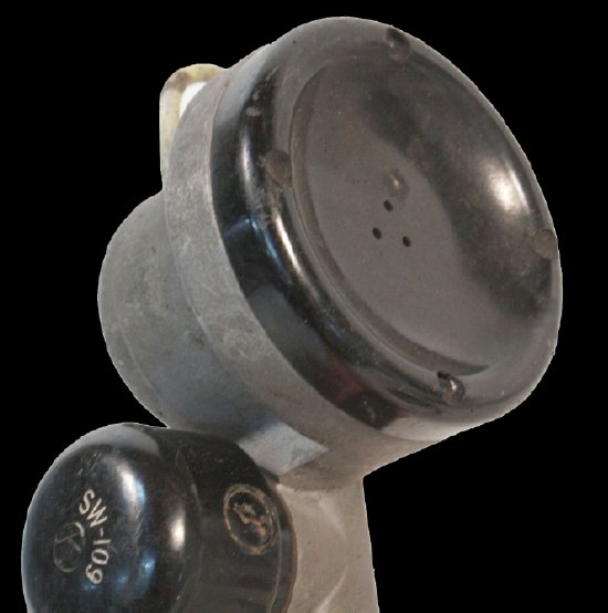
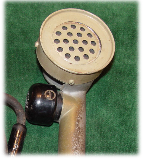
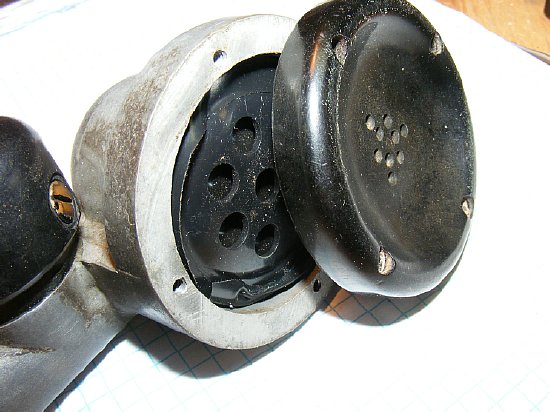
A majority of the early T-17's had 3 very small holes in the center of the outer cover.
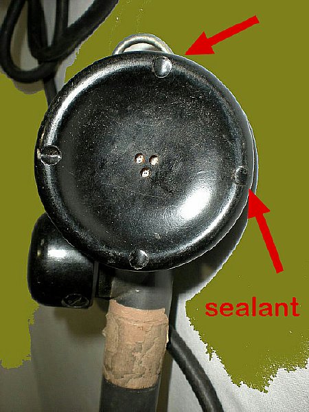
This
T-17 CHI-42 has slightly larger center voice holes. Holes were approximately
3/16 inch. You can tell if a cover has been "ham hacked" if
the black sealant is missing from the cover screws.
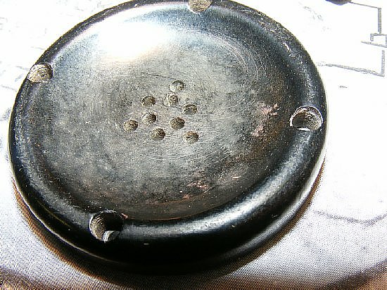
A typical ham modification. Originality 3 and changed to 9 slightly larger voice holes.
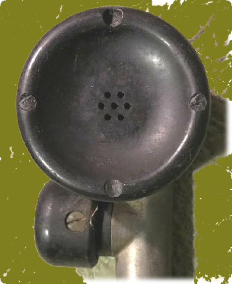
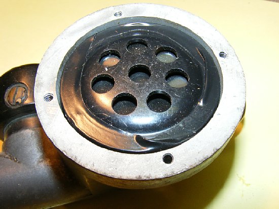
This WF-42 had 7 smaller holes.
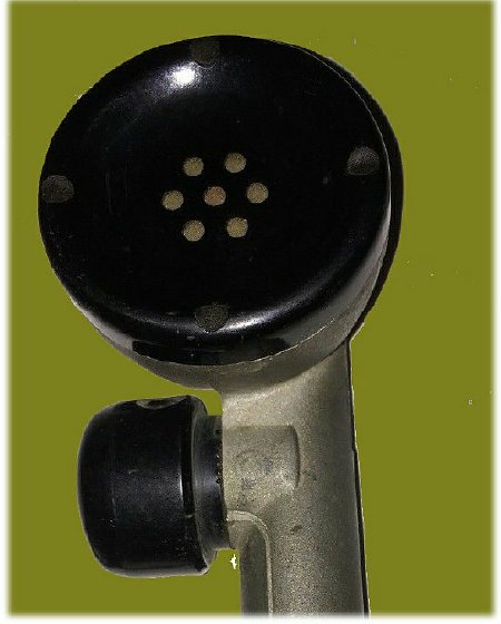
This PHL-44 model had 7 larger holes.
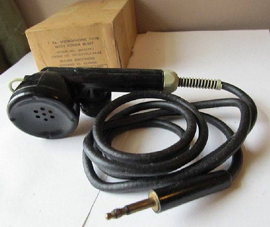
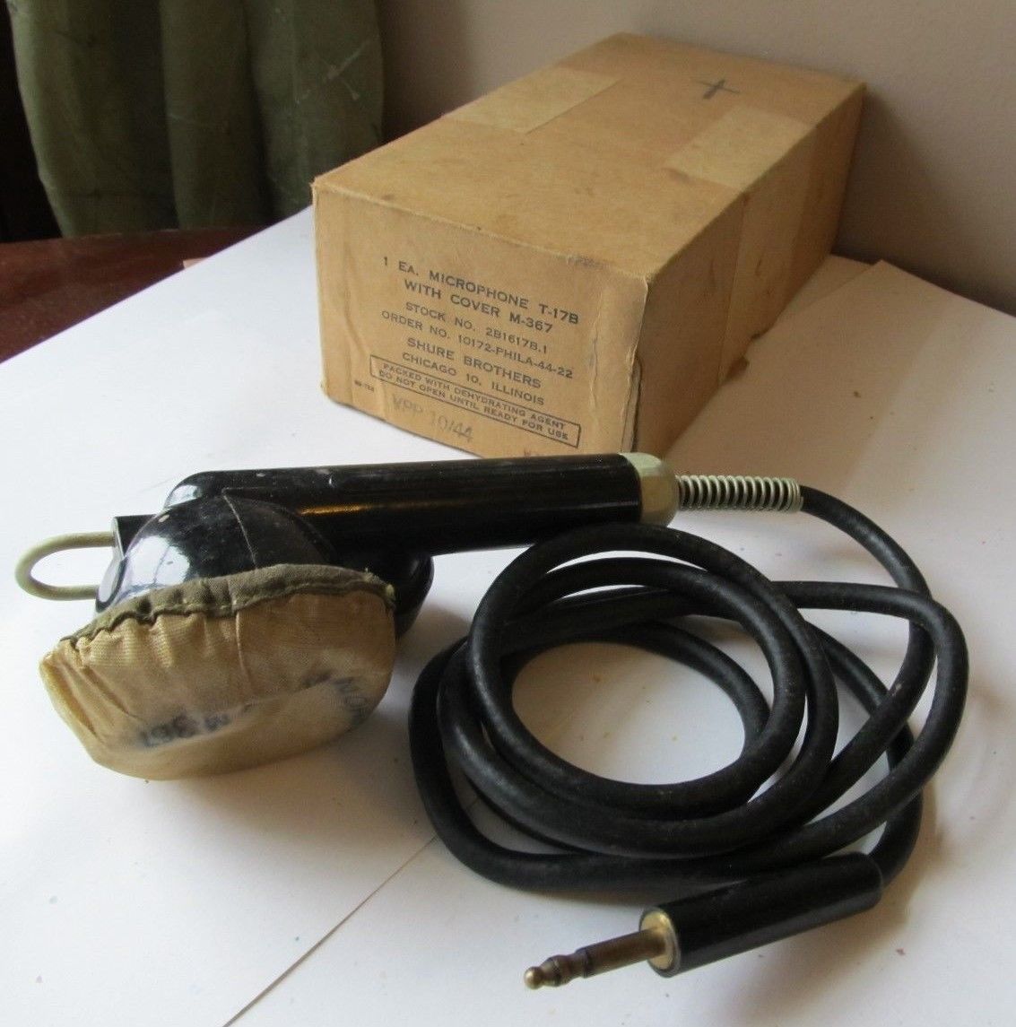
This NOS out of the box T-17 B had 7 large holes and came with the M367 cover. Info on the box indicated a manufacture date of 1944 and the location Chicago.
CLICK
to enlarge
Click
to enlarge the photo to take a better look at the box information.
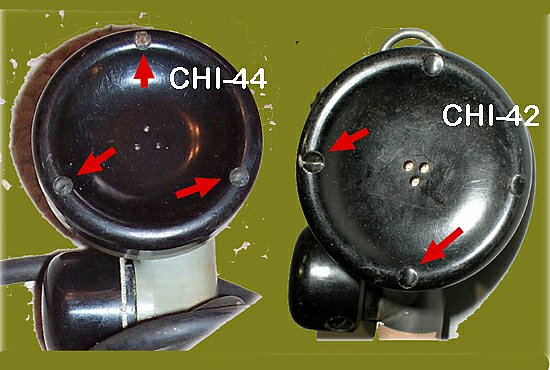
And speaking of holes the number of mounting holes for the cover changed with some of the different manufacturing locations.
Standard mic hook installed in the k4che "Operations Center".
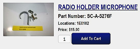
One
source of the standard T-17 hook is TNJ Murray a military vehicle dealer.
CLICK to enlarge. TM
11-2733
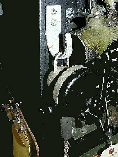
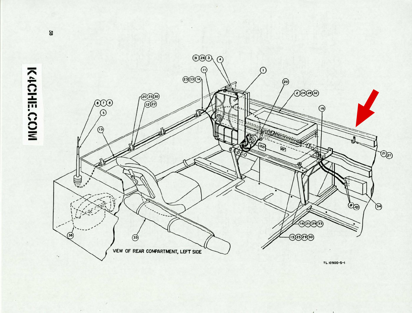
A typical mobile installation of a BC-1306 and a T-17 Mic hook installation in a M29 Weasel.
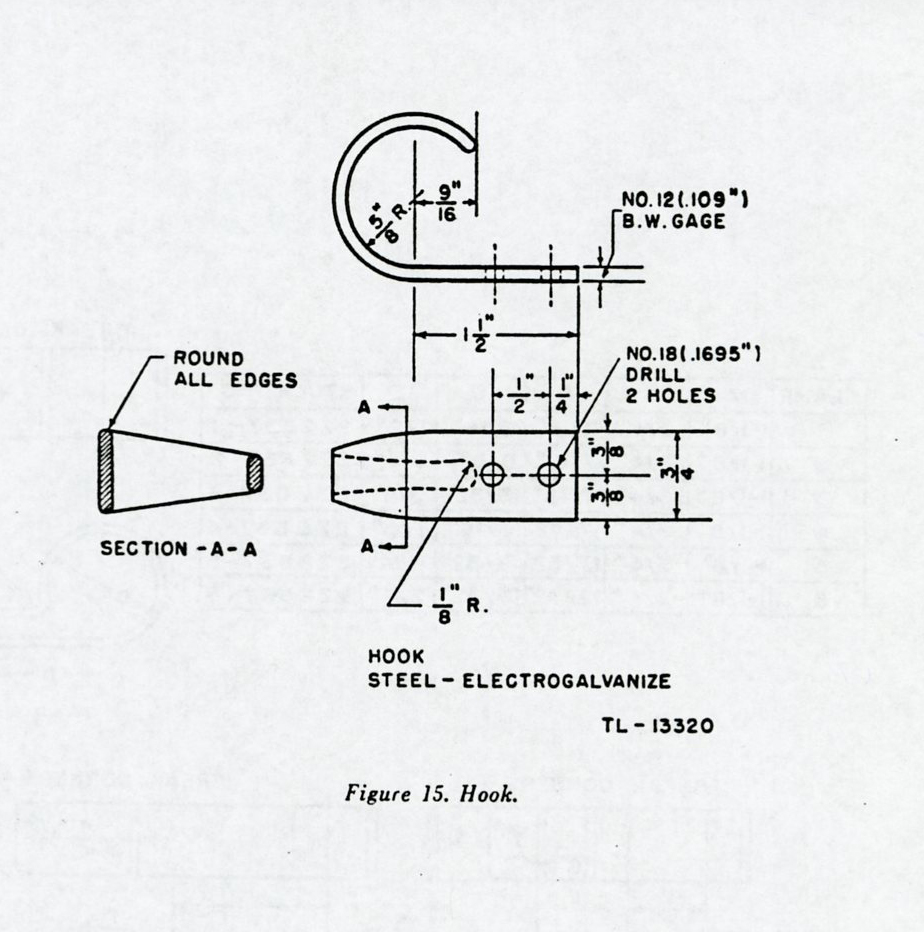
CLICK to enlarge. Figure 15. Hook.
TM 11-2733 Fig 16, page 47
AAFRadio
Photo
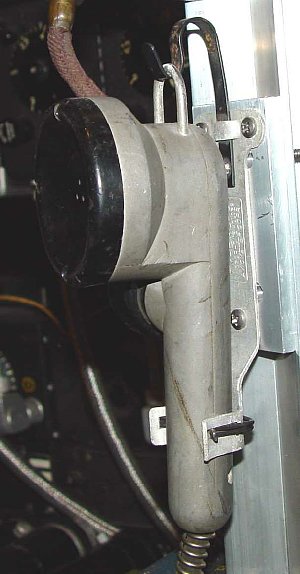
Another
more sophisticated T-17 holder.
a. The T-17 utilized as a Cockpit Hammer came in handy to break loose a window latch after landing or to loosen a stuck "Eyeball Vent" at altitude. During flight a quick bang with the T-17 on the panel of that hydraulic A-3 autopilot will often cure a sticky servo.
b. Cockpit Signaling Device. Often used on long over water flights when crew members are not on innerphone. Hold the mic and bang the side of the control column. 3 bangs means don your headset. Repeated banging means Wake Up.
c.
Handy "Extend Your Reach Gadget." Often using the hang up hook
to to flip toggle switches on the overhead panel when they just out of
reach and you do not want to remove seat belt. On certain aircraft be
careful of the feather toggles.