
INDEX Click to Navigate
Battery
Compartment switches - Read this first.
Transmitter Bench
Power up - Pin numbers, voltages and tips
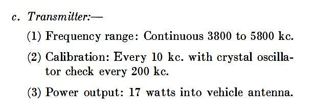
Transmitter
conversion 80 meters - Lower 80 Meters conversion.
Calibration
Oscillator - Improved operation and fabricate an adapter.
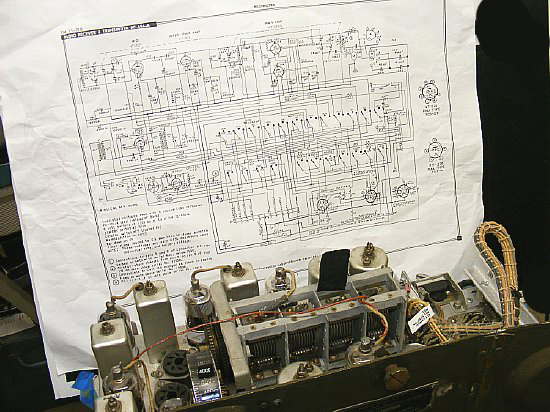
Do
you self a favor and take your schematics and wiring diagrams to a near
by copy place and make "Large Copies".

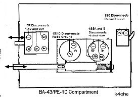
The BC-654 has a compartment that houses either the BA-43 Battery or the PE-104 vibrator supply. The battery or power supply provides low voltage filament power (1.5V) and 90 volts for the receiver and parts of the transmitter and also provide transmitter bias. The manual calls this door the "Battery Door".
Several
spring loaded mechanical "Interlock" switches are mounted under
the square cage that holds the Battery or PE-104. The switches can
be a major problem with powering up the set.
All switches are activated by doors except for the large switch 1S6 in the rear. It is activated when the radio is inserted into the cabinet.
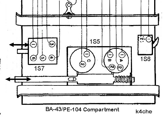
The small battery compartment door activates the spring loaded dual section switch 1S5 when the battery door is fully closed. Closing the main cabinet door for transport (it folds down) will activate spring loaded 1S7. See below.
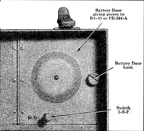 |
|Battery Door
NOTE: Photo depicts home brew rails for the PE-104 or BA-43.
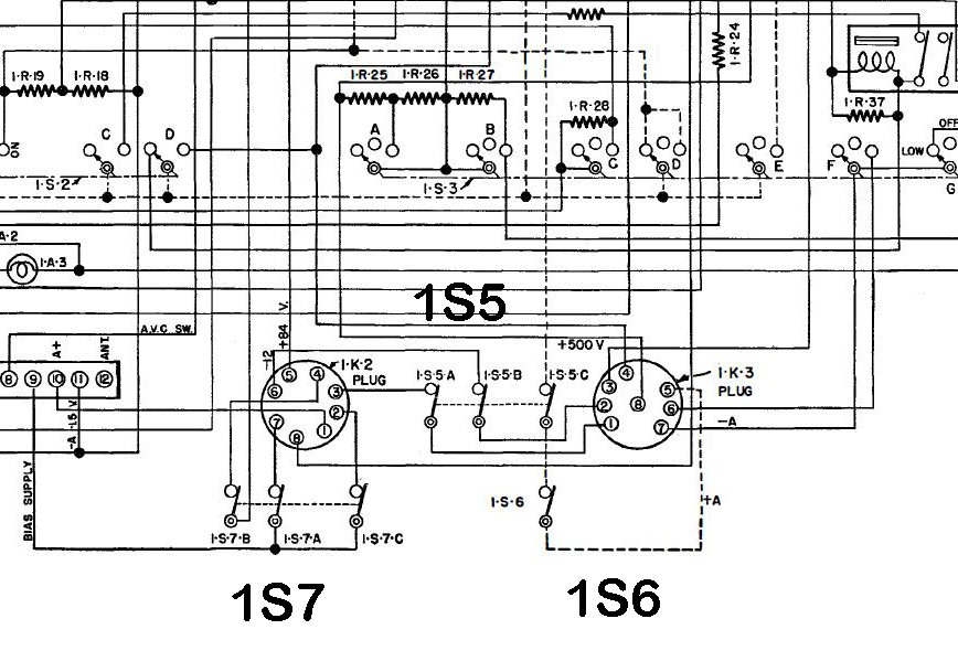
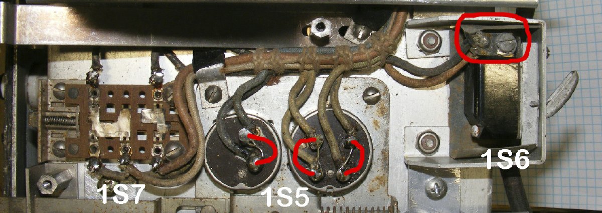
The "Shelf Switches" are very busy and control major voltages in the set.
CLICK
to enlarge
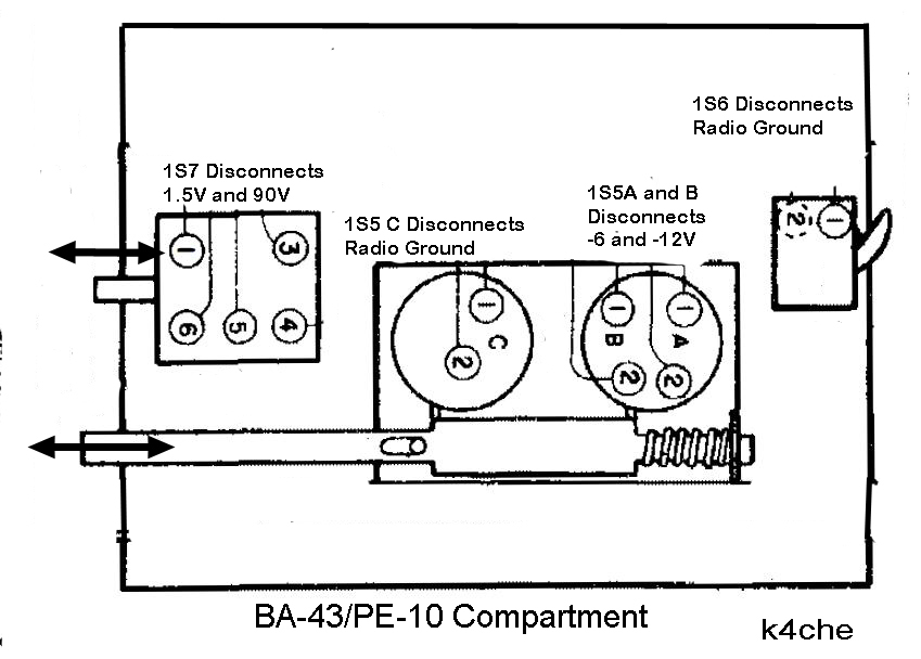
1S7- activated
by small button in the compartment door. Disconnects battery.
1S5 C- Activated closed by closing
the compartment door. When the door is opened it disconnects Radio Ground.
1S5 A and B- Switches close
by closing the battery compartment door. When the door is open switches
open and low voltages -6 and -12 volts are disabled.
1S6- Activated by inserting
the radio into the cabinet. When the set is positioned securely into the
cabinet the switch is closed and Radio Ground is connected.
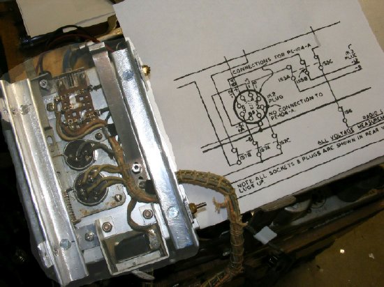
TM 11-275 Figure 17 CLICK to enlarge
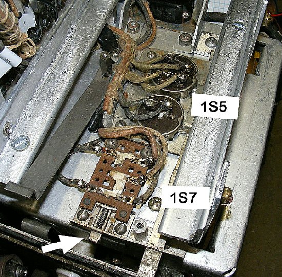
1S7 is activated by a door push button mounted in the Battery Door. Both sections of 1S5 are activated by closing the battery door. Confused yet? Note in the above photo that the side rails that hold the battery or PE-104 were fabricated. The set got "ham hacked" and is missing the square battery cage.

Q.
Why all the info on these switches?
A.
No switchee no workee.
Q.
Why not just jumper the switches while on the bench.
A. Good idea.
I left my jumpers on all the time. See below.

Battery
Compartment Switch CAUTION.
CLICK to enlarge

1S7 is activated by a Push Button/bracket attached to the compartment door. When the door is closed the push button is in position to activate 1S7 but the button must be depressed for switch action. 1S7 does not interrupt the circuits unless the set in the cabinet and the main fold down door is closed. See more info below.
When
the main desk door is closed a rubber bumper depresses the door
button for 1S7 and the battery is disconnected.
NOTE: There is no
mention of the 1S7 function in the manual. Thanks to Dave KB3ELD and Mark
KD3ZK for setting me straight.
CLICK
to enlarge
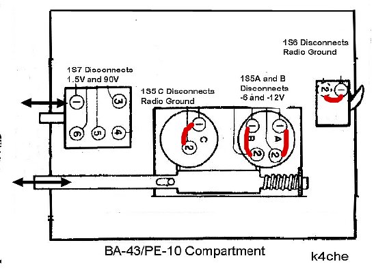
During
Bench Testing 1S5 has jumpers installed on all three sections. 1S6 has
one wire moved to the other terminal creating a closed circuit. Leave
1S7 as is.
Transmitter
Power on the Bench
![]()
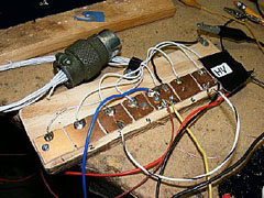
A
power break out board will assist testing and trouble shooting your transmitter.
A power strip was fabricated from printed circuit board material - the
8 pads correspond to the pins on the P8-23 cable connector. The solder
pads allow quick connections. The HV pad is covered with tape.
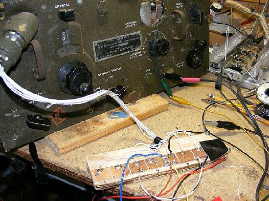
The test board provides a solid test connection to the main power connector.
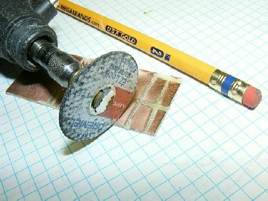
A Dremel tool can be used to create "pads" on blank Printed Circuit board material to create a test board. Search on ePay for Copper /Clad board or Printed Circuit Board.

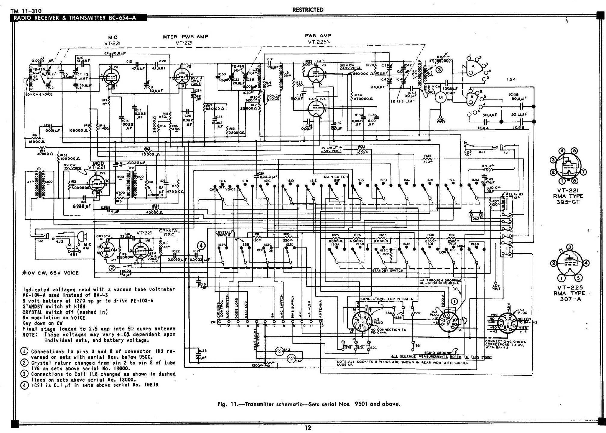
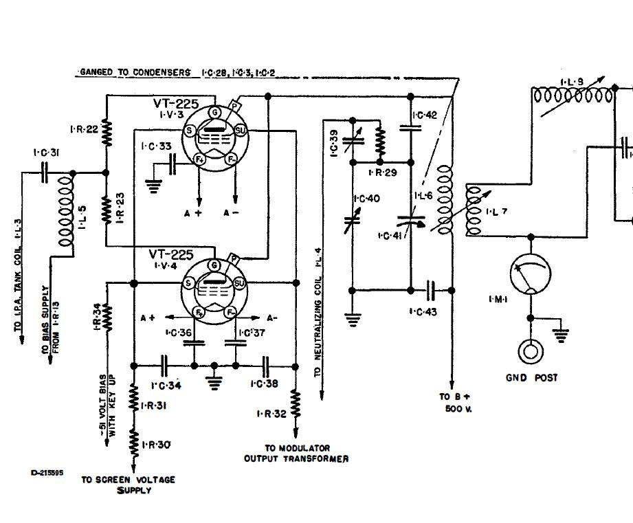
Review the schematic of the GN-45 to get familiar with basic pins on the main power connector and then go study the main transmitter schematic. Keep in mind that additional voltages have to be supplied if a "working" PE-104 power supply or battery is not installed. This includes a bias voltage for the transmitter.

CLICK to enlarge
Transmitter Power Connector Bench Test Pins
Pin 1. -6V (minus 6) Provides power to the PE-104 Vibrator Power Supply input voltage switch. The PE-104 can be powered by 6 or 12 volts and receives power via the short octal plug cable in the battery compartment of the transmitter.
Pin 2 -12V (minus 12) Provides power to the PE-104 Vibrator Power Supply input voltage switch .
Pin 3. ANT/TR Relay external power. Relay requires 6 volts.
Pin 4. Provides "Radio Ground" to close relay on PE-103 dynamotor supply. Ground provided by PTT contacts on T-17 microphone. Not needed for testing when using external bench supplies.
Pin 5. Radio Ground. Note that Radio Ground is not chassis ground. The Radio Ground is isolated from the chassis. Connect filament positive voltages, HV negative and the Bias plus.
Pin 6. - A through resistor on PE-103. Not needed for testing.
Pin 7. -6 Volts (minus 6) filament.
Pin 8. +500 High Voltage
PE-104 Cable Octal Plug Test Connections (PE-104 not plugged in)
Pin 1. Radio ground Plus 1.5V, Bias positive.
Pin 4. - 1.5V (minus 1.5)
Pin 5. Plus 90 volts HV
Pin 7. Bias minus
During
testing if you find that you have a "weak" T-17 and you get
tired of banging it on the bench then try the mods on:
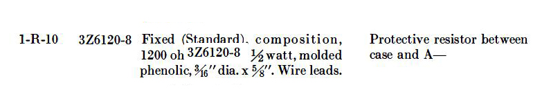
Found out accidentally that chassis is at a -6V potential due to resistor 1R10 a 1200 ohm resistor that goes from the -6 volt buss to chassis.
PLEASE
NOTE: Resistor 1R10 places the chassis at a -6 volt potential. What it
protects I don't have a clue. Just for the drill locate the resistor on
the transmitter schematic - see if you can find 1R10. ![]()

CLICK
to enlarge - - - Transmitter
Transmitter Frequency Conversion (80 Meters)
PROBLEM: The BC-654 receiver or transmitter frequency coverage does not include the lower end of 80 meters for phone and CW. The entire Extra Class Phone and CW segment are also not covered. The receiver frequency coverage is modified in Part 1 of this series. The transmitter can be easily modified by additional fixed capacitors.
Capacitors
are added to pad the Master Oscillator and RF stages down in frequency
to enable coverage of the entire 80/75 meters as well as continued coverage
above 4.0 Mc. The upper limit of coverage will be approximately 5.0 Mc.
Q.
After adding the capacitors what will be the actual frequency coverage
of the transmitter?
A.
3.5Mc to 5 Mc - The 5 Mc Upper limit is approximate depending on the set
and capacitors used.
Q.
Can I still use the Calibration Chart that is mounted on the door?
A.
No, Either make up a new chart or just make up a small chart with your
favorite frequency range or operating frequencies.
Q.
Can I still follow the alignment procedure?
A.
Yes but choose 3.5Mc and a frequency above 4.0 Mc as possible frequency
points.
Q. Will power output be effected?
A.
No. The transmitter output will still track across the 75/80 meter band.
NOTE: A small value trimmer can be temporarily soldered into place during testing. Get the transmitter stage working within the desired frequency range and then remove the trimmer and measure the value of the trimmer. Then solder the fixed value of the capacitor back into the circuit.

CLICK
to enlarge
IC5 and IC6 Capacitors are located on a terminal board near the front of the chassis and are easily accessible.
IC5
- Add a 40 pf capacitor across the capacitor to lower the frequency of
the main tuning tuning capacitor utilized in the Master Oscillator.
IC6 - Add
a 33 pf capacitor across the capacitor to lower the frequency of the variable
capacitor calibration adjustment. This adjustment is used to calibrate
the Master Oscillator.
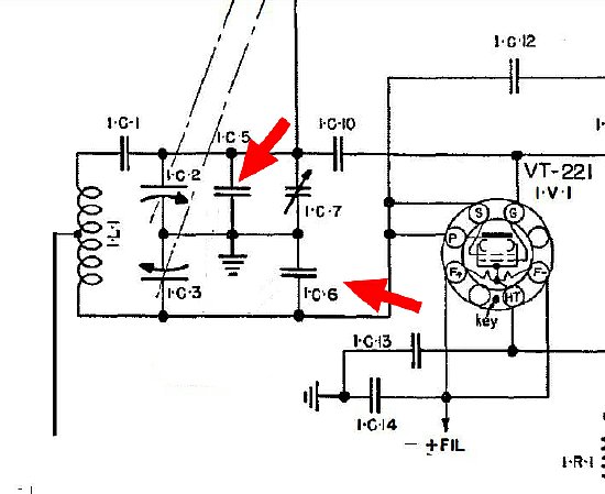
IC5
is used in the Master Oscillator circuit. Solder a 40 pf across this cap.
IC6
is used in the Calibration adjustment circuit. Solder a 33 pf across this
cap.
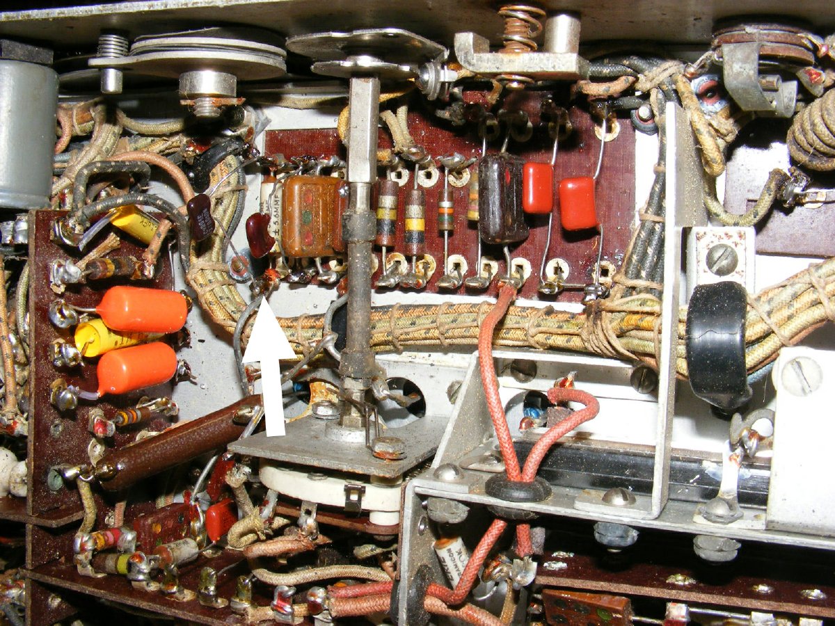
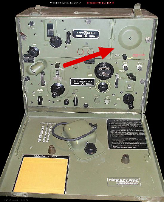
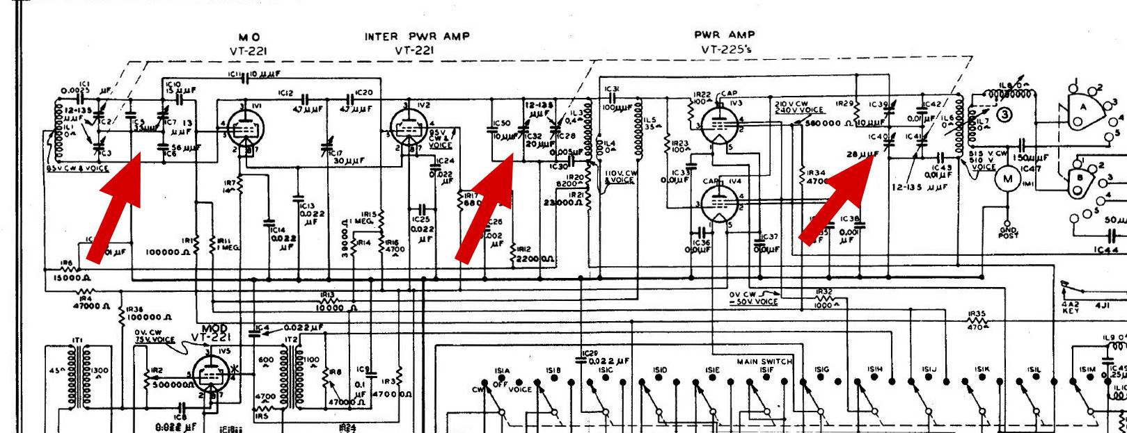
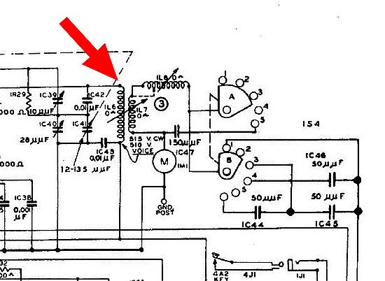
CLICK to enlarge
Arrow points to the area where additional capacitors were added.
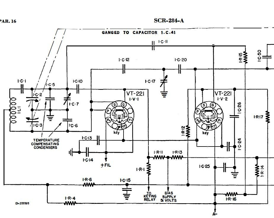
CLICK to enlarge
Progress Check: The PP voltage at coupling capacitor IC11 should be around 4.5 to 5 volt PP and remain constant as you tune the Master Oscillator across the entire 75/80 meter band.
Next the Intermediate Power Amplifier Output Stage
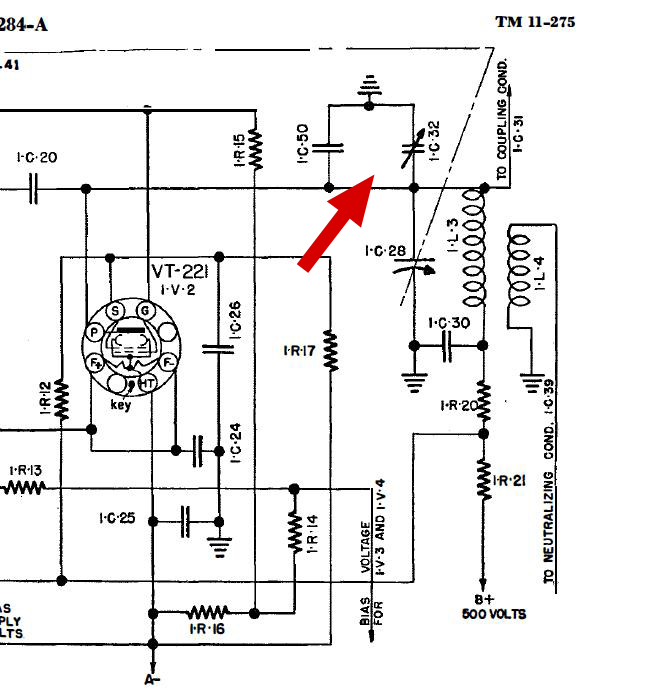
CLICK
to enlarge
IC32
a trimmer capacitor used in conjunction with main tuning is the next target
capacitor to be padded in the conversion process.
IC-32 is mounted near the rear of the chassis and is easily accessible. A 39pF capacitor is added across this trimmer. The trimmer will still function and can be used during alignment.
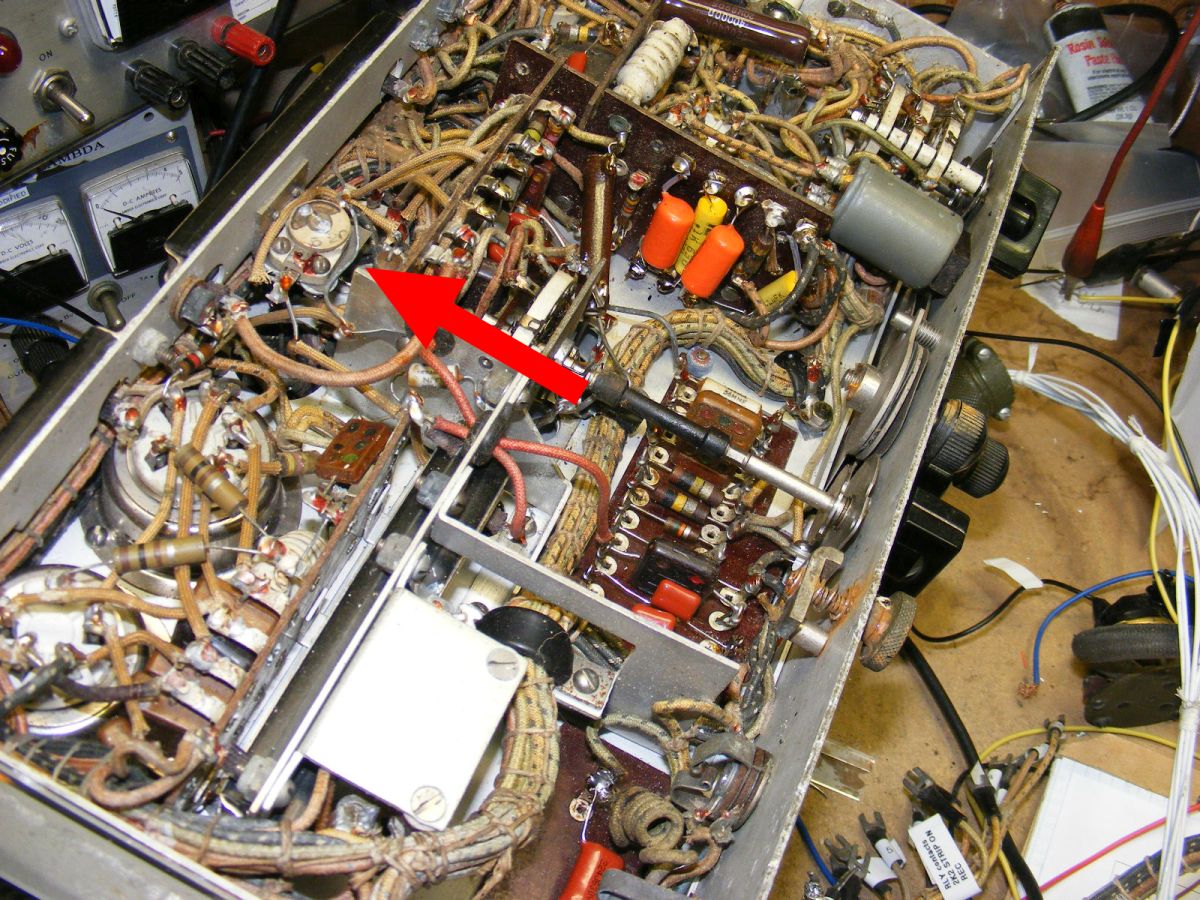
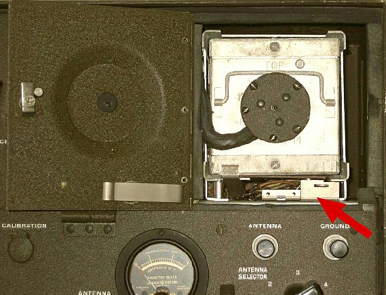
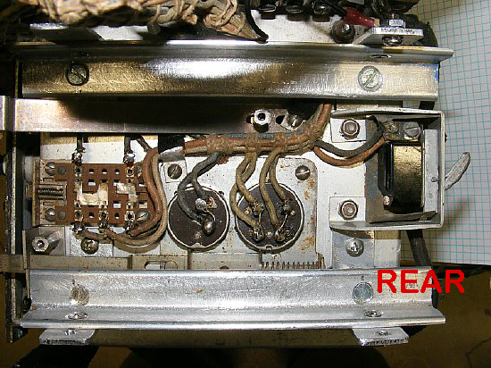
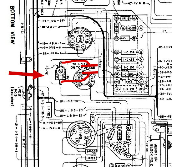
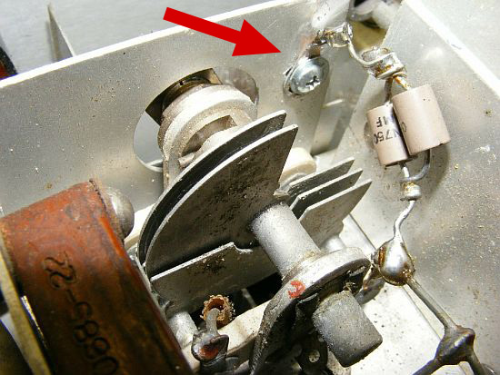
CLICK to enlarge
Trimmer IC32 is mounted at the rear of the chassis.
Solder
a 39 pF cap across the IC-32 trimmer. The trimmer still function and can
be used during alignment.
CLICK
to enlarge
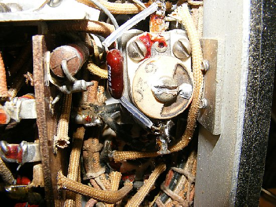
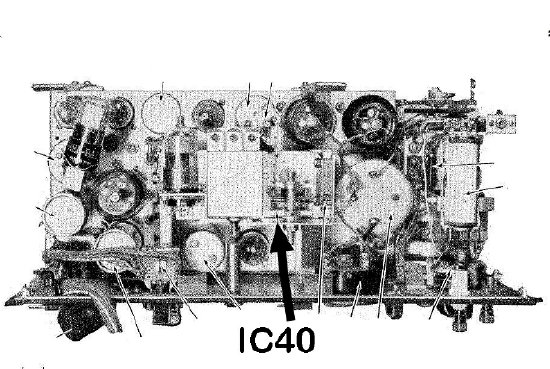
IC40 can be
padded with a fixed value to lower the tuning range for the PA.
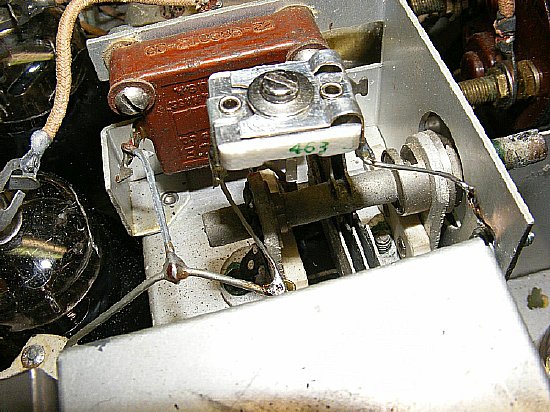
A
temporary trimmer capacitor was soldered in place when testing the PA
tuning to find a value for the fixed capacitor to pad the circuit.
NOTE:
A solder lug was attached to the chassis for attachment of the fixed capacitor.
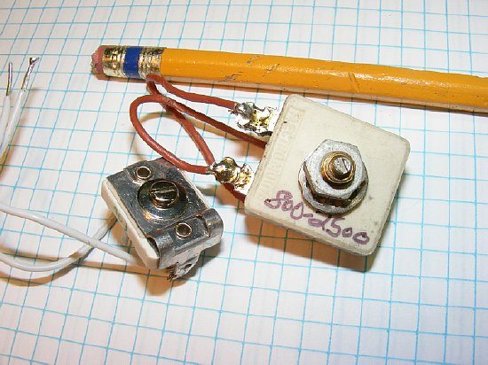
Shown
above two capacitors* in parallel for a total of
30 pF placed from IC40 to chassis ground. Ceramic HV capacitors were used.
600 volts capacitors can be used by placing two 600/60pF volt capacitors
in series. The result would be 30 pF but the voltage rating would be doubled
to 1200V. Using a total of 30 pF allowed the variable IC40 to remain at
half approximately half capacitance when the circuit was aligned. ePay
has a lot of listings for High Voltage Capacitors.
* Two
capacitors were used to arrive at 30 pF as that was what was in my capacitor
box.
The variable inductor circuit 1L6/1L7 does not require any modification and can easily cover the 3.5 Mc range.
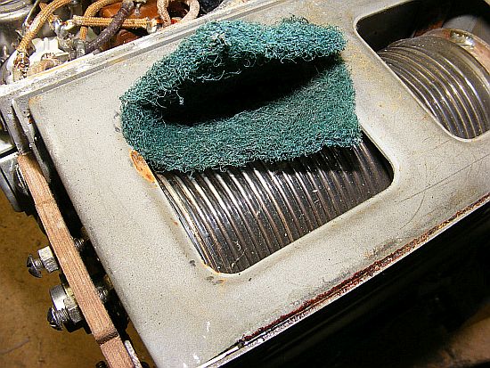
TIP: Clean the Roller Inductor using a 3M pad prior to RF testing.
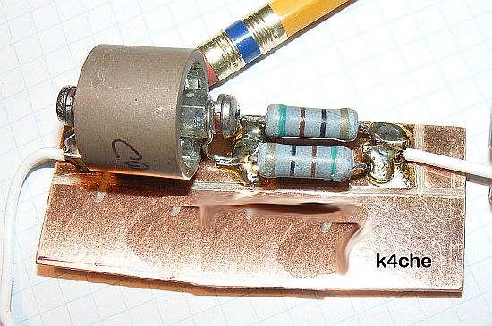
A test jig dummy load for the transmitter. The TM calls for a 110 pF capacitor and a 8.75 ohm resistor. I used a 100 pf and 25 ohms as that was what was handy in my parts box. Using the above circuit I was able to load the transmitter and check the RF amp meter for a indication (approximately half scale). This "Phantom Antenna" load works fine on other sets such as the BC-1306, GRC-9 etc.
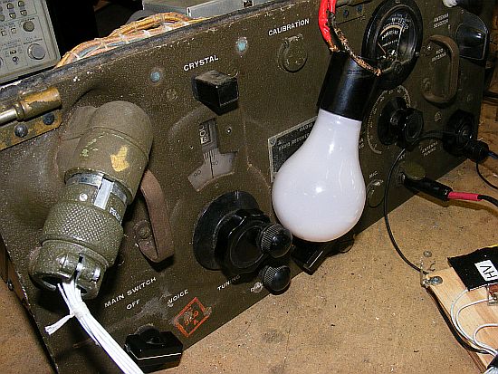
A 60 Watt bulb works fine as a test load for the transmitter. Don't use a lower wattage as the "heated resistance" of the lower wattage bulb may be out of limits for the tuning network and you will not be able to peak the transmitter for maximum output. . A higher wattage such as 75 or 100 will work OK. Due to the impedance mismatch you will only get a small indication on the RF amp meter.
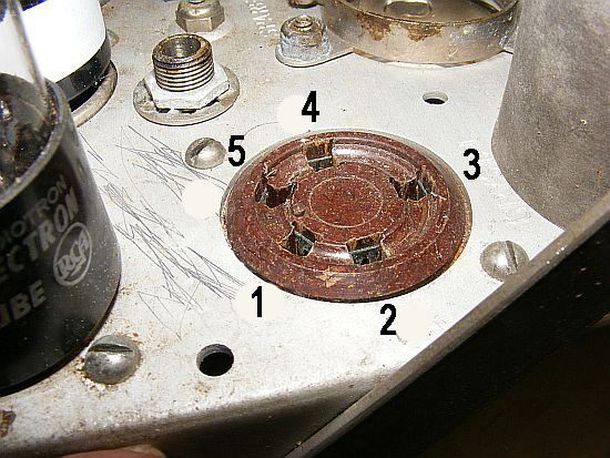
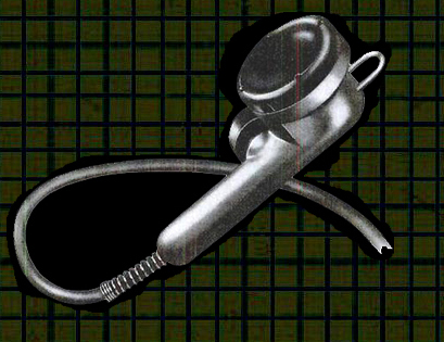
The Crystal oscillator uses a 5 pin UY socket which would accommodate several different types of crystal holders.
CLICK
to enlarge
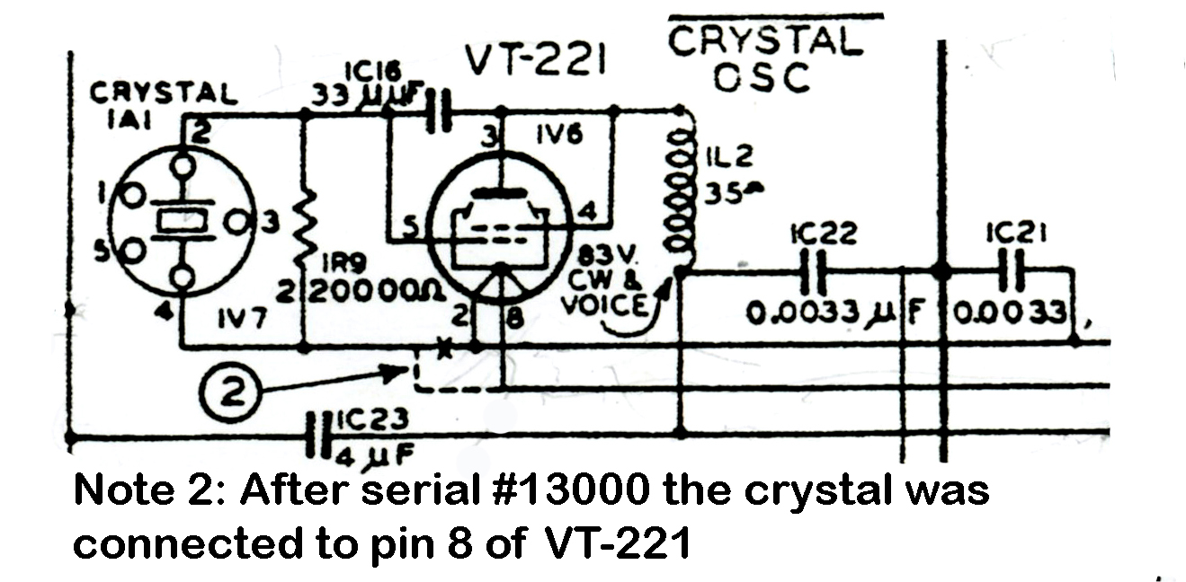
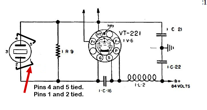
"Oscillator Coupling to the receiver is through one filament lead, which is not by-passed". Weird and on most sets the injection is inadequate. You usually have to disconnect the antenna and reduce receiver signal/noise in order to hear the oscillator 200 kc check points.
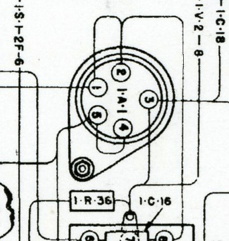
The transmitter crystal socket has pins 1-2 and 4-5 tied in order to accommodate different crystal holders. (Pin 3 is used as a convenient tie point for a chassis ground and is not used in the crystal oscillator circuit.)
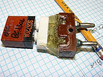
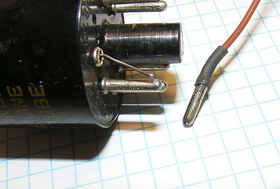
Missing the crystal adapter? My first adapter utilized the bottom of a FT-171 crystal holder and a FT-243 socket. 5 minute epoxy held it together. Ugly.
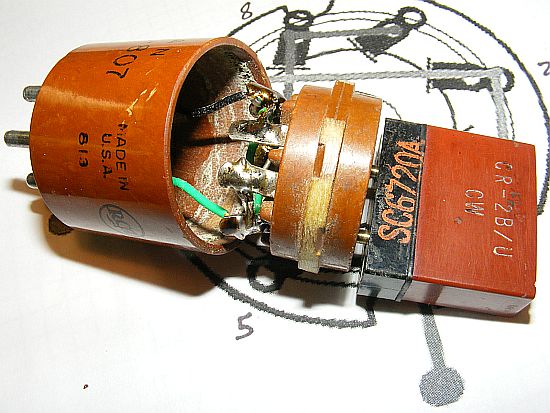
Fabricate one from a dud tube base and a octal socket. Much better idea. Thanks to WA5CAB for the tip. Test the adapter and then uses 5 minute epoxy.
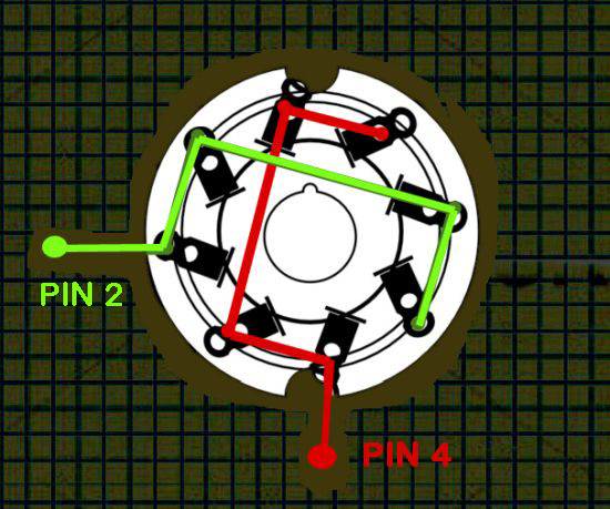
Wire the octal socket as depicted above and then connect to pins 2 and 4 of your 5 prong tube base. The crystal will be in the circuit regardless of its position in the 8 pin octal socket. You only use pins 2 and 4 of the 5 prong base.
Problem: When using the crystal oscillator the harmonics of the 200 Kc signal are very weak.
Solution: Increase the injection into the receiver.
![]()
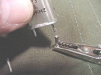
Connect
a short wire "Antenna" to the oscillator circuit on the plate
side of the crystal socket. Place the "Antenna" near the receiver.
Improvise
- Adapt - Overcome
Connect your "Injection Wire" to either pin 1 or 2 of the crystal socket.
Q.
How can I tell if the oscillator is working?
A.
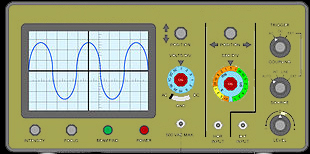
A quick check is to hold your "O" scope probe near the circuit.
Scope set on lowest voltage.
Q.
Can I hear the oscillator in a near by receiver?
A.
Yes use a piece of wire for the antenna on the receiver and place it next
to the oscillator. Listen on the broadcast band every 200 Kcs for strong
harmonics.
Q.
Can I use the oscillator single channel marker with a crystal for my favorite
frequency such as 3.570.
A.
No the oscillator will not function with higher frequency crystals.
Q.
Why all this fuss about the crystal oscillator?
A.
Why not.
Q.
I don' have a 200 Kc crystal but have a crystal for 210 Kc - will that
work?
A.
Probably and your marker will be at 3.610, 3.810 etc.
Q.
How about using a crystal for 450 Kc?
A.
You can try it but as you attempt oscillation with frequencies away from
200 Kc you may not get reliable operation.
Remove a tube pin from a dud tube and you have a socket pin for the "antenna".
BTW the tube pins from a dud octal tube base make excellent FT-243 conversion pins for HC-6 crystals.
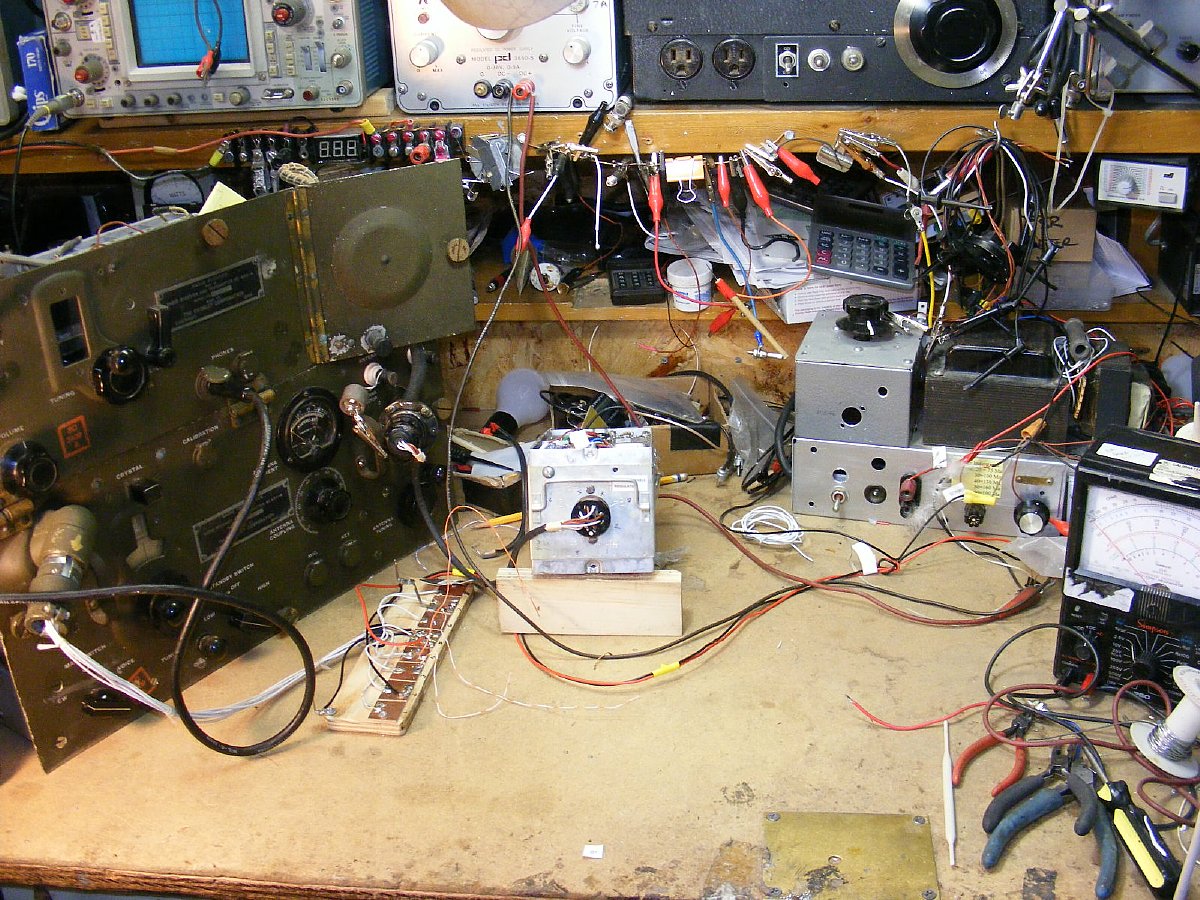
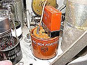
BC-654
on "Life Support". ThePE-104 supply shown in middle is connected
via a "extension cable". The PE-104 will be covered in detail
in Part 4 and probably provide you with more information than you thought
you would ever need to know. BA-43 battery power and DIY packs will be
discussed in part 3.