
SCR-284-A Part 3
Section 3 contains information on the receiver power utilizing a battery. DIY ideas are presented for a battery.
INDEX
Click to Navigate
Receiver
Power Discussion
DIY Battery
Pack
D
cells in parallel Warning.
Bias Battery
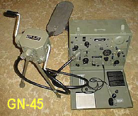
The GN-45 hand crank generator can power the transmitter and provide 6 volts to power the PE-104 vibrator supply during receive - - But when using the GN-45 it is preferred to use the BA-43 battery during receive to allow personnel to rest and reduce ambient noise.

The PE-103 dynamotor is powered by a large 6 or 12 volt vehicle battery and provides High Voltage and filament power to the transmitter but does not provide power to the receiver. It draws bookoo amps. A PE-104 vibrator supply or a BA-43 battery is needed to provide the receiver lower voltages. Confused yet?
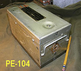
When the BC-654 set is powered by the dynamotor PE-103 utilizing a large vehicle battery the PE-104 vibrator supply is powered by the same battery. The PE-104 shown here will provide all the necessary receiver voltages as well as low voltages needed by the Transmitter. The PE-104 vibrator supply can be powered by 6 or 12 volts selectable by internal switch.
WA5CAB
photo
The
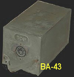
BA-43 can supply plate and filament voltages for the receiver and provide
power for the crystal oscillator and audio stage for the transmitter .
In addition the BA-43 supplies Bias voltage for the transmitter. The radio
needs either a PE-104 or a BA-43 for operation. Photo by Mr. Robert Downs
WA5CAB.
Receiver
power provided by the PE-104 or BA-43.
Filament
-1.5V
Plate 90V
Bias - On the receiver
it is approximately -6 from the PE-104 or approximately -
45 volts from the combined BA-43 battery returns of +90
and -45. This receiver bias voltage is not
critical and is used for bias on the volume/RF control circuit.
Transmitter
Power (low voltage) supplied by PE-104 or BA-43
Crystal
oscillator filaments -1.5 and carbon microphone bias.
Xtal
oscillator B +
Bias
-45V Final Power Amplifier Tubes Suppresser Grid modulation.

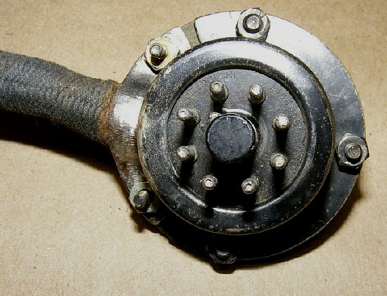
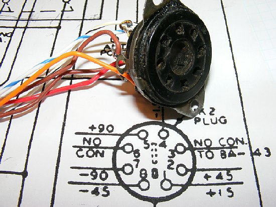
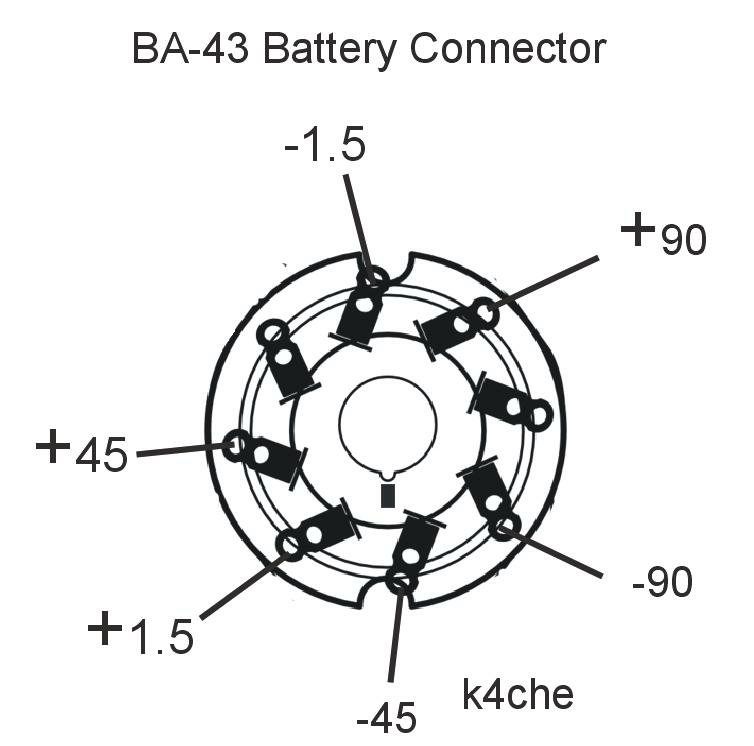
A
standard 8 pin octal plug is used for connections on the BA-43 battery
or the PE-104 vibrator supply. This is good news when fabricating a battery
or inverter supply as the 8 pin female octal socket connector is readily
available.
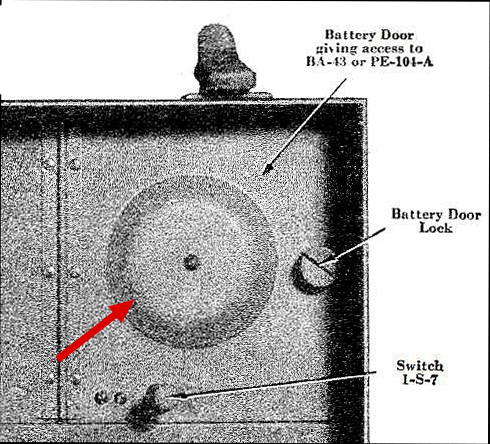
The PE-104 or the BA-43 is inserted into the "Battery" compartment. The Red arrows point to a round recessed area in the door that accommodates the octal plug housing when it is plugged into the BA-43 or PE-104. Switch 1-S-7 is covered in detail in Part 2.
The battery compartment cage is a favorite target for Ham Hackers.
militaryshop13
ebay photo
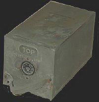
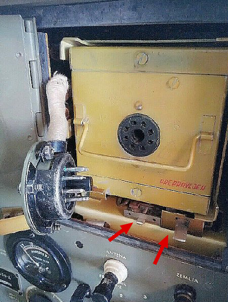
PE-104
installed. The handle is used for insertion/extraction.
Note the switches at the bottom which are discussed in Part 2 of this
series.
PE-104 and BA-43 case dimensions.
Measurements are given here
in the event you decide to fabricate a battery or supply.

WA5CAB
photo
Photo
taken by Robert Downs of a actual BA-43 battery.

WA5CAB photo
The BA-43 case has the same dimensions as the PE-104-A vibrator supply.
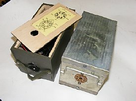
Decide on your 9 volt battery connection scheme before construction. Dimensions on your pack may not allow certain arrangements. The batteries shown here are connected battery to battery.
9 volt Batteries in this box will be mounted vertically and will utilize standard 9 volt battery connectors. Only one (1) D cell will be used and the other holder will hold a spare. I prefer using battery "Snap" connectors for each 9 volt battery - as it is easier to trouble shoot bad batteries etc.
Battery box fabricated from "aircraft" plywood purchased from a hobby distributor or ePay. The inner 9 volt batteries (5 ea) are used for bias. Sides are glued using Titebond. DIY a two evening project.
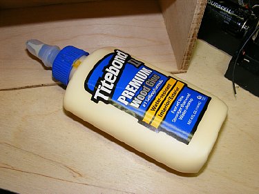
Titebond a great tool.
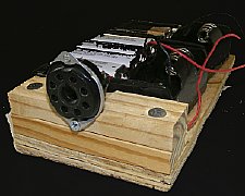
An
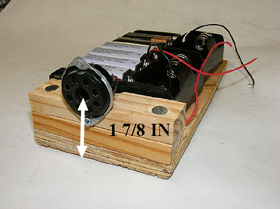
Ugly Battery Pack. 20 minute project.
IMPORTANT:
When mounting the octal socket the center should
be 1-7/8 inches from the bottom of the base.
An
ugly battery pack using a 8 pin octal socket and 1/4 plywood. D cell holders
are shown on the right of the mount. 9 volt Bias cells (5 ea.) will be
mount on top as a second layer.
Improvise
- Adapt - Overcome

A box constructed using 90 degree angle and sheet aluminum. Visit your Home supply store. Try and resist the temptation of gutting a PE-104-A supply and using it for a battery housing.

DO NOT STORE PACKS USING "D" CELLs IN PARALLEL. REMOVE ONE BATTERY WHEN THE PACK IS NOT IN USE. Monitor the pack temperature at all times. I have personally experienced and received several reports of Duracell and Energizer batteries overheating when used in parallel. The D cells develop different voltages and often one cell will attempt to deplete the other cell with resulting changes in cell chemistry occurring and a result is one battery reverses polarity.The result is a very hot battery pack and a fire Hazard. Please make sure that the batteries that you use are fresh with the same date code etc. Do not store batteries in a hot vehicle prior to use. I suggest testing the "D" cells for equal voltages under load before using them in the battery pack. I would not mix different brands of cells. Commercial battery packs with cells in parallel use fuses or other protective circuits on each battery. Best advice is to stay away from using D cells in parallel.
 D
Cells Filament Supply
D
Cells Filament Supply
Q. Will two (2) D cells in parallel provide a longer operating time for
the receiver ?
A. Yes but I prefer to just use one (1) D cell due to safety concerns. See above.
Q. When using two (2) D cells in parallel what are the precautions?
A. When utilizing D cells in parallel always remove one D cell from the pack when not in use. Monitor the battery pack temperature while in operation. DO NOT STORE your pack with the D cells in parallel.
Q. Would fusing each battery in parallel provide protection?
A. Commercial battery packs using cells in parallel have protection but like any system protective circuits can fail. In the case of a military radio such as a BC-654 or a BC-611 etc. just use one good quality D cell and keep it simple. KISS
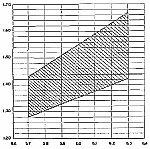
CLICK
to enlarge
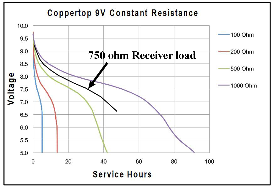
The BC-654 receiver high voltage circuits requires approximately 12 mA
at 80 to 90 volts. Current will be higher with leaky capacitors. The receiver
will operate down to 60-70 volts on the HV providing that the filament
voltage stays within limits.
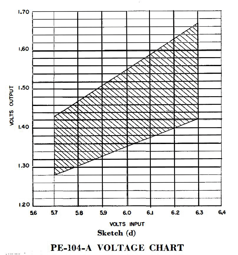
The 750 ohm line approximates the receiver load on a single 9 volt battery.
A 9 or 10 cell battery pack should last 30-35 hours and in most cases
outlast the filament supply battery.
CLICK to enlarge
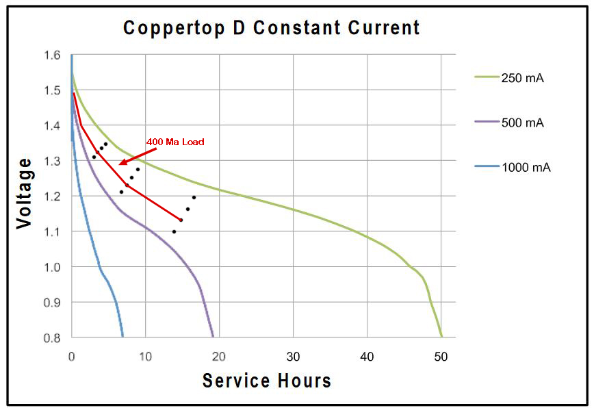
The BC-654 total current drain on the 1.5 volt filament buss is 400 mA. A single good quality D cell should last approximately 5 to 6 hours - plenty of operating time at a Military Rally.
CLICK
to enlarge.
The receiver should operate with filament voltages
as low as 1.3 volts. The nominal voltage is 1.4 volts. Receiver operation
was OK during bench testing with the filament supply as low as 1.2 volts.
During the lower voltage the receiver converter/oscillator tube
2V2 would stop oscillating and the receiver was inop. Over voltage will
result in tube life being reduced.
![]() Testing tubes. Do not test filament (continuity) with a analog VOM unless
you are sure of the voltages applied during a resistance test. Normally
you will use the low ranges of X1 and X10. My Simpson 260 was OK on the
lower ranges and used a 1.5 volt battery. On the higher ranges the meter
utilized a 9 volt battery.
Testing tubes. Do not test filament (continuity) with a analog VOM unless
you are sure of the voltages applied during a resistance test. Normally
you will use the low ranges of X1 and X10. My Simpson 260 was OK on the
lower ranges and used a 1.5 volt battery. On the higher ranges the meter
utilized a 9 volt battery.
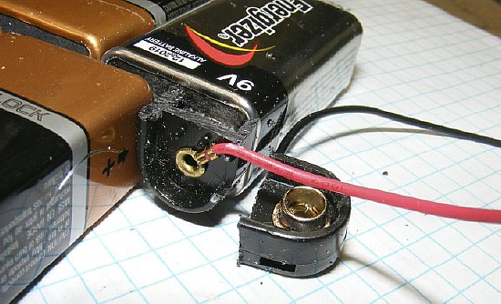
Cut a 9 volt "snap" connector in half and use for main connections on the end of your pack.
Another
alternative connector for the main connector on the battery pack.
Mouser
part number 534-271 and 534-264.
Connections
can be made direct to the octal socket or use a voltage distribution strip.
Enlarge your battery diagram to aid in the wiring task.
![]() - Don't make a mistake in wiring the filament power on pins 1 and 4 of
the connector. Don't apply any of the higher voltages by mistake to
any of the filament pins!
- Don't make a mistake in wiring the filament power on pins 1 and 4 of
the connector. Don't apply any of the higher voltages by mistake to
any of the filament pins!
CLICK
to enlarge
Octal Socket Read View
Battery connections. Note that
pins 3 and 6 are not used in the battery configuration. They are used
on the PE-104 Vibrator supply.
BE CAREFUL - Don't make a mistake in wiring the filament power on pins 1 and 4 of the connector.
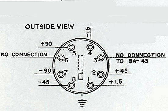
Front or outside view of the connector.
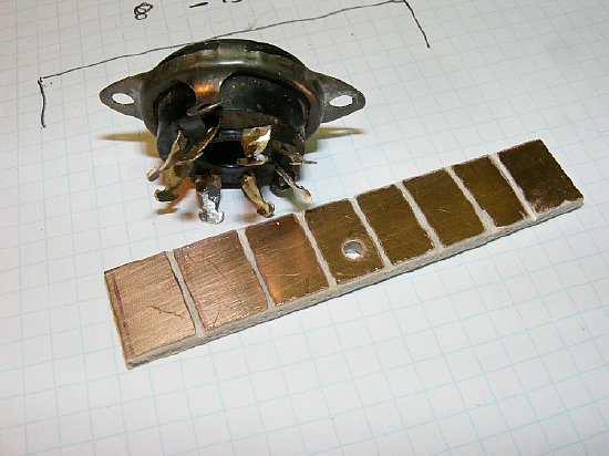
I prefer to install a "voltage distribution board for the octal socket and fabricated a strip with small pads from blank printed circuit board.
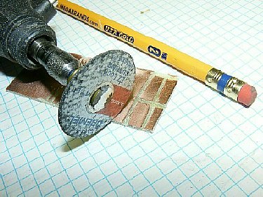
Use a Dremel tool to cut the pads.
The distribution strip makes it easy to make connections and to check battery voltages. I only had room for nine (9) batteries in the box for the HV plate supply and used 5 batteries for the Bias.
Q. The bias voltage listed on the transmitter schematic is -51(minus 51 volts) for the PE-104 but for the BA-41 battery the voltage is -45 (minus 45 volts). Is this critical?
A. No either voltage will suffice.
Q. Will transmitter output be effected by the bias voltage.
A. Yes. A low bias voltage will result in increased RF output and modulation will decrease. During bench testing reducing the bias to approx -35 volts resulted in a increase in RF output of a couple of watts with the transmitter in the High power position. Over voltage above 50-60 volts will decrease RF output.
Q. How much current does the transmitter bias circuit consume?
A. Not very much approximately .5 mA (point five milliamps). Leaky caps will result in a higher value.
Q. How long will a bias battery pack consisting of 9 volt batteries last?
A. A long time.
Q. Should I remove the battery packs from the radio when the set is not in use.
A. I would either remove the pack or else disconnect the main connectors on each pack and remove the D cell. However the BC-654 radio has disconnect switches (1S7) installed below the battery cage that are designed to isolate all the battery outputs when the main door is closed. SEE part 2.
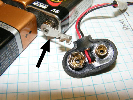
Five batteries were utilized for bias. They were connected in series with modified connectors that have the red and black wires shortened .
Connectors were modified for the bias battery series wiring. Leads were cut short and soldered.
Many battery options are available. The Exell 415A could be used for a very simple bias supply.
FINI
ready for the next rally.
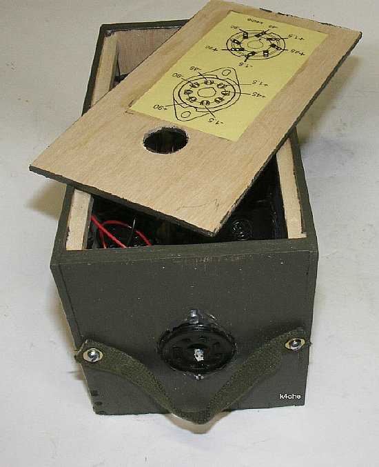
Don't forget
to attach a strap to assist in extraction of the battery box. Note the
wiring diagram has been attached to the upper lid. TIP: Glue a wiring
diagram to the inside of the top cover and then cover with clear "Con-Tact
paper available at Wally World.