 page 2
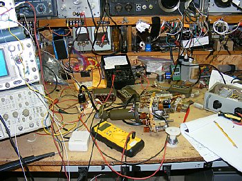
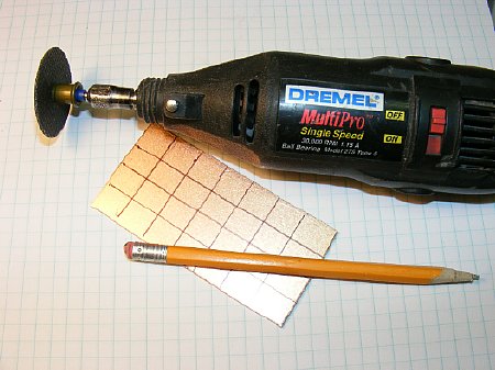
Click to enlarge
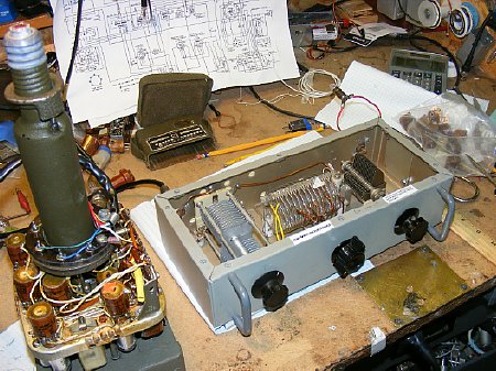
A well organized bench aids in overall efficient equipment repair and performance evaluation.
Some notes on receiver alignment.
Note: Both the left and right battery must be connected.
1. When aligning the 455 Kc IF remove the receiver crystal for best results.
2.
A rough sensitively check can be made by using your signal generator and
feeding the output on the operating frequency to the input of the receiver.
No 50 ohm load is necessary. You should be able to barely detect by ear
a 2 to 4 uV (2 to 4 microvolt) signal which is modulated.
3. Feeding a modulated
455 Kcs signal into the antenna port you should be able to hear
the 455 modulated signal down to .3mV output from the generator.
4. AGC problems
see chart below.
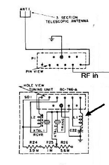
5. The manual calls
for peaking the antenna coil L1 while receiving a signal but I prefer
to transmit and use field strength. Antenna coil tuning is very sharp.
Tuning the transmitter for max field strength also tunes the receiver
input.
6. Receiver tank coil tuning is broad.
7. Selectively should be around 6 kc at the half voltage point. See chart below.
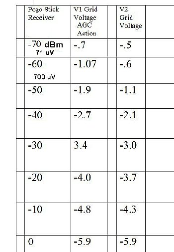
AGC voltage chart

Click
3570 kc Selectively Curve
Note: This chart depicts a curve just about identical to the BC-611 receiver.
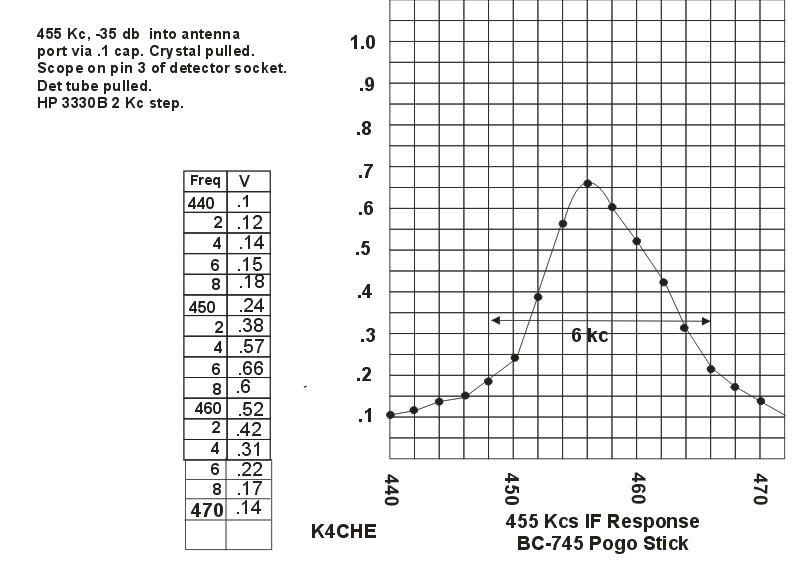
Click
455 Selectively Curve
Transmitter
Testing.
1. Make sure your filament voltage is correct.
2. Do not transmit into your signal generator.
3.Test your transmitter on an ordinal frequency before modification of any coils.
4.Monitoring total transmitter current for a dip is a good way to detect initial resonance on the bench. The goal is a nice sharp dip of approximately 10 ma, current will vary between 65 and 75 ma.
5.A type 47 light bulb load can give a rough indication of power output if properly matched. More info below.
6.When matching the whip antenna field strength is the most efficient and easiest method.

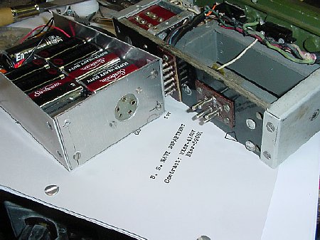
The
"break out" socket is very useful
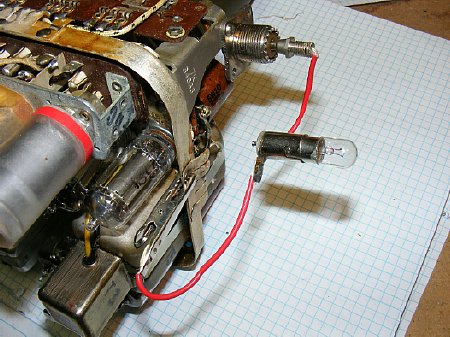
My favorite dummy load a 47 bulb. Specs are: 6.3 volts at .15 amps. Full bright represents .95 watts, half bright .45 watts. But - - -
Testing with a light bulb will require a reduction of L1 inductance. At 3.885 the inductance of the antenna coil is approx 80 uH which is too large to match the bulb. Try using some of the 5 Mc tuning unit coils which have a lower inductance and provide a good match. You need around 30-40 uH. Alternate methods of matching are shown later.
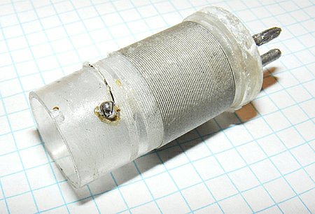
Test coil used for "light bulb" bench testing 3.5 to 4.0 Mc, turns were reduced to provide the match for the type 47 bulb for a bench check of power. With the solder tab in place it is easy to play with the number of turns.
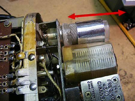
An old trick. Use a hollow thin metal tube or covering and fit it over the antenna coil. Moving the cover in and out will adjust the inductance. Aluminum duct tape formed as a tube was used for the example in the picture. Using this procedure I was able to partially match the 47 bulb using a 3885 kcs coil. But reducing the actual antenna coil inductance still provided a much better match.
Adapt-Improvise-Overcome

Click
A
simple LC circuit will match the Pogo on 3885 kc to a type 47 bulb.
The coil is 20 turns on a 1-1/2 PVC tube, I did not measure the inductance
but looks like about 10 uH. The 1 and 1/2 inch thin wall PVC is available
in the plumbing section of your local home supply. Look at sink installation
kits.
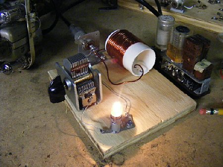
Look like about 3/4 brilliance which equates to approx. 700 mW. Transmitter current was 65 ma at resonance and the transmitter current dip was a sharp 10 ma.
A standard antenna tuner should match your light bulb for bench testing. But the simple LC circuit is more fun.
A link on matching "strange loads"
Brain Fart: I've gone to all this trouble to match different loads . Why not match the BC-745 to my 200 foot loop and use the BC-745 to attempt a check in to the MRCA CW net. Establish the MRCA CW distance record with the BC-745?
 MRCA
CW net. Sunday 3.570 kc. W3PWW net control.
MRCA
CW net. Sunday 3.570 kc. W3PWW net control.
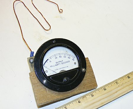
Junk box field strength meter
A simple field strength meter is the best way to match the actual whip antenna. Tuning for maximum field strength also tunes the receiver. Expect a 2 or 3 foot range using a 200 uA meter. Circuits are in any ARRL Handbook. 30 minute project.
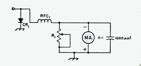
ARRL Handbook Schematic.
Simple Field Strength meter. When constructing omit R1.
CR1 1N34 diode or try any diode.
RFC1 2.5 mH choke or anything close.
Meter 50uA - 200uA for best sensitivity.
Antenna 15 inches of #14 wire.
TIP: Build one simple meter circuit, no variables, no R1, no tuned circuits. Use the same short length antenna on all tests. Use this meter on all your low power projects such as DAV, BC-611 etc. Keep notes of the distance and meter reading of each set. Easy to use for quick touch up in the Field. KISS
Brain
Fart Problem: NO BFO for the Sunday night MRCA CW net.
Emergency circuit board.
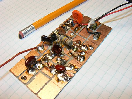
Not pretty but fast.
Click
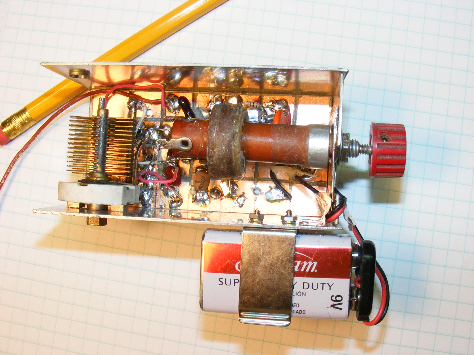
A junk box BFO
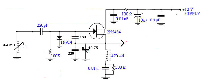
Click
I probably need to add some voltage regulation etc. I prefer to tune with the variable inductor instead of a capacitor. The Variable capacitor sets the range of the BFO and then the tuning is done by slug tuning on the 3-4 mH coil. A short piece of wire will be used to couple to the Pogo by placing it in the vicinity of the mixer wiring.
Portion of schematic was lifted from the QRP site of:
http://www.wa0itp.com/
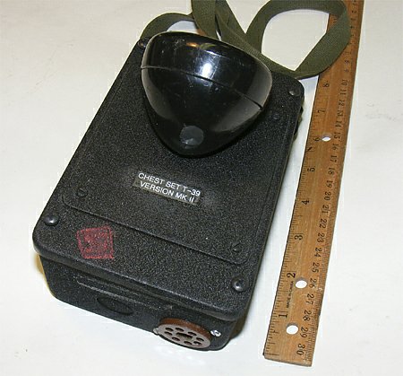
Brain Fart: No microphone-earphone interface. I need a "Chest Set" for audio and battery power so I can take this set outside and play.
Q. Why is it when working on a project that another project will spawn from the original project and then that project spawns into another project?
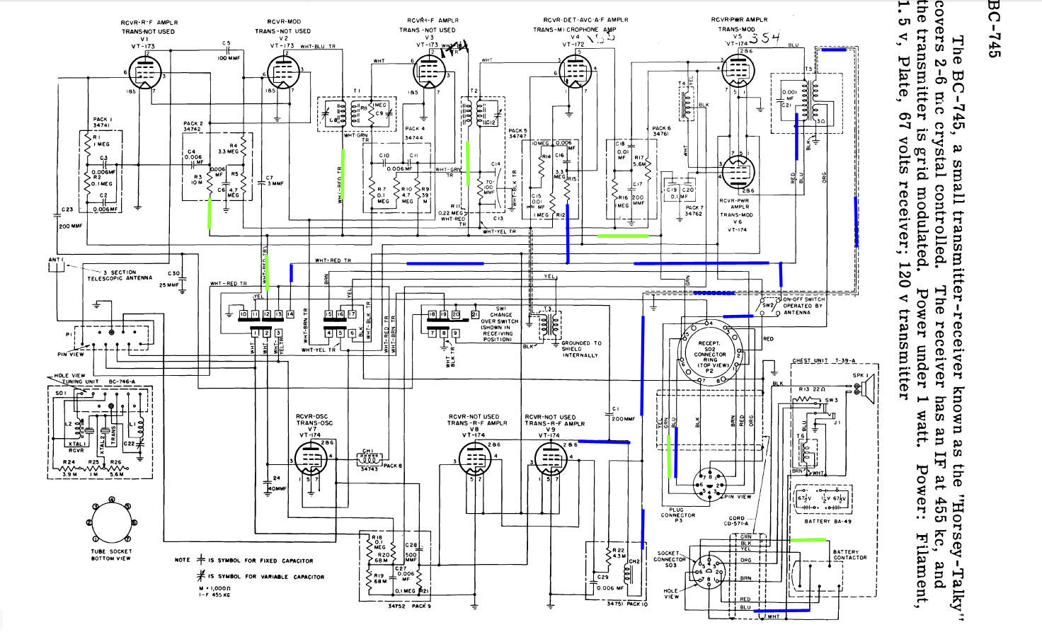
Click to enlarge. Chest set set schematic bottom right.
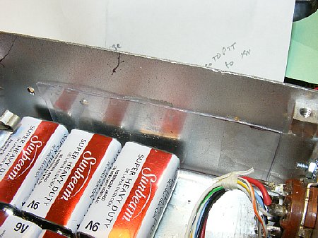
Batteries are wired to the 8 pin octal socket as per the schematic. Microphone was wired according to the schematic. I eliminated the audio transformer and resistor and just wired as per schematic. The PTT switch is used to change the speaker microphone over from receive to transmit. When earphones are plugged in the speaker is disconnected.
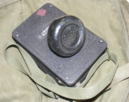
A "D" cell was used for the filament supply. I borrowed the microphone fixture from a civilian telephone handset picked up from some trash at a hamfest. The miniature Speaker inserted into the fixture was 4 ohms.
Chopping up a hand set for a microphone was invented by N3FRQ, shown above is a photo of his BC-474 set up at Gilbert. Blame him for the cannibalization idea.
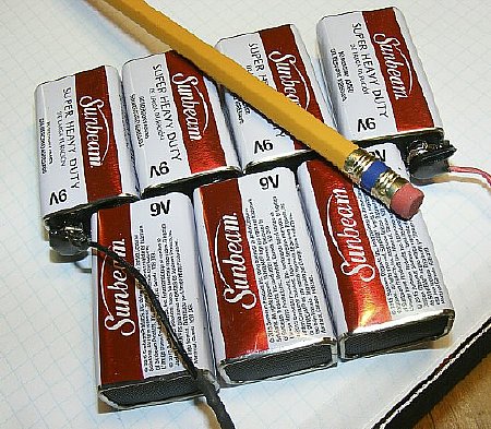
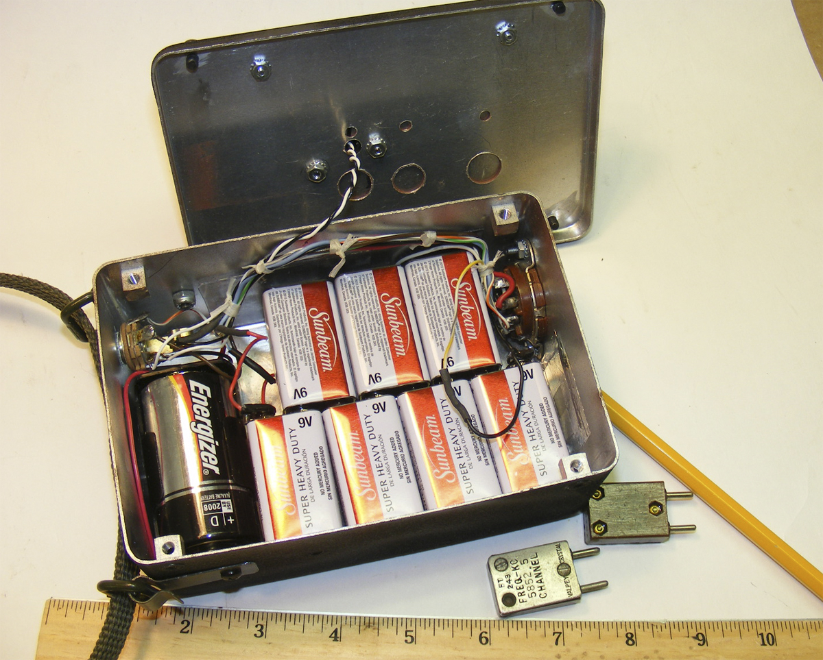
Batteries ganged in series. A battery connector was split apart for the connections on each end with a little dab of epoxy for strength.
WARNING: Any time you use 9 volt batteries for power in series - be sure and insulate the battery holder/container or case. The 9 volt battery can develop a short internally to its thin outer metal cover and then this comes in contact with the metal chassis. This has occurred several times with quality and "dollar store batteries." The brand does not matter. Never thrown a weak battery in the recycle bin without covering up the terminals with tape.
Info: I also used the 9 volt batteries in series for my DAV battery box.
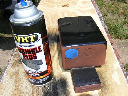
"I love the smell of black wrinkle in the morning." The local auto parts store no longer stocked Krylon but they do stock VHT and the stock number is SP201. Krylon's black wrinkle also is 201 so probably the paint has been repackaged. I got a good wrinkle with an OAT of 77 degrees so a hotter day would be even better.
A standard 8 pin octal socket was mounted on the bottom. Unit was inspected and cleared for service.
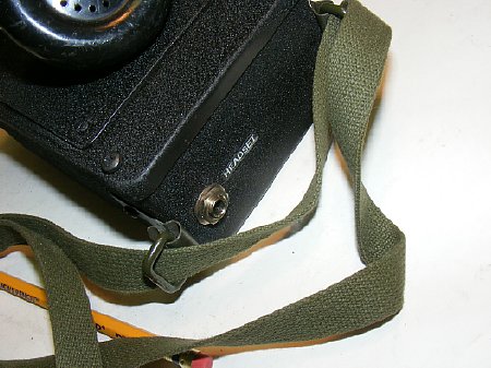
Phone jack with switch contacts was mounted on the top. When head phones are plugged in the speaker is disconnected.
Straps allow allow use while riding horse back.
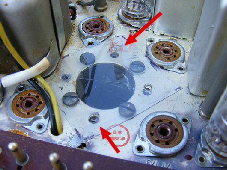
The chassis had four threaded mounting holes for the original guidon mount. I made a mounting hole pattern for use in fabricating some sort of mount. Tip: Use a piece thin clear plastic and a marker pin to help make the pattern . Cut the plastic from the front of a package or box that came from Wally World. The same plastic is also a good insulator for a battery box.
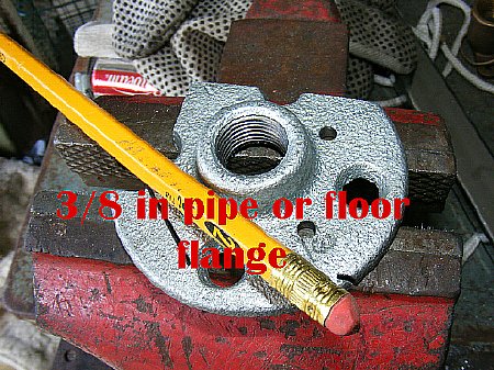
A
3/8 inch pipe flange was pressed into service and cut to fit.
Improvise - Adapt- Overcome
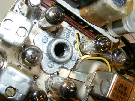
Close enough for Government work. The mod is easily reversible if and when I ever find the original mount.
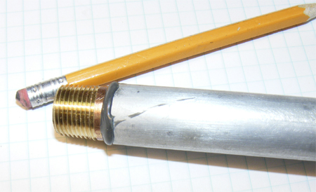
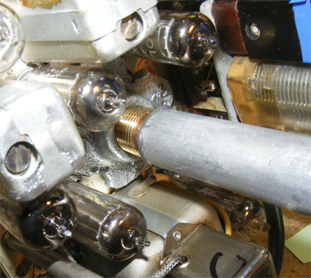
A brass fitting from the plumbing section was fitted to a 3/4 inch OD aluminum pole. It was a pretty good fit but a little JB Weld helped.
" I love it when a plan comes together."
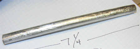
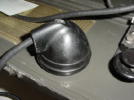
I
had an old automobile whip but needed to reduce the size of the opening
of the antenna mount as well as provide a connection to the "secret"
contact buried inside the set. A 7-1/4 length 1/2 inch aluminum tubing
was used as an insert. Note that the end of the pipe is slightly pinched
in order to clear the lower interior of the mast section. The length of
7 1/4 is necessary to reach the secret contact. .
Click
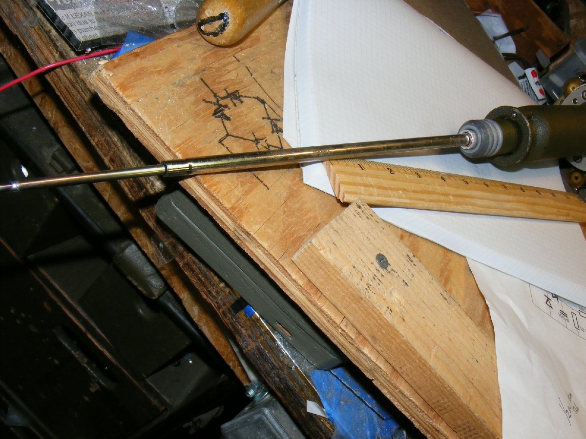
A short piece of copper tubing was inserted at the top to aid in contact with an old automobile antenna. Shown on the plywood is a handy diagram of a bridge rectifier.
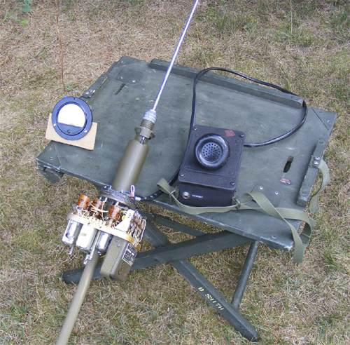
Ready for Field Strength tune up.
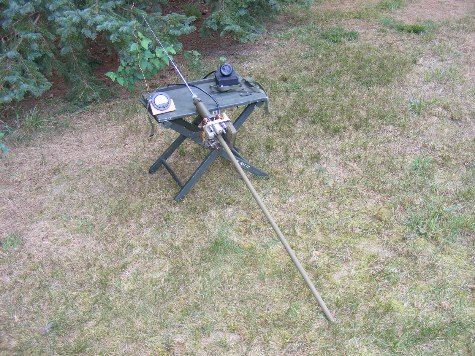
Click
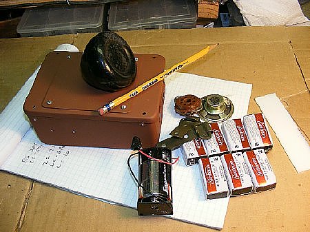
The set is missing a few bits and piece but is fully functional. Now I need a horse.
Return
to Page 1
Return
to K4CHE Index