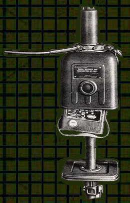
SCR-511
"Pogo Stick"
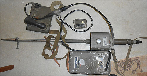
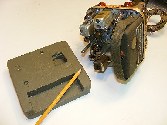
BC-745 RF Section and Chest
Set Notes
FLASH: K4CHE checks
into the MRCA Sunday night CW net with the pogo.
Click
here for video wmv
video
mp4
Click
to enlarge
Pogo set used for
CW check in.
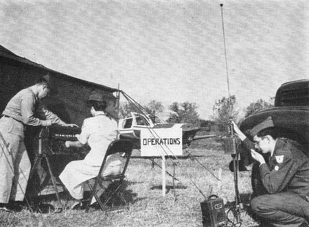

The Pogo Stick radio was very popular with the Civil Air Patrol in the 1950's. CAP was and still is a great organization. Every kid needs a boost - a direction, they gave me one. When I wound up 2 years later as an Aviation Cadet in Navigation Training I knew all about the Air Force (I thought) , close order drill, saluting, BX, chow hall,gig lines,G.I parties etc. so all I had to do was concentrate on the academics, the PT, Officer Training and Flying. A tough year.
Included on these pages.
Home
brew "Ring" connector and bench socket.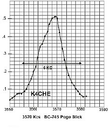
Power
requirements and breakout socket.
Antenna
info
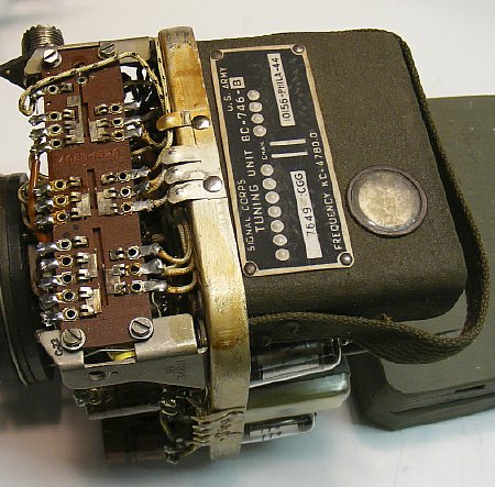
Tuning
Units
tube
location chart
Coil
mods
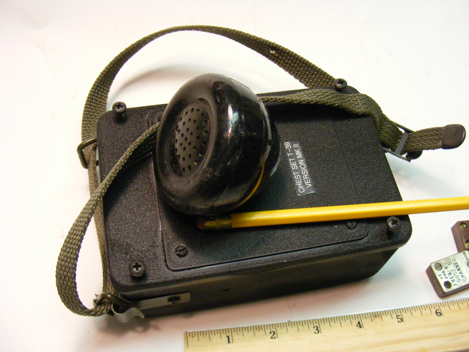
Home
brew chest set (battery and audio) (you will never find a real one.

Dave KB3ELD and Mark KD3ZK
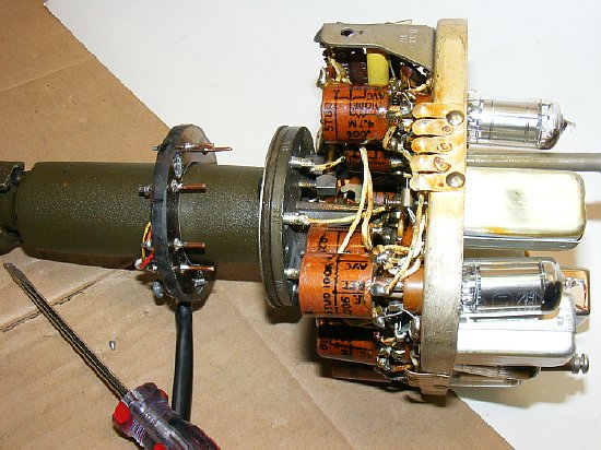
My NOS Pogo Stick RF unit (Receiver-Transmitter) BC-745 came from Dave's pile so now it has been "transferred from Dave's pile to my pile" (note below). Dave and Mark always have the most unusual and interesting WWII surplus items and are setup at Aberdeen in the Spring. Visit their flea market space and you can smell the MFP.
Note: The transfer from "My pile to your pile." Expression coined by Al, N3FRQ.
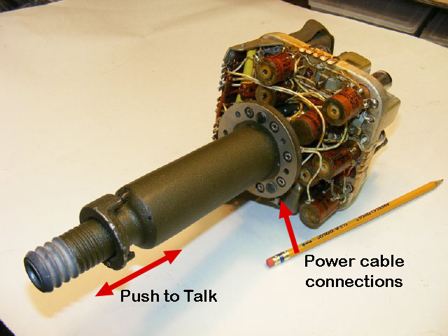
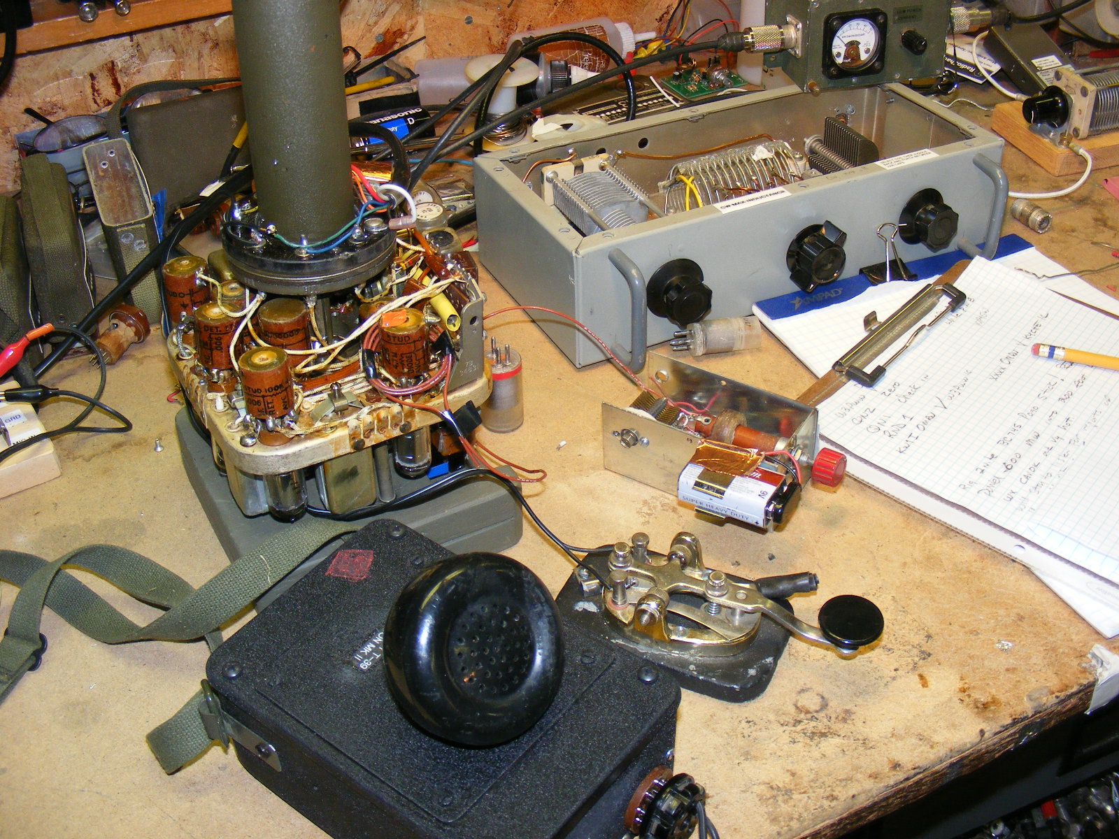
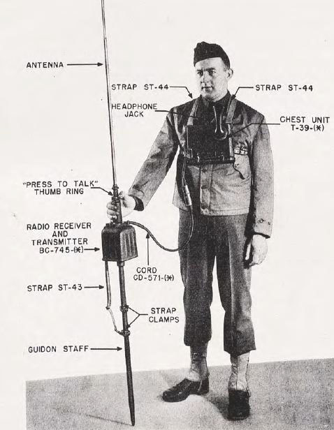
First
several bench problems - - how to provide power connections and PTT. The
unit has a very robust PTT switch you have to push down on the antenna
mast "housing" when the radio is mounted on the guidon shaft.
The ON-OFF switch is buried in the chassis and is activated by the telescoping
antenna when it is extended. Since I did not have an "original"
antenna I left the switch in the ON position for bench testing.
The main power connector consists of a very large ring connector mounted on the antenna mast with a wire cord that connects to the chest set. My supply of Pogo Stick accessories is zero and a bench "ring" connector would be handy for testing.
W3KJT photo
I don't have any of this stuff especially the chest set but pressed on anyway with the bench testing.
CLICK TO ENLARGE
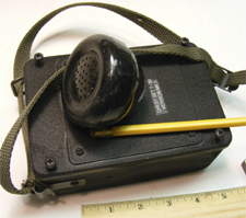
A substitute chest set which includes batteries was fabricated see page 2.Details later.
Please don't e-mail me about using portion of a telephone handset. N3FRQ did it first.
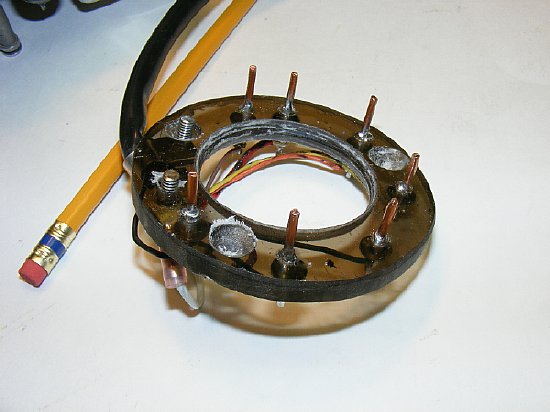
A
connector was fabricated by cutting a piece of lexan and using #12 solid
wire for the pins. A small washer and a glob of solder were used to hold
the pins in place. 3 inches OD and 1 3/4 ID.
KISS
Just a little solder and a small washer holds each pin.
The fabricated ring connector can be easily inserted or removed.
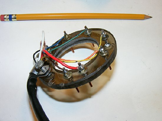
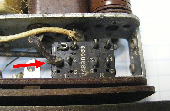
Color
coded wiring will be the same as on the schematic. The exposed terminals
help with voltage measurements.
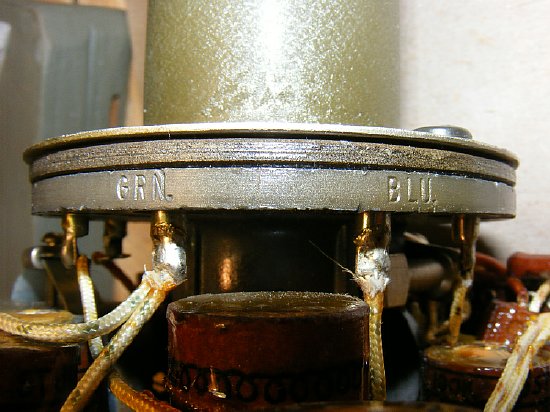
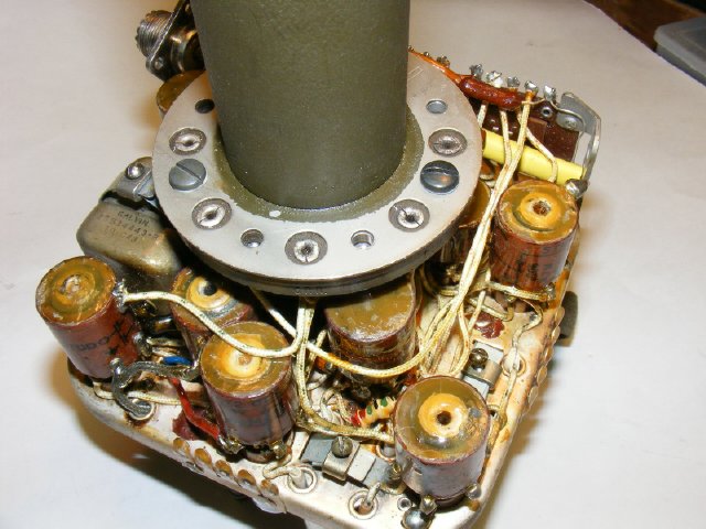
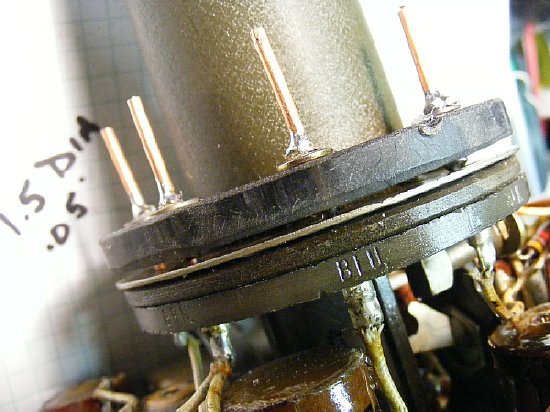
The chassis connector ring is stamped with color identification.
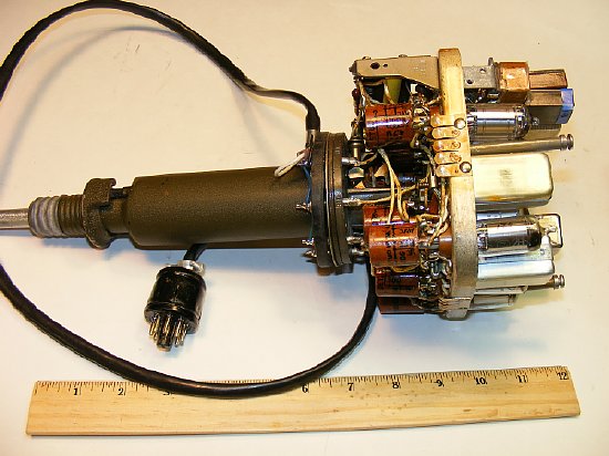
An 8 wire colored cable was used and terminated in a standard 8 pin octal plug. The cable utilizes the same colors as presented on the schematic.

A
break out socket was made for the octal plug on the "Ring" cable.
Diodes are across the filament line to prevent those little screw ups
when connected the power supplies. Instead of using my standard 1000 Volt
1 Amp Silicon Rectifier Diodes I used 1N5408 diodes which has a higher
current rating and hopefully a lower voltage drop under load. Its not
much insurance but better than nothing.
Power
connections. Note that the "left 67 volt battery" is floating
above ground.
The "Right"
67 volt battery minus side is grounded. The 1 1/2 volt filament battery
minus
is grounded.
Remember
- - The "left battery" connected to Blue + positive and Yellow
- negative must be above
ground.
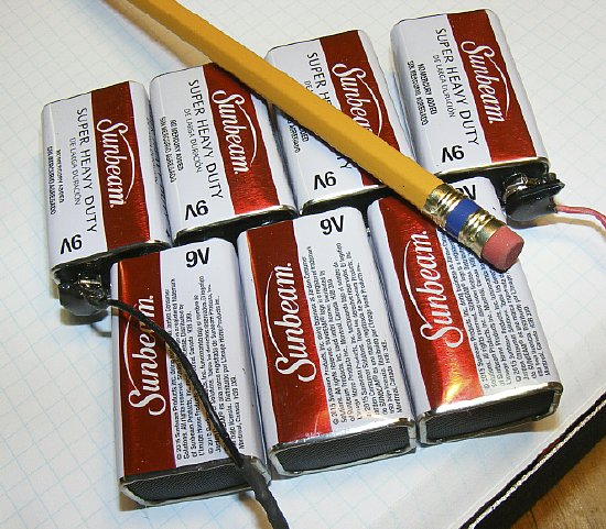
Need a quick 67 volt supply? Visit the Dollar Store. Cheap batteries and
they will make it through the ham fest and military rally season.
The
main ON-OFF switch is buried inside the chassis below the ring connector
and is activated by the antenna. During bench testing I left the switch
ON with the notched handle of the toggle switch in the UP position towards
the connector ring. This switch is old and may be intermittent.
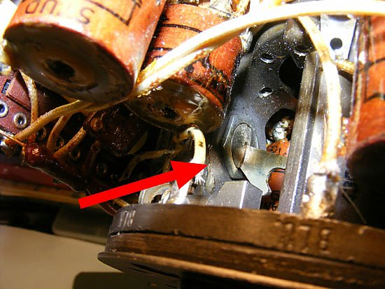
Push
to Talk is accomplished by pressing down on the thumb ring. The guidon
staff must be on a firm surface. The leggins must be laced tight and trousers
bloused properly.
PTT on the thumb ring activates this multi contact sliding switch similar to the BC-611
In
order to facilitate bench testing I disconnected the spring on the PTT
assembly. Holding the thumb ring down while testing the transmitter was
difficult.. Cover the disconnected spring with spaghetti tubing.
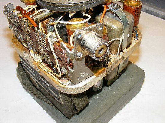
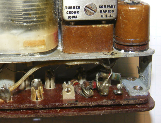
A "temporary coax" connector was connected to the solder terminal on
on the tuning unit chassis connector P1 to facilitate testing. Note the wooden bench mount.
A simple wood mount support the chassis when the tuning unit is installed.
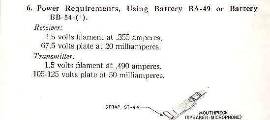
Voltage
requirements for the Pogo. On transmit two 67 volt batteries
are connected in series via the PTT switching, on receive the receiver
uses both 67
volt batteries. During PTT Filaments on V1, V2, and V3 are switched off
during transmit.
One half (1/2) of V5 and V6 is switched off during receive.
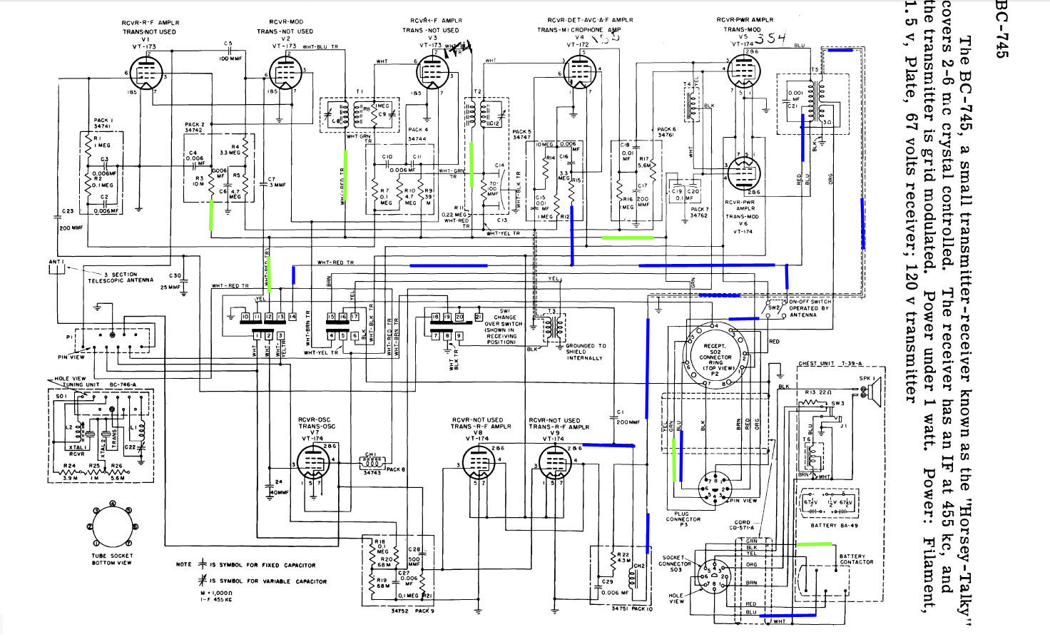
Click
to enlarge.
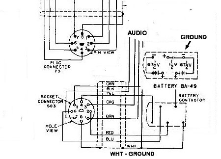
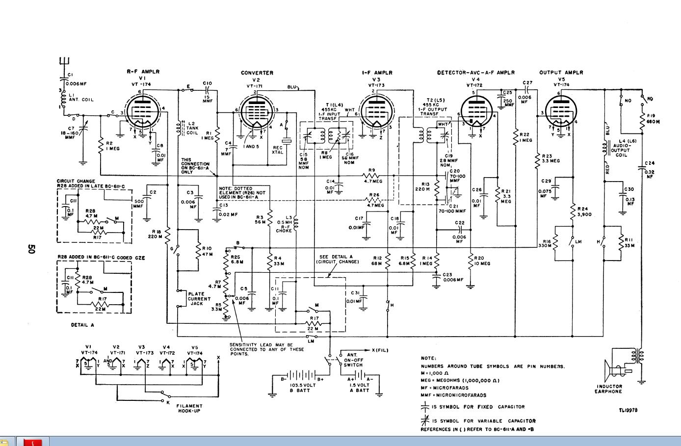
Schematic
for the BC-745 with the plus side of each 67 volt battery shown in color.
Please note that the receiver requires both 67 volt
lines powered in order to function. Receiver tubes require 67 volts and
V1,V2,V3(RF-IF) and well as V7 (Osc) are powered by the "right
battery". Receiver tubes V4(Det) and V5-V6 (audio) are power by the
"left battery".
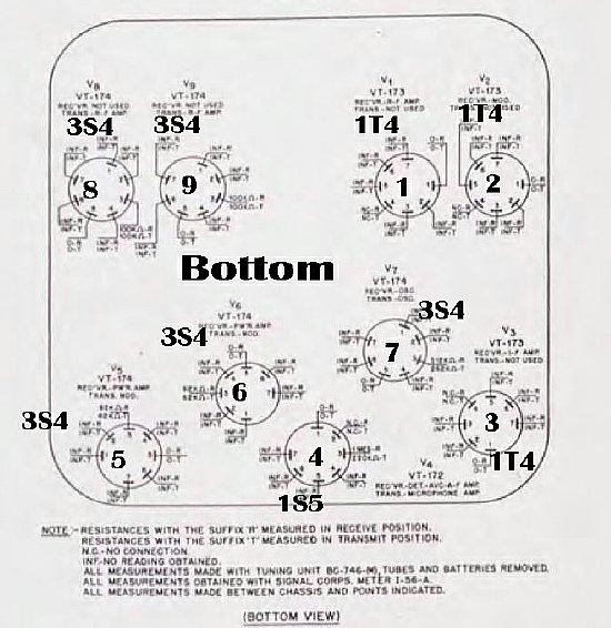
Tube
chart and location Bottom View.
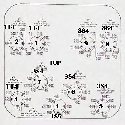
Tube top view. (I flipped it)
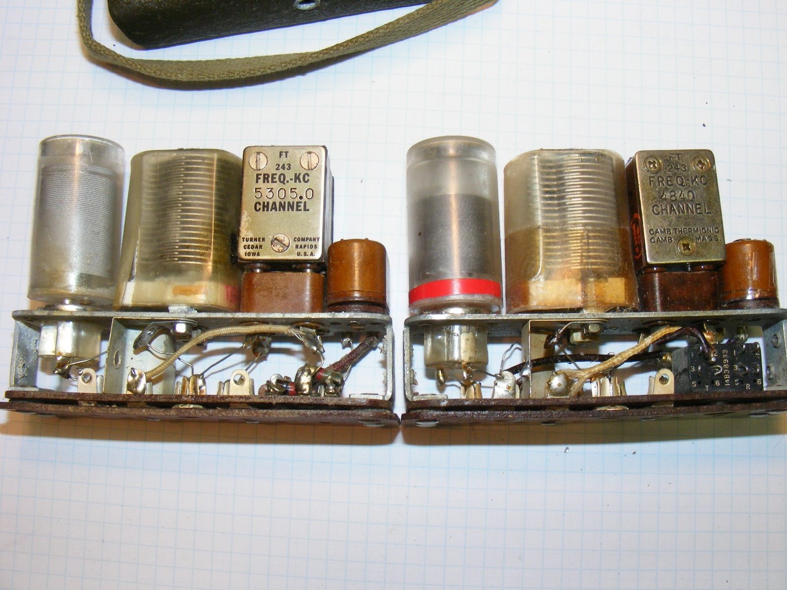
A
vs. B tuning units. Note that the B unit has a provision for multiple
taps which are easily changed to vary the bias .On the A unit fixed resistors
are soldered in place with a tap.
Q.
Can you use an A tuning unit on a B RF unit?
Ans: Yes but expect transmit currents to
be slightly higher and slight loss of modulation(approx 15 percent) due
to bias differences. But overall perfectly useable. An A unit
can be easily rewired to copy a B unit.
WARNING: Do not transmit without a functioning tuning
unit installed and providing bias as excessive plate and screen currents
will occur. On one of my units the current increased during transmit
from 60 to 105 ma. Receive current went from 6 to 16.
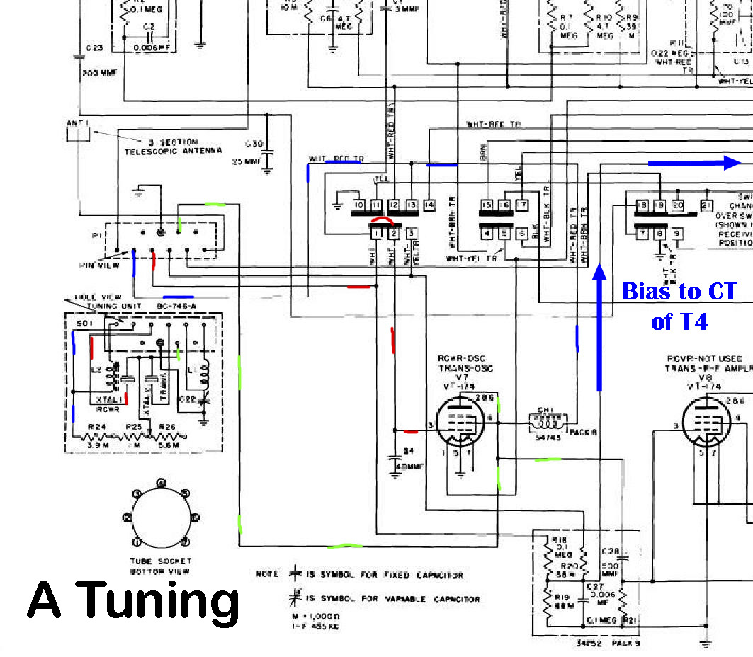
Click to enlarge
The "A" bias unit utilizes 3 fixed resistors and tap.
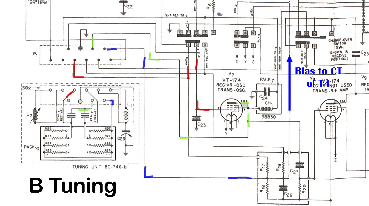
Click
The "B" bias is provided by a 4 resistor network for transmit and receive. The units that I examined did not have a receive tap installed.
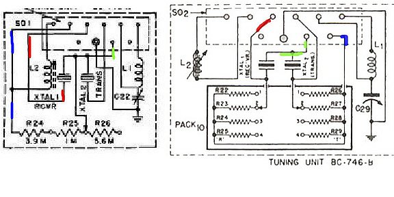
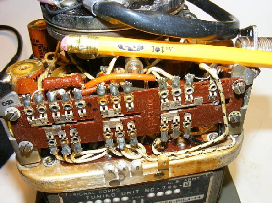
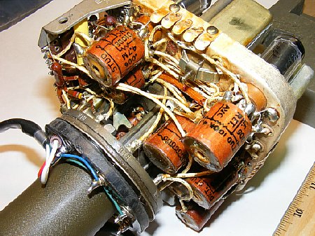
A
and B for comparison. Receive crystals are on the left and transmit crystals
are on the right. Note that 3.9 "M" on the left is 3.9K, 1 "M"
is 1K etc.
The right unit values
for transmit were R26 -15K, R27- 60K, R28- 150K and R29 -330K.
Most of the B tuning units I examined were tapped on Transmit only at
position number 3 on R-28 which has a value of 150K. Operation on 75-80
meters you can convert an A unit to a B can be done by removing the resistor
network on A and installing a single 150K resistor for the Transmit tap.
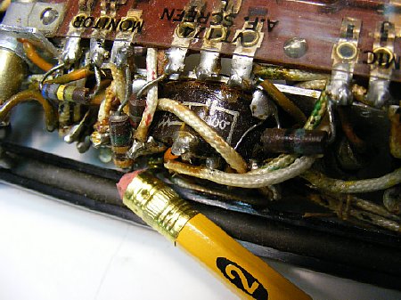
B unit network with transmit tap at position 3. Taps are moved according to frequency and perhaps activity of the crystal. Several B tuning units were examined all units had a transmit tap but the receive tap was not used. I played with the tap while transmitting on 75 meters and noticed when going from tap 3 to tap 2 the total transmit current reduced by a couple of mills and the modulation increased a small amount but moving the tap through all the positions did not produce any major event event with the tap disconnected.
"A" tuning unit resistor network. The tap soldered in place.

Click
to enlarge.
BC-745 BC-611F size Comparison. Both units were manufactured by Galvin.
The BC-745 used the capacitor- resistors "packs" extensively. The ones installed on the BC-745 are larger and have easy to read diagrams printed on the exterior.
The BC-611 A through model E used the same "pack" system.
Click
The BC-745 had a tube count of 9, the set has better audio stages and more RF and audio output. RF output was .75 watts Vs the BC-611 of .38 watts, barely enough to wiggle your S meter or about 3 dB which is half an S unit.
The BC-611 utilized 4 tubes.
The BC-745 could rapidly change frequency in field using plug in tuning units. A total of 27 channels were available. The BC-611 could not change in field and required realignment each time the frequency was changed. A total of 50 standard frequencies were available for the BC-611. Note: The BC-745 did not issue a tuning unit for 3.885 as standard equipment.
The
BC-611 and BC-747 coils are of similiar construction but
are not designed to be innerchangeable.
The Large Antenna coils were of the
same construction but frequency ranges used different inductance values.
In general the bC-611 Antenna coils had a much higher inductance for a
given frequency range.
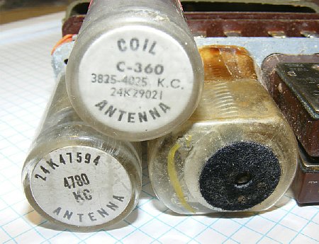
Q. Can a BC-745 use the BC-611 Antenna Coil C-360 (3824-4025 kc) on 3.885?
A,
NO. The BC-611 Coil C-360 has too much inductance (approximately
80-85 uH) for use with the Pogo Stick transmitter and its 95 inch whip
antenna. The BC-611 coil of 80-85 uH was designed to load the shorter
41 inch BC-611 antenna. Approximatgely 54 uH inductance is needed for
the Antenna Coil on the Pogo Stick. Try using BC-611 coils marked for
4625-4825 or try coils marked in the 4800 4900 range.
Q. Was a 3885
Channel Tuning unit made for the Pogo Stick BC-745?
A. No but the 3825 coil set (Ch 2) will be close enough for government work. You will probably have to remove a few turns on the receiver tank coil (reduce inductance) for 3885 operation - shown below.
WARNING: Use of a BC-611 coil C-360 (3825-4025) on the Pogo Stick frequency of 3.885 will result in a out of resonance condtions for the final tank transmitting circuit. You will not be able to peak the transmitter on Field Strength or peak the receiver on noise. Continued operation with this out of resonance condtion may result in the lost of final tubes 3S4 tubes (2) due to higher than normal plate currents. In addtional modulation will be distorted.
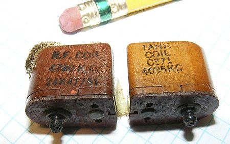
Left
Pogo Coil Right BC-611 Coil
The
receiver tank coils for both sets are of the same construction but slightly
different inductance and tuning ranges. The receiver tank circuit has
a bandwidth of approx. 200 kc. When tuning a definite peak of 2 to 3 turns
should occur. The target inductance for 3.885 kc is 24 uH
which will allow a nice 2 to 3 turn peak with the slug in the middle of
the tuning range.
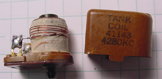
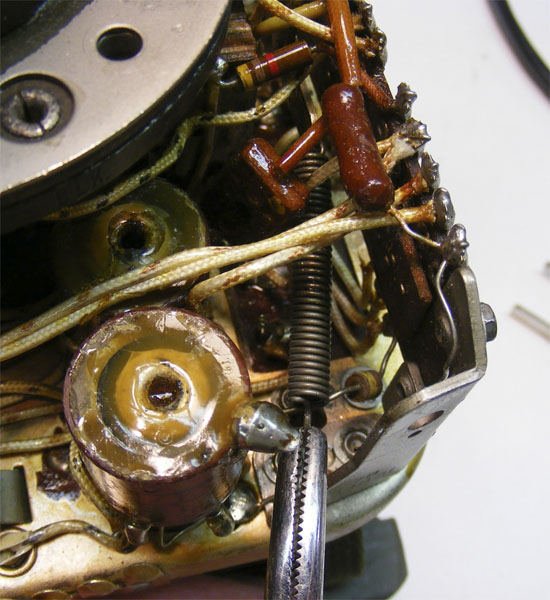
The receiver "tank" coil is easily modified. Adding turns to a 4280 coil brought it down to 75 meters. Approximate inductance needed is 24 uH.
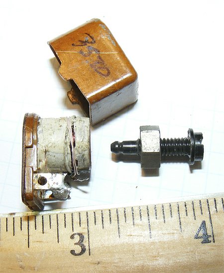
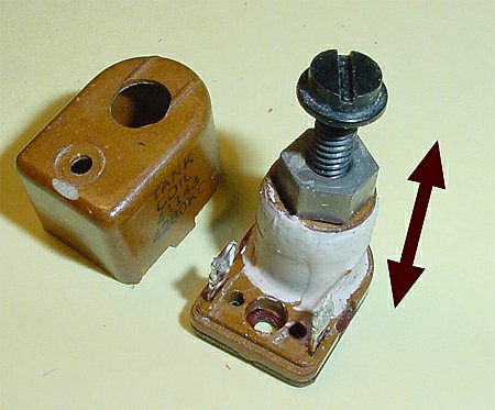
The coil adjustment screw has a 8 Turn range. A pretty robust coil but do not force the adjustment past the stops. The plastic adjustment screw moves a small piece of ferrite core up and down inside the coil.
8 Turns gives a tuning range of approximately 5 uH.
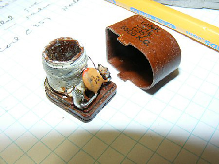
A BC-611 coil C357 was modified for use on the Pogo frequency 3.885. A 47 pF fixed capicator was soldered across the terminals.
A special note: Robert Downs WA5CAB has a nice selection of coils for the BC-611. He is an excellent source for military radio parts and has helped hundreds of military radio and vehicle collectors.
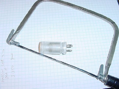
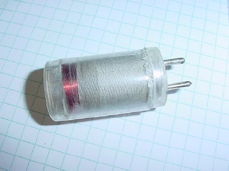
The antenna coil can be opened for modification. Carefully saw through the outer cover near the base and remove.
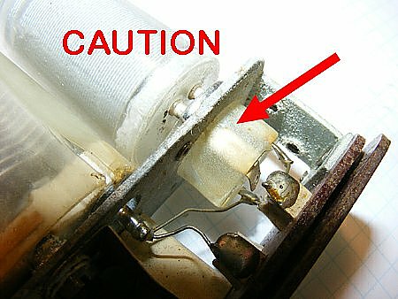
Use caution when removing the antenna coil as the socket and coil pins are fragile.
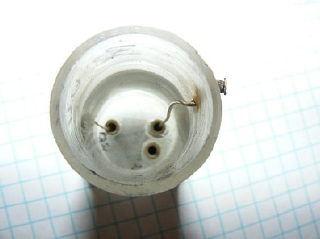
Take the top winding and unsolder and remove it from the pin and pull it outside of the coil form. . Then insert a solid piece of wire into the pin and solder.
Feed the new solid piece of wire through the coil form and make a tab. This tab will become an anchor point for your coil modifications and RF trails. Easy to solder and unsolder.
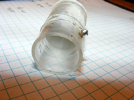
Add
turns to bring the selected coil down to 75-80 meters. On 3885 approx
55 uH is required. When the turns have been added make the connection
inside the form and slide the cover back on and glue.
A BC-611 coil C368 (5.500kc) was modified with 20Turns of #36 and worked OK on 3885 and measured 56uH. This allowed the variable antenna capicator to be in the middle of its travel.
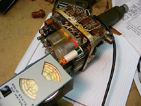
A dip meter can be used. My modified 3885 coils dip around 3.8 with confirmation of the dip meter frequency using a near by receiver. Expect coverage of about 200kcs across the 80 meter band with a 55 Uh coil while tuning C22 in the tuning unit from minimum to maximum capacity. It is best to connect a 94 inch wire antenna while dipping your coils for best accuracy.
Continued
on Page 2
Return
to K4CHE Index