
PRC-10 Ops and Maintenance Tips (Part
1)

These pages contain information on: (click for navigation)
a.
Alignment tool fabrication.
b.
Receiver Transmitter case power rewire.
c.
Antenna Circuit Discussion.
d.
Antenna Notes (tape, fish pole)
d.
Antenna insulator mount info. (It does not have a switch)
e.
Antenna connector resistance and RF checks.
And I apologize in advance
as to the order subjects are presented on this page its just the way events
happened here on the bench. Section 2 will have further details on powering
the PRC-10 , tube info, alignment, and trouble shooting as well as a operating
tip or two that have not been published. k4che
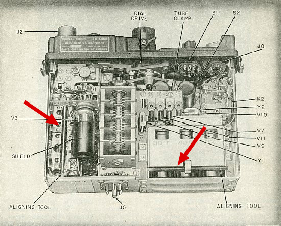
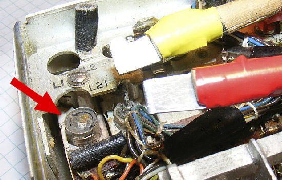
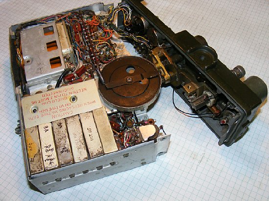
Arrows
point to the alignment tools in their mounts (2).
First
problem. No Alignment tools. In all the years that I have been working
on the PRC-8,9, and 10 sets I have never been lucky enough to come across
the alignment tools. My theory is that during overhaul at Depot they removed
them to keep the GIs from tuning up the radios. My other theory is that
aliens came down and requisitioned all the tools for experiments. Fair
Radio says they have not seen the tools for a very long time.
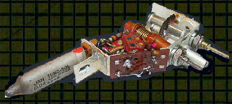
A simple tool can be fabricated for the large powered iron slugs used in the inductor coils in the AFC and Mixer modules. The improvised tools end blades shown above were fabricated from a small plastic strip cut from a pill bottle and a pieces of scrap aluminum. The plastic blade was my favorite as it causes less damage to the slug. The plastic was measured at .045 inch thick and inserted into the end of a wooden dowel. Be careful when tuning - the slugs are fragile.
The AFC tuning is critical and directly effects transmit frequency and will be discussed in more detail below in the alignment Tips section.
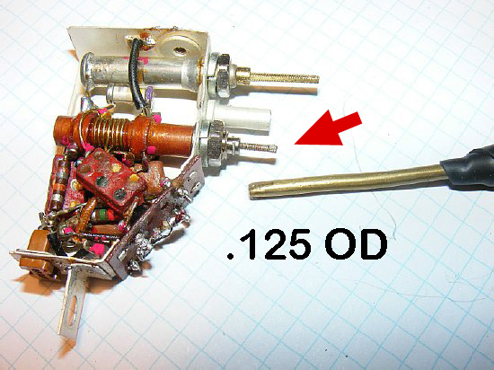
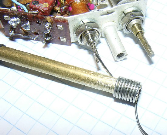
The inductors in the other modules with the small adjustment shafts require a simple tool fabricated from .125 outer diameter brass tubing. Just crimp the end. An older ball point pin contains this tubing or visit your local hobby or crafts shop.
"Improvise-Adapt-Overcome"
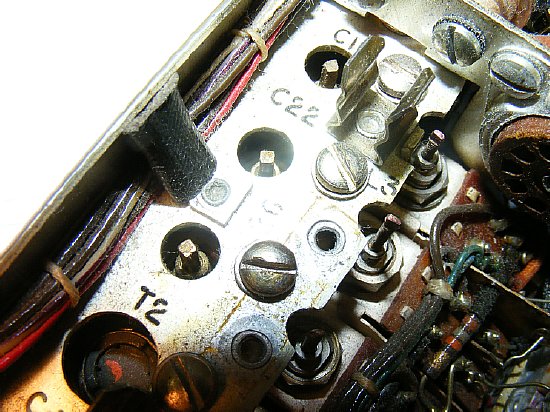
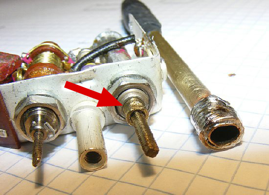
The trimmer capacitor adjustments for the modules are recessed and are not easily adjustable. A lot of Hams have tried to turn the square threaded shaft - which doesn't work and can damage the piston capacitor. A special tool is needed for adjustment of these recessed caps and is discussed below.
The trimmer capacities have a threaded shaft and unfortunately these caps require a special tool in order to make adjustments. Most piston type capacities in modern equipment have a screw driver adjustment (shown on the right) but in the case of most of the modules in the PRC-10 the special tool is required to turn the adjustment on top of the capacitor housing which then moves the threaded shaft up and down. Details of a fabricated tool will be shown below.
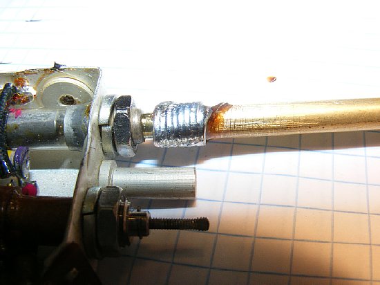
A alignment tool for the piston trimmers can be fabricated from 3/16 OD brass tubing. The type that I used had a .014 wall thickness. Go to a hobby store.
The brass tubing is going to be crimped in order to fit over the "flat" portion of the tuning shaft of the capacitor. But first strengthen the brass tubing wall by wrapping some wire around the tube.
A standard tubing cutter works fine on the smaller brass tubing. Other wise score it with a sharp knife and snap apart.
Strengthen
the outer wall of the 3/16 OD tubing with some solid wire and then solder.Wrap
the wire first and then solder.
Don't
crimp the tube until you have reinforced it.
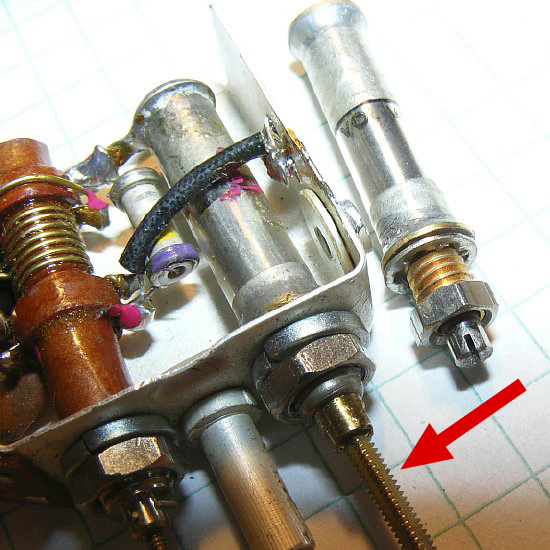
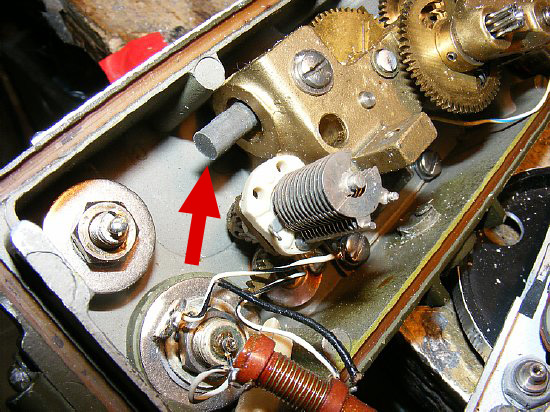
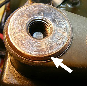
The
end of the reinforced tubing is crimped slightly to fit over the flat
sides (2) of the trimmer adjustment. The arrow points to one of the flat
sides.
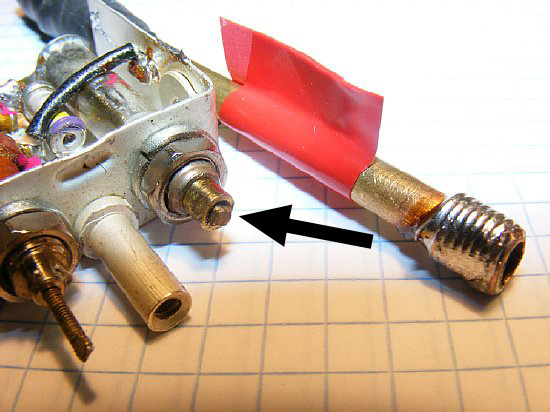
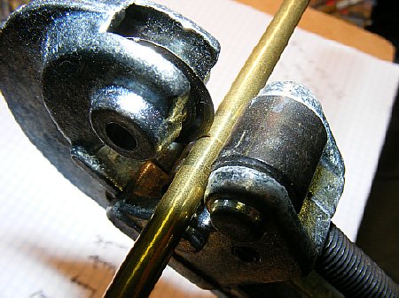
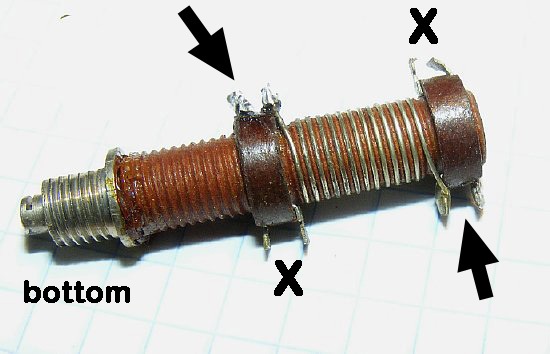
Trimmer capacitor at maximum
In the photo above the trimmer
capacitor has been adjusted for MAXIMUM capacity and the threaded shaft
has all most disappeared into the adjustment head. Turning the adjustment
CCW results in a increase of the capacitance and the threaded shaft will
become shorter in length as it enters the adjustment housing and pushes
the interior piston into the housing. CCW reduces the capacitance and
the threaded shaft grows longer as it extends out of the housing.
TIP: The trimmers have a 28 to 30 turn adjustment. Put a flag on your tool and keep track of the turns - - don't just ham it and turn to see what happens, keep track of the turns in case you have to return to the original setting. Red tape works good but yellow or blue will suffice.
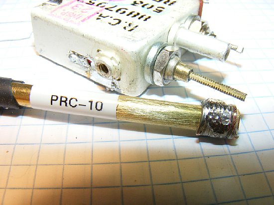
Finished and ready for the alignment procedures.
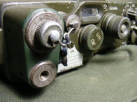
Remove the connector cover and inspect wiring. Rewire if necessary. This will prevent melt down of your battery pack or inverter power supply.

The wring harness is longer than original for ease in plugging in power supplies and for bench adjustment.
During rewire of the receiver transmitter enlosure it is easier to completely remove the connector. Clean the contacts and then rewire. After wiring fish the wires through the bottom of the RT box and then wire the male connector.
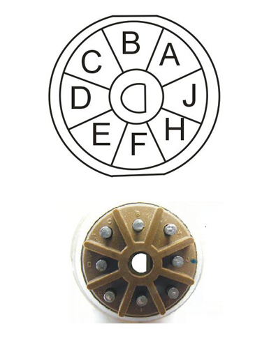
RT connector.
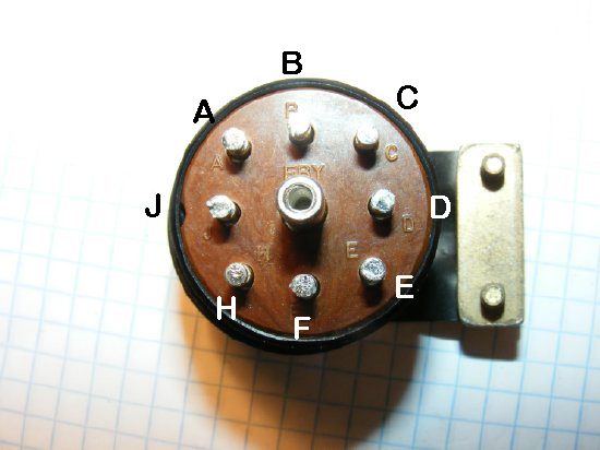
When wiring the male connector don't forget to feed the wire through the clamp and outer shell.
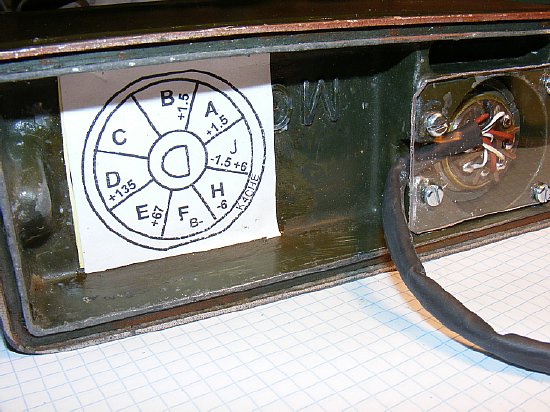
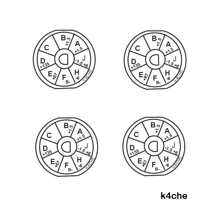
The connector chart comes in handy during rewire and trouble shooting. Note the clear lexan cover on the connector which was fabricated as the original cover was missing on my $5 hamfest purchase. The new wiring is enclosed in a section of heat shrink tubing.
CLICK
to enlarge
Click
to enlarge for full size for printing. Note that the voltages are printed
for each connection to aid in trouble shooting.
Most of the PRC-10s that have purchased at ham fests have been "ham hacked" and in the process the front control panel was removed and then replaced. During this ham hack process wiring errors are usually made on the antenna loading coils during the reassembly. This is usually the result of not disconnecting the wiring of Long Antenna loading oil L6 prior to removing the front control panel. If in doubt RTFM. L6 is mounted on the main chassis- - more info below.

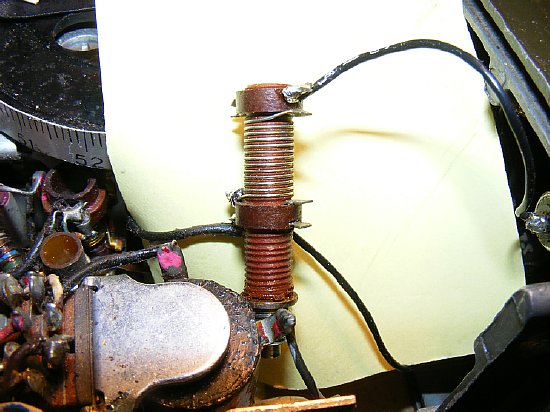
Unsolder wiring from the top and bottom of the long antenna loading coil L6 prior to removing the front control panel. The large object to the left is the main RT relay K1. L9 and adjustable coil is the final XMTR OSC plate coil and has terminals at the top right for the center tap and a wire runs between this top connection and the bottom of L6. This connection is often wired wrong. Don't screw this connection up.
L6 Loading coil.
PLEASE NOTE: L6 has several soldering terminals- Be sure and solder to a active terminal that is connected to the winding of the coil.
The bottom of L6 is connected to the top of L9 which feeds a center tap.
CLICK to enlarge
L9 is the final tank coil for the transmitter. During transmitter alignment L9 is adjusted for maximum power into a 50 ohm load. The L9 center tap circuit feeds the loading coils for the Short and Long antennas. On most of the ham hacked PRC-10s you will find that L9 tuning screw has been tuned to near destruction.
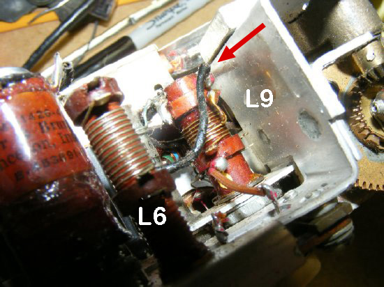
Another
view - - the black wire runs from the top terminal of L9 (side
nearest the chassis bracket) to the bottom terminal of L6 the loading
coil for the long antenna.
When wiring or disconnecting L6 its easier to just remove the mounting nut and free the coil from the chassis.
CLICK to enlarge
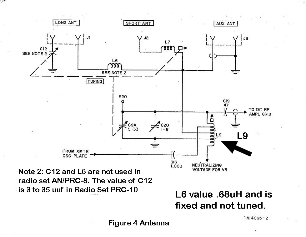
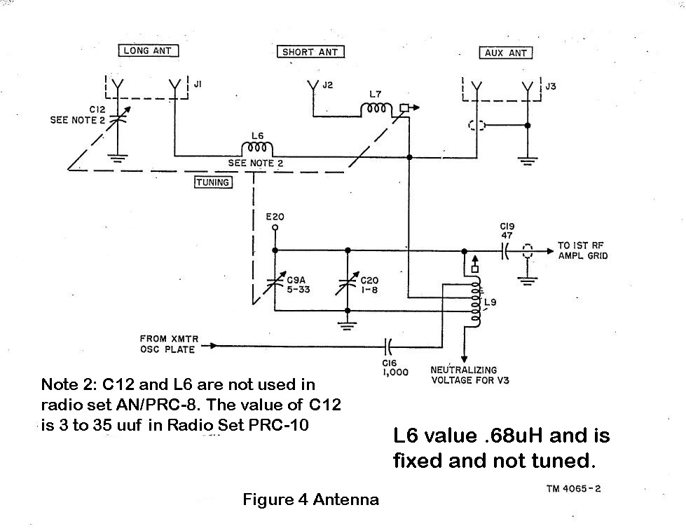
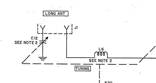
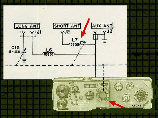
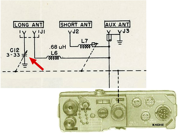
The PRC-10 antenna system is unique and is designed for multiple antennas. Note that the Short Antenna loading coil L7 inductance varies with the tuning (dashed line) using a ferrite slug. When the set is tuned to a lower frequency the inductance increases as the slug enters the coil and at a higher frequency the inductance decreases as the slug is retracted from the coil. L7 is only used with the Short Ant. A Variable Capacitor C12 for the Long Antenna loading also varies with tuning (dashed line) and will adjust to full capacitance at the lower frequency and minimum capacitance at the higher frequency. C12 is only used for the Long Antenna. L9 is adjusted for maximum output during alignment and provides approximately a 50 ohm output and feeds the loading coils L6 and L7.
NOTE: A lot of useful information is available in the manuals for the PRC-10A- If your set is a PRC-10 then take time to go through the 10A manual.
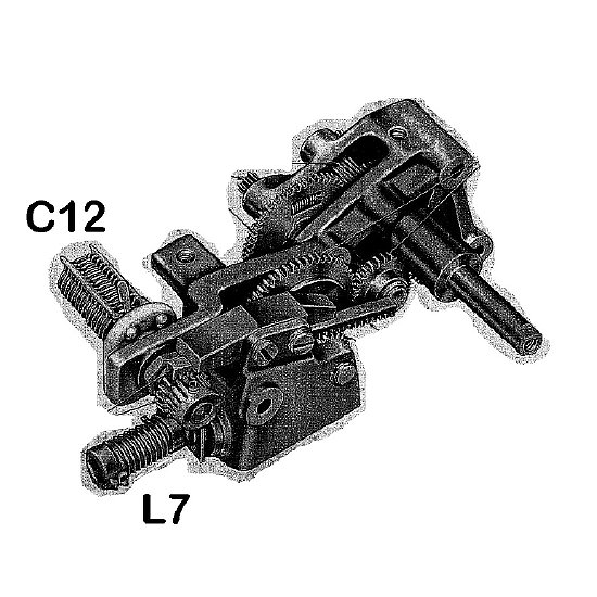
L7 the Short Ant loading coil and C12 the Long Antenna loading capacitor are both tuned via a complex series of gears. The variable capacitor C12 is only used on the Long Antenna. L7 is only used on the short Tape antenna.
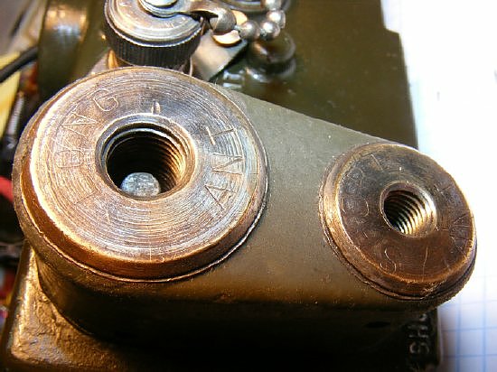
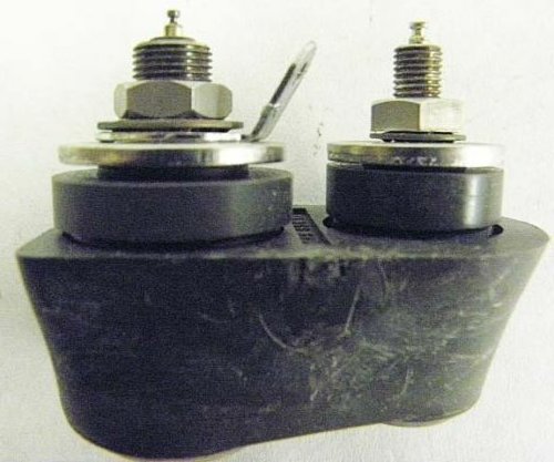
Two separate threaded antenna mounts are mounted on a insulated base. A separate BNC connector is also available for 50 ohm output.
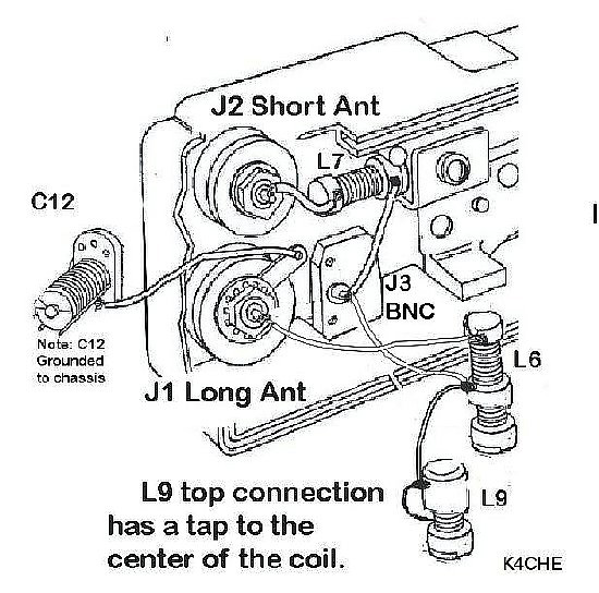
PRC-10 front control antenna connector wiring. C12 has been moved out of the way for illustration. C12 is always connected to the outer threaded section of the Long Ant J1. There are no switches that are activated when the Long Ant is inserted as C12 is always connected.
The T.O is a little shy on "practical wiring" diagrams so use the above chart.
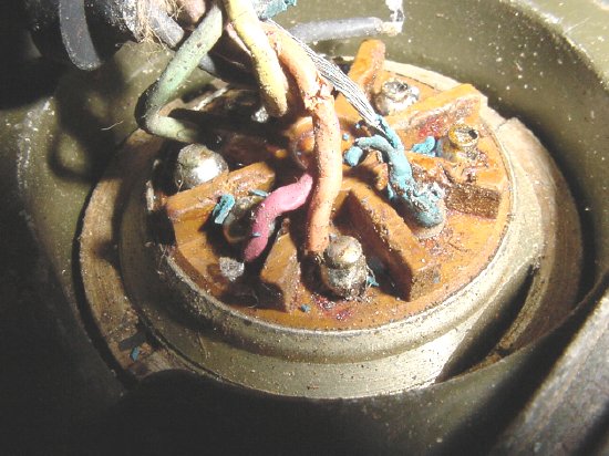
On this ham fest set the short antenna loading coil L7 is missing. Note the broken L6 coil (bottom) that is not attached to the chassis and was left dangling on its own during a ham hack process. If all else fails RTFM.
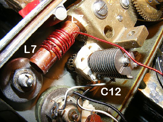
For
some reason the Short Antenna coil L7 is MIA on several of the
sets that I've worked on. A simple fix is to just wind a new coil. The
value of L7 when the slug is at minimum is .4uH. If the L7
coil is missing and you do not want to fabricate another then cab try
bypassing the wiring and wire the Short Antenna connection direct to the
BNC center pin. Then the BNC center pin should be connected to the bottom
of L6 - you will not have proper loading but for short distances
it will work. A practical wiring diagram can be seen by scrolling back
a couple of photos.
Long
Antenna connector. The lug connects to C12.
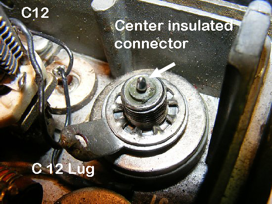
Long
Antenna J1 connection. The center connection is insulated from
the outer metal shell. The large lug is attached to the threaded portion
which is part of the outer metal shell of the mount. The large lug connects
to C12 which goes to ground. There is a insulated section underneath
the large lug and lock washer which keeps the threaded portion of the
mount above ground. The center insulated connection is connected to
a spring loaded contact inside the connector. See next photo. There are
no switches.
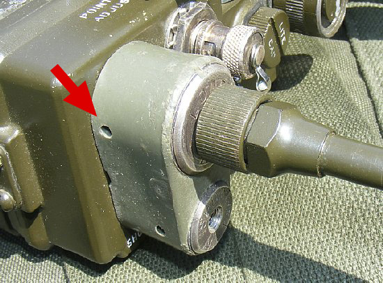
The
large threaded shell (LONG ANT) is insulated from the chassis by the large
plastic insulator and then by thick insulated washers underneath the chassis.
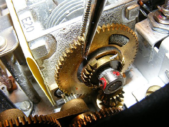
TIP: The 3 section gang capacitor gear is split and spring loaded. During reassembly of the front control panel you have to split the sections in order to provide a load on the tuning shaft. A surgical clamp comes in handy to hold the split gears during reassembly or you can fabricate the "spring clip" as described in the manual.
Everything you wanted to know or didn't want to know about the PRC-10 antenna mount.
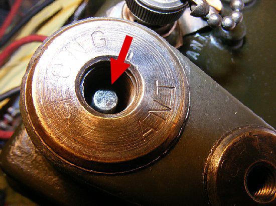
This
center contact does not activate a switch.
Note the small round center connection inside the Long Ant mount. The
spring loaded contact compresses down into the mount as the antenna base
is screwed in to make positive contact with the bottom connection which
is connected to coil L6. This spring loaded point contact is connected
to the center connection of the mount - - The metal threaded outer shell
of the mount is insulated from the chassis and is connected underneath
by the large lug to C12 at all times. When the antenna is screwed
all the way in it makes contact with the center point and at the same
time connects to the threaded shell which is always connected to C12. Note:
It is possible to insert the Long Antenna and not screw the base it all
the way in resulting in a bad connection to the center pin. Then you are
SOOL.
LONG ANT J1 threaded mount fixture and center contact pin. No Switches.
Long antenna spring loaded center contact shown above. When the antenna is inserted into the mount the it makes contact with the center spring loaded tab and compresses for positive contact. The antenna base musts be firmly screwed in so as to fully depress the spring loaded contact otherwise intermittent operation will result. The center contact at the bottom is connected to the L6 loading coil. The outer metal shell that holds the threaded base of the antenna is always connected to variable capacitor C12. No switches to activate.
C12 is always connected to the insulated outer metal base section that is the threaded portion of the mount. J1 is the center spring loaded contact and is always connected to the loading coil L6. No switches. When the base of the Fish Pole antenna is inserted into J1 it makes contact with L6 and C12.
As the threaded section of the "adapter bushing" of the Fish Pole antenna is screwed into the mount it makes contact with the center spring loaded contact and at the same time the threads of the antenna adapter bushing make contact with C12. No switches involved. A simple elegant design. The only flaw is that if the variable capacitor C12 becomes corroded or shorted then RF is shunted to ground
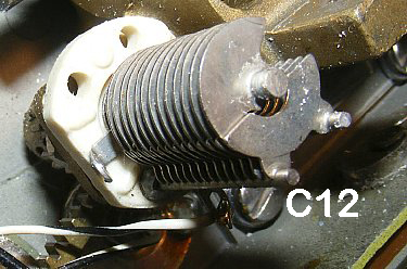
Check C12 for corrosion or shorted plates.
Long Ant Short Ant
Side view of the antenna base. Everything is insulated from the radio chassis. The center pin inside the Long Antenna section is insulated. The Short Antenna center pin is not insulated from the metal threaded portion- it is all one piece.
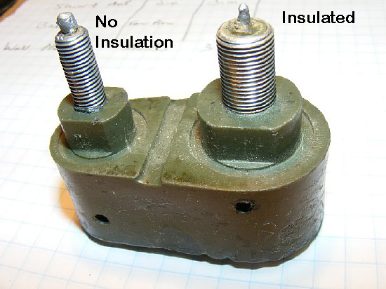
The center pin connection of the Long Antenna is insulated from the metal threaded portion of the mount. The Short Antenna mount is all one piece and the center is not insulated from the threaded portion. The PRC-10 mount is sealed and can not be taken apart. There are no switches.
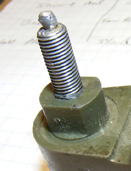
The Short Antenna mount is all one piece and the center is not insulated. Insulated washers are used when mounting to the chassis.
Drain holes for moisture. There were no antenna mount covers or protectors. Later the PRC-10A had a mount insert cover for the Long Antenna.
PRC-10A
Long Antenna had a cover for the Long Antenna mount.
Q. Why
is a cover needed for the Long Antenna and not for the short antenna?
Ans. In the event water or moisture entered the long antenna mount it could possible connect C12 to the center pin and upset tuning of all of the antenna ports. Water entering the short antenna mount does not hurt anything. Confused yet?
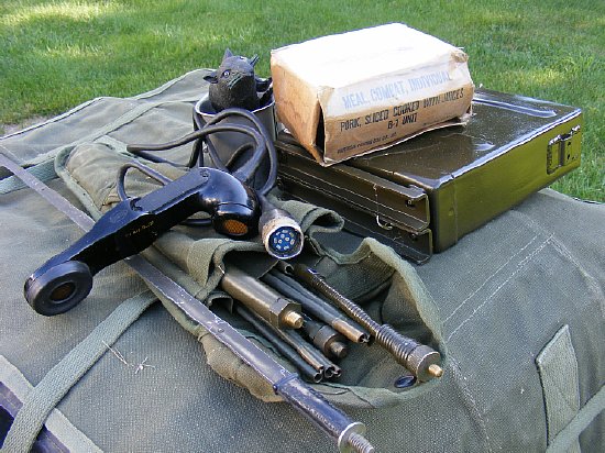
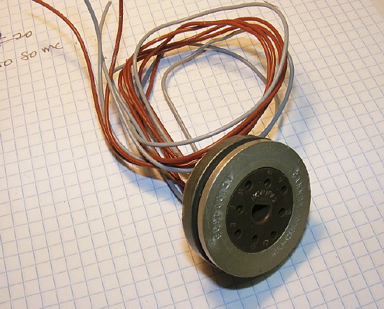
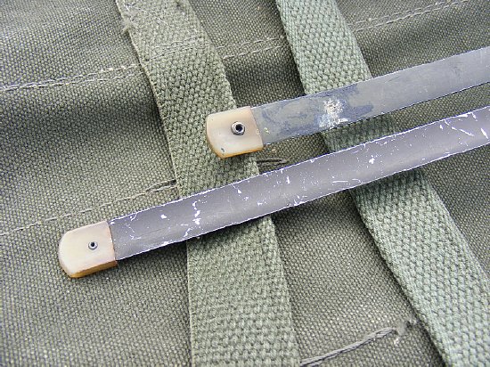
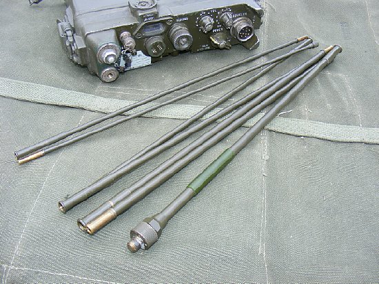
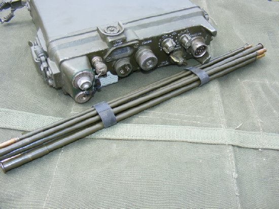
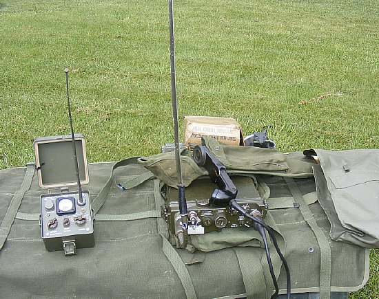
This
CW-216/PR bag contains most of the antennas for the PRC-10 as well as
a H-33 handset. Note: The early H-33 used with the PRC-10 has a "straight"
cord. The tape antenna and "gooseneck base" comprise the AT-272/PRC.
The fish pole antenna and a AB-129/PR spring section can be used for increased
gain. Both antennas will be discussed below.

Click to enlarge
The PRC-10 utilized the H-33B handset with the straight cord.
The gooseneck base and tape antenna allows mounting the radio at any angle positioning the antenna for best reception.
The 29 inch Tape antenna is tuned by L7 a variable inductor that varies with the main tuning knob.
No value was published for L7 on early schematics but later the PRC-10A schematics listed L7 as .4 uH.
Click
to enlarge. N6GCE
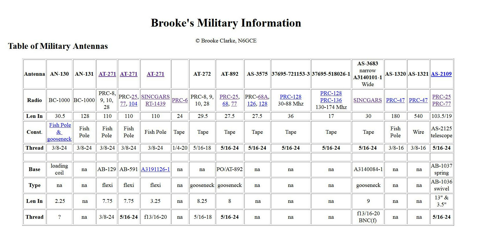
The
PRC-10 antenna base sections are a different thread size than antennas
used on later model radios such as the PRC-25. Brook Clarke N6GCE has
an excellent antenna chart on his "Tape Whip Adapter" page.
The chart is a wonderful contribution to military radio collector.
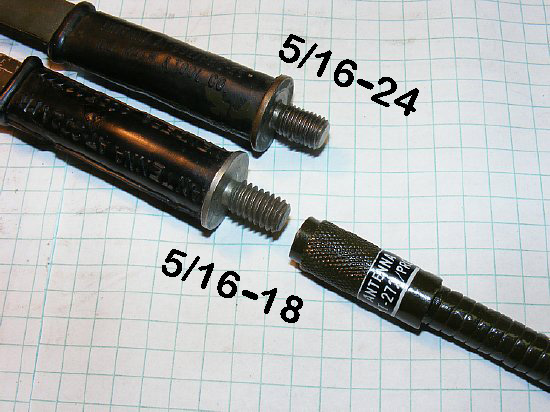
The PRC-10 tape antenna AT-272 is comprised of the tape and "gooseneck" base. The tape antenna threads of 5/16-18 are slightly different than later model equipment tape antennas such as the AT-892 (PRC-25, PRC-77) which utilize a 5/16 -24 thread.
The
PRC-10 tape antenna (AT-272) is approximate 2 inches longer than the later
model tape antennas such as the AT-892 or AS-3575.
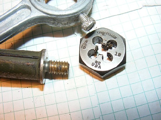
An
emergency antenna for the PRC-10 spring base can be fashioned from a later
model tape antenna such as the AT-892 or AS-3575 by simply use a 5/16-18
die and change the threads.
Improvise-Adapt-Overcome
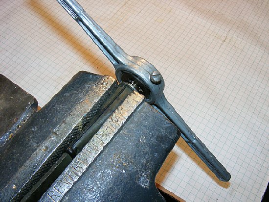
Use a vice to hold the AT-892 and change the threads. Simple project.
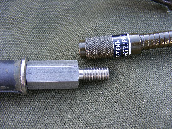
Another
solution for the later model AT-892 tape antenna thread problem is to
use a Thread Adapter to convert the 5/16-24 to 5/16-18 threads.
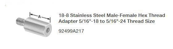
McMaster- Carr part number 92499A217
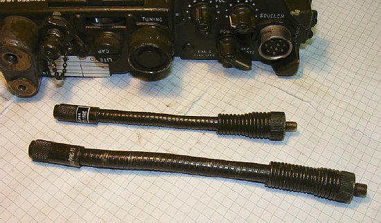
The shorter AT-272 gooseneck as compared to the PRC-25 AT-892 gooseneck. Unfortunately the PRC-25 gooseneck has different threads and will not work on the PRC-10. so-sorrie G.I. No workee
The
AT-272 "fish pole" antenna.
TIP: Use rubber bands cut from a section of a bicycle inner tube to hold the Fish Pole antenna sections together during storage.
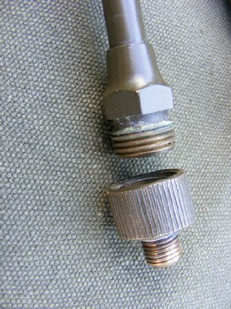
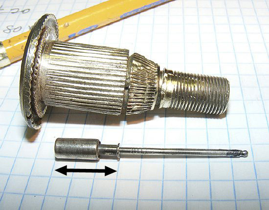
Fish
Pole threaded base (removable)
Q. Why
is the threaded base (adapter bushing) removable?
Ans: "That's a good question. I had thought for many years that it was an adapter to adapt the AN-131 and AN-131-A to the BC-1000. But years of digging up miscellaneous information (i.e., my database) has finally convinced me that there is no earlier set that used the AN-131. Studying TM 11-242 and the parts list therein doesn't actually spell it out, but I have come to the conclusion that the only thing that the 5/8"-18 thread on the bottom of the bottom section of AN-131-A fits is the adapter bushing. Which finally leads to the obvious (at least in hindsight) conclusion that it is an assembly part - removed only for maintenance (to replace either the spring and cable assembly or one of the antenna sections."
"So the short answer is that it's removable so that you can repair the antenna with (assuming that you have access to the Army supply system for repair parts)."
Robert Downs - Houston WA5CAB dot com (Web Store) MVPA 9480
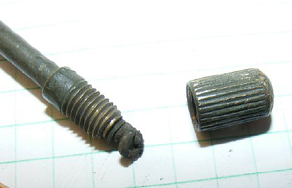
The Fish Pole AT-271 antenna tip can be removed for knot access.
Take the knot loose and you will have several small fishing poles.
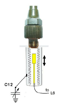
The Long Ant is tuned by C12 which varies as the main tuning is varied. At 51.0 the variable capacitor is at minimum and as you tune lower in frequency the capacitance increases. The good news is that at 51.0 if the plates are corroded they may not short out as the plates or at minimum.
Possible Modification? Change L6 to a variable inductor and tune for maximum field strength at 51.0 Mc. Early schematics indicated that L6 could be tuned.
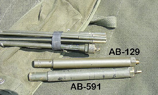
The
PRC-10 AB-129 Antenna Springs Section as compared with the PRC-25 AB-591
section. The AB-591 base thread is 5/16-24 and does not fit the PRC-10
Long Ant mount which requires a 5/16-18 thread.
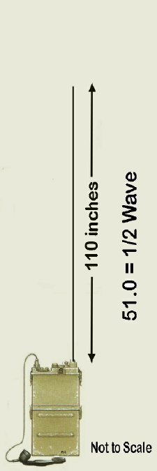

As it works out the Fish Pole Antenna length of 110 inches is a half wave on 51.0 Mcs. Basically you have a "end fed" half wave with the same gain as a half wave doublet. The H-33B handset with the straight cord acts as a counterpoise and its length is more than the 5% of a half wave counter poise usually needed for a end fed half wave.
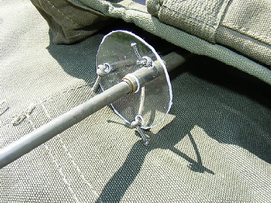
TIP: A simple guy line tie point can be fabricated to provide for attachment of light weight guy lines for the fish pole antenna. This is especially important during solo ops when attempting to break the MRCA PRC-10 distance records held by KD3ZK and K4CHE.
QUICK
Resistance troubleshooting checks. Antenna
Connectors Long, Short, and BNC.
a.
Aux Ant BNC center pin to ground: Less than 1 to 2 ohms depending on the
length of the probe leads. ( The BNC is connected to Xmit Osc Coil L9
which has a tap that is grounded to the chassis.)
b.
Short Ant to ground. Less than 1 to 2 ohms. ( The Short Ant is connected
through L7 series coil to L9)
c.
Long Ant center contact to ground. Less than 1 to 2 ohms. Center contact
either depressed or static you may get intermittent readings if the contact
is not fully and firmly depressed into the housing. (The Long Ant is connected
via L6 to L9. There are no switches.)
d.
Long Ant outer metal casing to chassis ground. No resistance. The threaded
outer metal casing is insulated from chassis ground and is always connected
to variable capacitor C12 which is connected to ground. A low resistance
indicates that the variable is shorted either due to a mechanical problem
or heavy corrosion and any high resistance indicates that the cap may
be dirty. Turn the main tuning knob to check for intermittent resistance
readings. Any resistance is bad news as when using the Long Ant as
some RF will be shunted to ground.
The
ME-61 Field Strength Meter can be used for a quick check to see if a antenna
"Port" is active. However because of the low transmit power
by the PRC-10 you will have to get closer to the antenna than shown in
this photo. Mods are available for the ME-61 to increase range and utility.
The 6 meter mod is great when testing the PRC-10 and tuning the antenna
on the PRC-6, PRC-68 etc.
ME-61 Meter 10 and 6 Meter modification that works with very low power
levels.
http://k4che.com/ME-61
6Mtr Mod/
An even more gain can be obtained by doing additional improvements.
http://k4che.com/ME-61/ME-61.htm
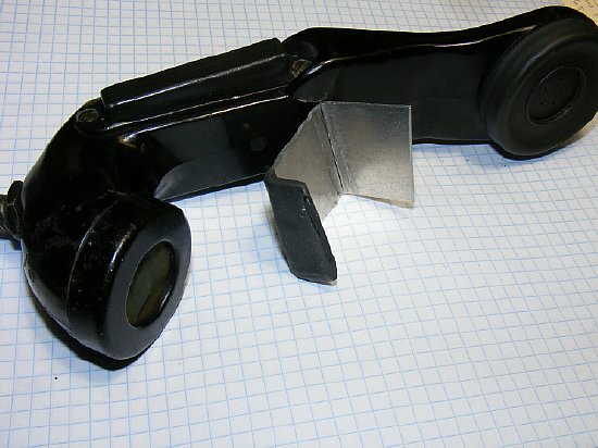
TIP: Make a clamp to hold the PTT when testing.
Ans. Because if anyone has removed the front control panel then the chances are that the antenna wiring is either not correct or is completely missing on one or more of the antenna connectors.
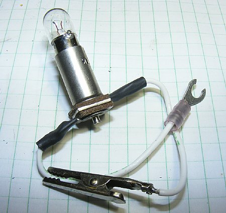
An excellent piece of test equipment - simple and my favorite.
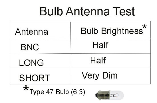
A test light bulb fixture is used to check each antenna port for RF. The manual also discusses use of a light bulb for alignment - see Chapter 5 Transmitter Alignment.
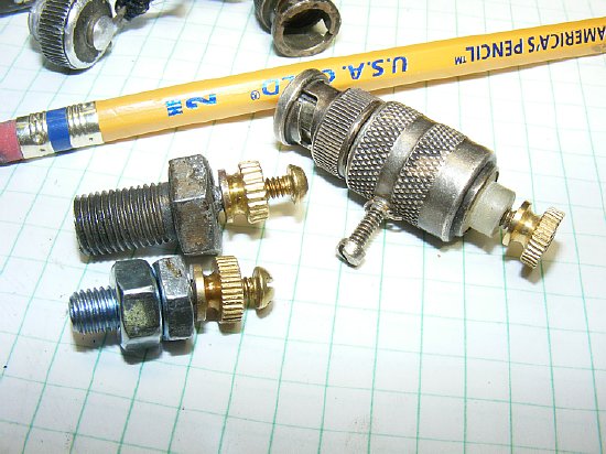
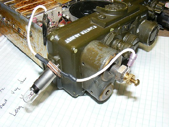
Test fixtures fabricated from 3/8-24 and 5/16-18 bolts. Holes were drilled and brass bolts were soldered in the ends. Knurled nuts were put on before inserting the small bolts into the end and soldering. (I got lazy and did not tap the bolts.) BNC fixtures are available on ePay or at hamfests or just use a short piece of RG-58 cable with the center conductor and shield open and the other end terminated with a BNC.
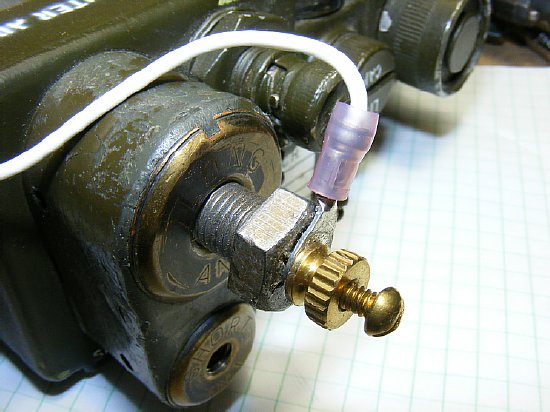
When
inserting the Long Antenna Test Fixture be sure that the bolt goes in
until you feel resistance and then make sure it is tight. Be sure and
remove or at least unscrew this fixture several turns when testing the
Short Antenna - other wise C12 will be connected and upset the
output. Remember the discussion
of C12?
Short
Antenna Test Fixture.
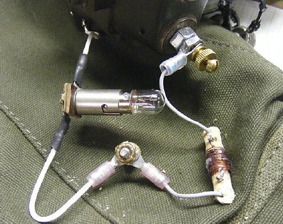
During
your testing if the Short Antenna output is too dim for easy observation
and this perplexing problem keeps you awake at night or you do not like
turning the lights off to view the bulb then the Short Antenna
output bulb indication can be enhance by adding an additional loading
coil in series for matching.
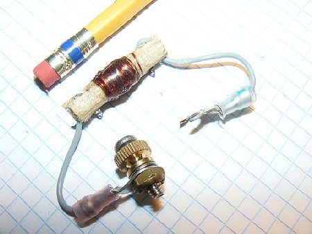
PRC-10
Short Antenna loading coil for bulb test.
1/4
wooden dowel (my favorite coil form). 40 Turns #28 enamel wound in a random
fashion.
Winding is
about a half and inch long. Wire size is not very critical. Target inductance
is 4-5 uH. Try something different wind a coil- light up your bulb.
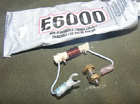
"I
love the smell of E6000 in the morning"
E6000
to hold and protect coil windings. Yes it does effect the Q slightly but
not enough to keep you awake at night. Works good and lasts a long time.
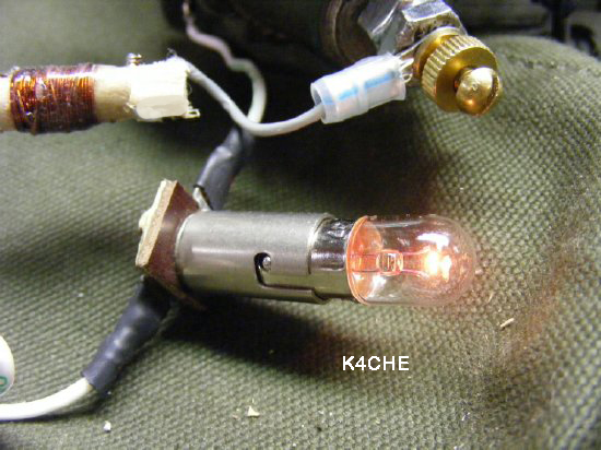
Short
Antenna bulb indication with additional "loading coil" in series
should be about half (1/2) brilliance. DO NOT use the short antenna "test"
loading coil on the other outputs. No Workee.
Improvise
- Adapt - Overcome
Continue with Section 2 Power, Alignment, trouble shooting, operations tips.