
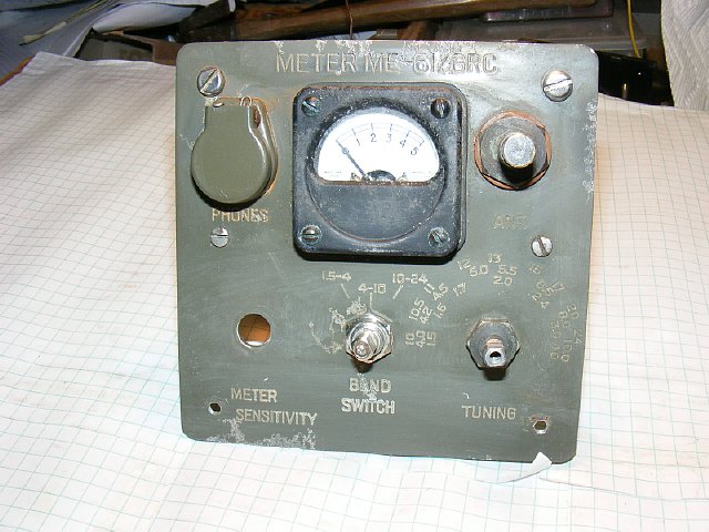
ME-61/GRC Field Strength Meter
Improvements and or build a copy.
The
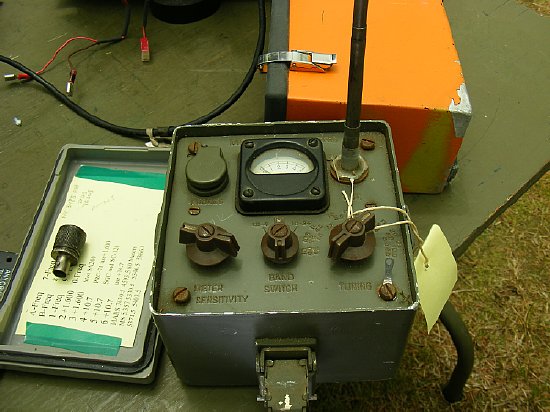
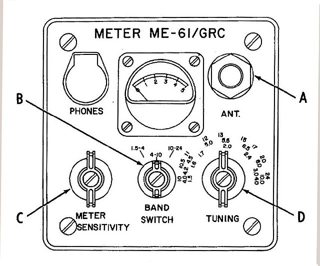
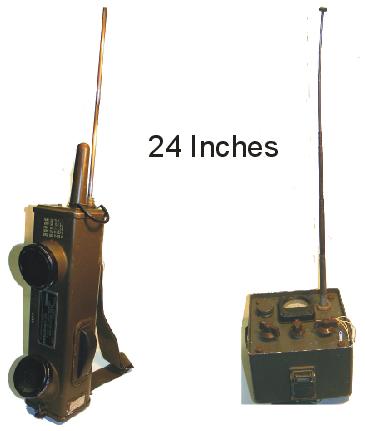
ME-61 Field Strength Meter.
PROBLEM:
The ME-61 was designed for use with higher powered transmitters and has
low sensitivity.
SOLUTION:
A simple Op Amp circuit will increase your sensitivity OR replacing the
1 Ma meter with a 50 or 100 uA meter will also help. More details below.
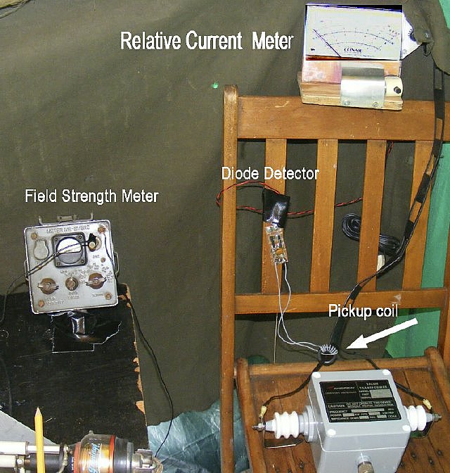
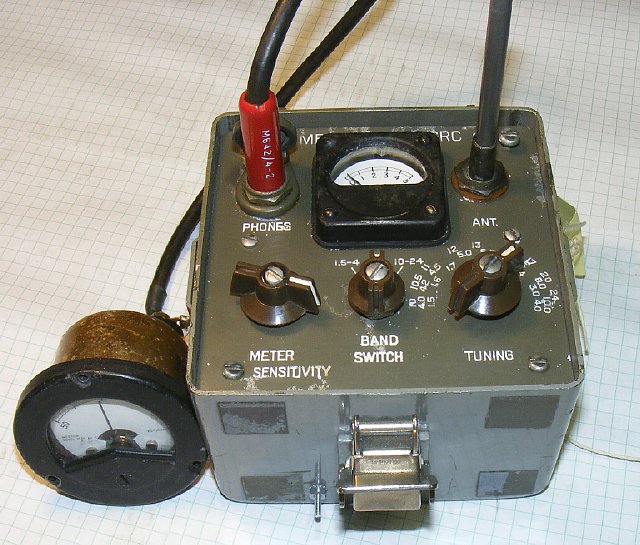
The ME-61 Field Strength meter is invaluable during any king of antenna testing. An external antenna for the ME-61 was used by clipping to the telescoping antenna to increase sensitivity.
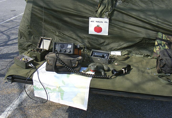
The ME-61 is very handy during portable operations - in the setup above it is used to confirm maximum antenna radiation of a end fed half wave antenna. You can't and should not always trust built in transceiver metering.
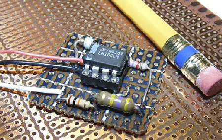
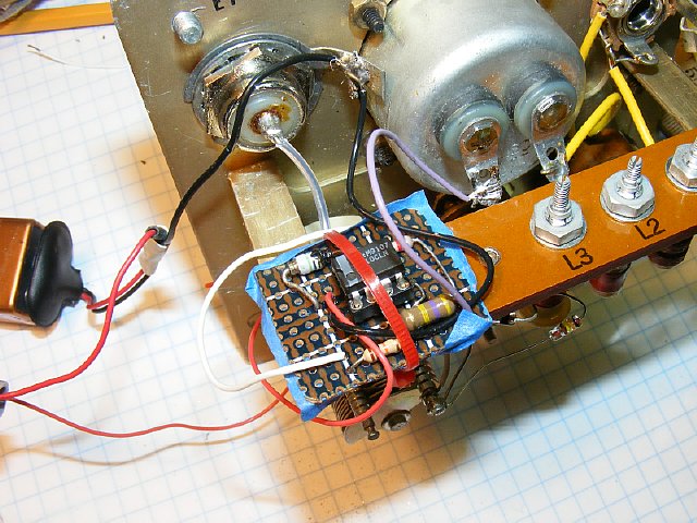
The Op amp circuit on perf board is an easy fit inside the ME-61 case and mounts on the interior RF chassis. The tiny circuit increases sensitivity 30-40 dB and makes the ME-61 more useful. The Op amp board is easy to build. More details below.
NOTE: The ME-61 circuit is easy to duplicate. This setup above was used to evaluate the LM10 op amp. So if you do not have a ME-61 then build this simple circuit and add the Op Amp. More details below.
A simple easy to use design. Frequency coverage is 1.5 to 24 Mcs. Frequency coverage is easily modifiable.
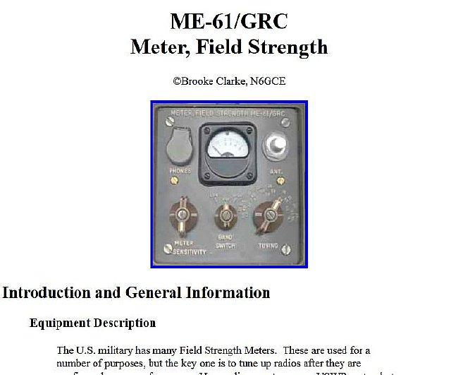
Brooke
Clarke, N6GCE Web Page
Searching
for info on the ME-61 I found Brooke Clarke's page. Reading the "Modification
to improve performance with Lofer beacons in the 160 - 190 kHz frequency
range" by Mitchel Lee I got interested in the LM10 Op Amp.
http://www.prc68.com/I/ME61.shtml
TM
11-6625-682-15 can be found at different sites.
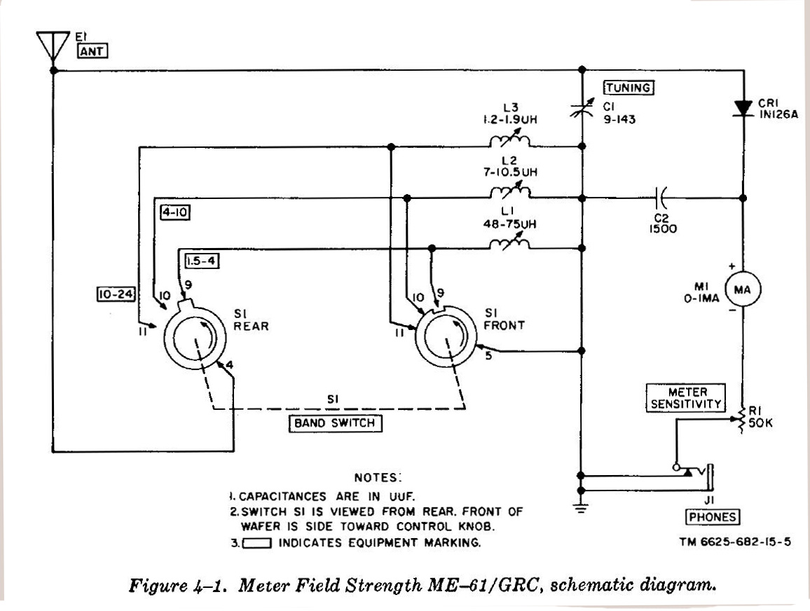
The schematic seems to be a little complicated for a simple meter. The band switch selects one of three band coils and grounds the other two unused coils. A simpler schematic is shown below.
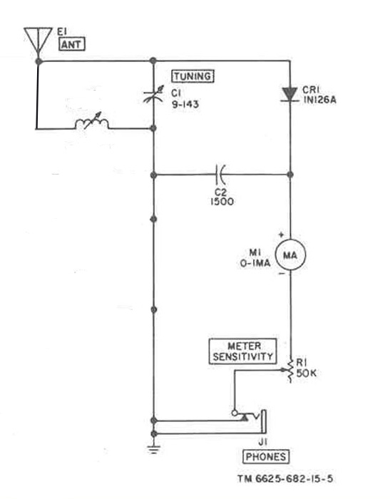
ME-61
simple schematic- only one band is shown.
The
input is a tuned circuit feeding a diode detector which produces a DC
voltage for the 1 Ma meter. Sensitivity is controlled via a 50 K pot.
It is important to note that the pot ground return goes through a leaf
switch on the phone jack.This is a common problem with the ME-61 as the
leaf contacts are either out of adjustment or have corroded contacts.
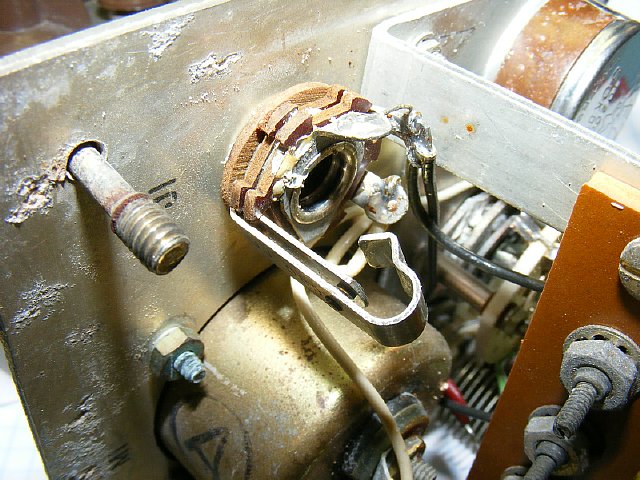
PROBLEM: The phone jack "leaf" contacts are often out of adjustment or corroded.
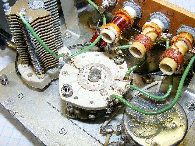
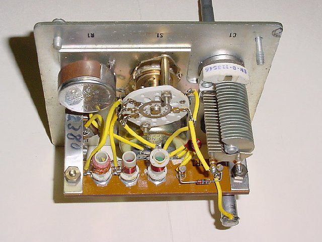
The variable capacitor C1 on the left with Band Switch and band coils in the middle. The coils can be adjusted for frequency via slug tuning. The 50K pot is on the right.
PROBLEM: The variable capacitor often has bent plates and is shorted or there is corrosion on the plates causing the capacitor to be intermittent.
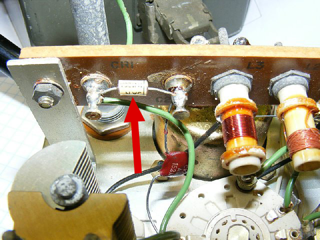
The
1N126 diode is shown above.
PROBLEM:
The diode is often bad. A suitable replacement would be any general purpose
diode but a 1N34 works well. When replacing note the correct orientation
of the black band which is the cathode. When testing the diode you
will have to lift one leg of the diode from the board.
Testing
a diode.
http://www.circuitstoday.com/how-to-test-a-diode
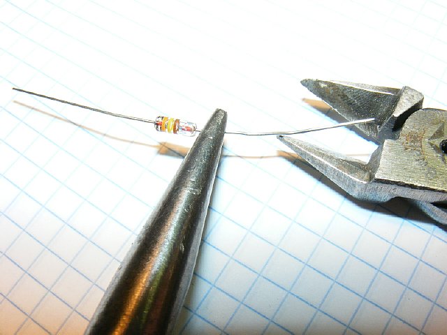
IMPORTANT TIP: When replacing the diode and clipping the leads of the new diode to the desired length use a pair of long nose pliers clamped near the diode to absorb the mechanical "shock" when clipping the lead. This prevents damage to the diode.
Chassis view of a later model. Note the smaller glass diode.

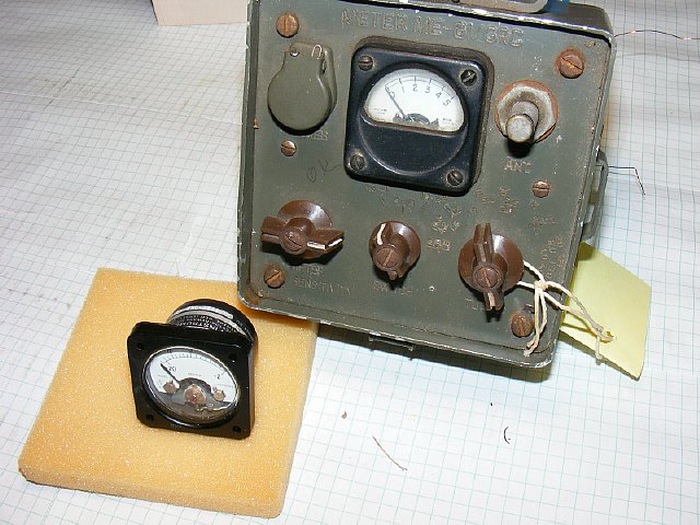
There are provisions for monitoring the audio - there are no power supplies involved so there is NO HUM. Uses a standard phone plug but with the smaller shell. The 18 inch antenna collapses into the chassis.
You can also try using the Phones jack for an external meter with a more sensitive movement . But overall the Op Amp will provide more sensitivity.

CLICK
to enlarge
Op
Am schematic and wiring connections to the ME-61. Note that the 50 K pot
has been replaced and a new 1 Meg (or 500K) pot has been utilized for
input to the LM10 Op Amp. The diode on the 9 volt line is optional but
highly recommended for reverse voltage protection. Best results obtained
when you use a Audio Taper( logarithmic) Potentiometer. Look for one with
a ON-OFF switch on the back.
Just about any diode will be OK on the 9 volt line power.
The idea to use the LM10 was obtained by visited Brooke's Military Information
page and downloading a PDF file of the mod by Mr. M. Lee.
http://www.prc68.com/I/pdf/ME61U.pdf
http://www.prc68.com/
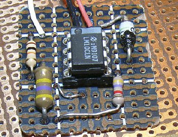
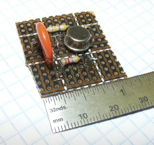
Very
few components for a lot of gain. 30-40 dB. The ugly looking diode is
the 9 volt line diode as I could not find my stash of 1N914's so just
stuck in a small power supply diode.
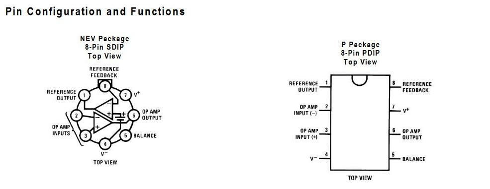
The LM10 comes in two configurations. The unique feature of the LM10 is that it only needs one DC supply or 9 volt battery. Most Op Amps require two DC sources of opposite polarity for basic DC amplification. (In other words two nine volt batteries)
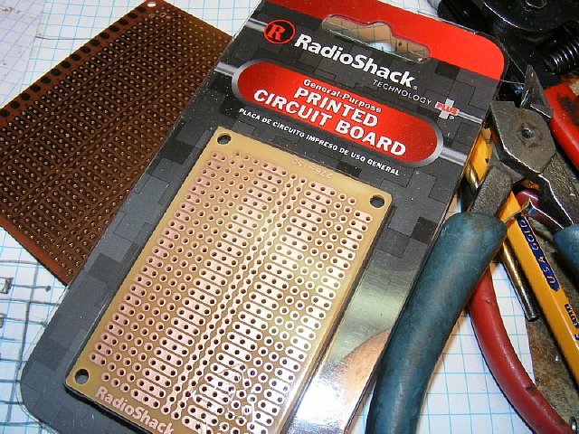
A typical multipurpose PC board. This one is available from Radio Shack part number 2760150.
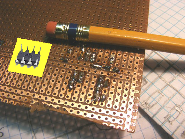
Easy to solder. The IC socket straddles the two long strips in the center running from right to left. A socket for the IC is not necessary but can be used.

You can clean the board up afterwards. Use a fine file or finger nail emory board. TEST the circuit first before cleaning up the board.
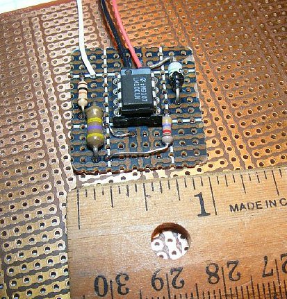
A board that measures around an inch fits nicely into the ME-61.
During evaluation I just mounted the Op Amp board to the phenolic coil and diode strip with a cable tie.
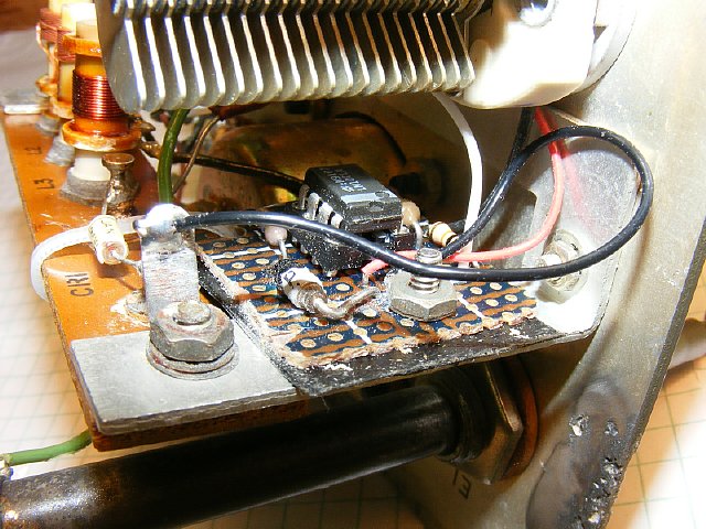
This board that measures 1 and 1/8 inches can be mounted just below the variable capacitor. I used a small 4-40 bolt but "double stick" tape would work.
The round version of the LM10 usually is soldered direct to the board without a socket as I did not have a socket. CUT OFF the unused pins to facilitate mounting.
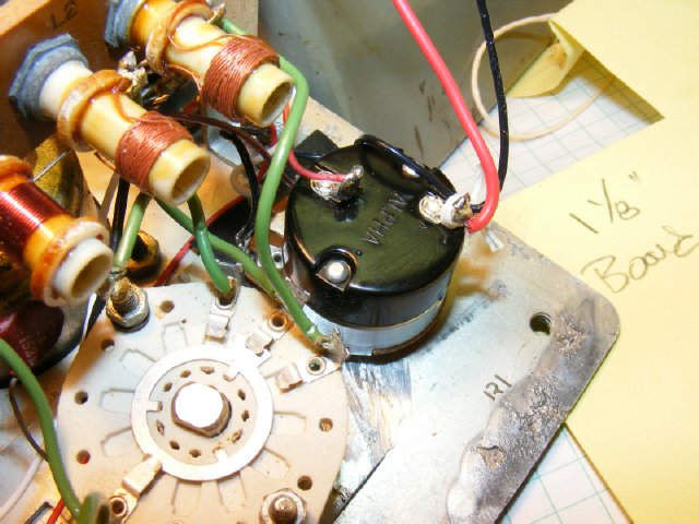
The 1 meg ohm pot installed in place of the 50K pot. Note the ON-OFF switch contacts on the rear for the 9 volt supply.
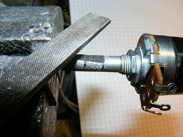
Before installing the 1 meg pot - file two flats on the 1/4 shaft so that the military knob will fit.
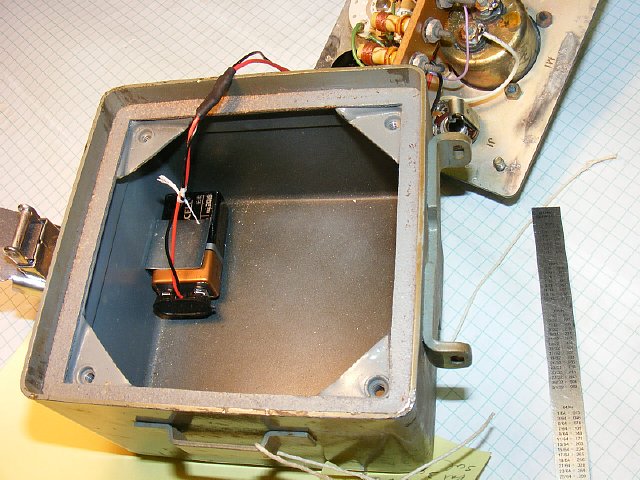
Plenty of room for the 9 volt battery.
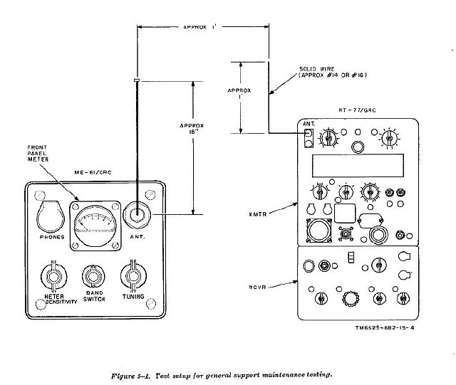
Testing procedure for the ME-61 using a GRC-9 transmitter. No sensitivity specifications were published. More info below.
A
quick way to improve sensitivity is to change out the meter. Substitute
a more sensitive meter for the 1 ma meter.
This was done and some test results of just
the basic meter change and no Op Amp are shown below. Most of the meters
you will find for use as a substitute will probably not have the 1-5 scale.
Basic METER CHANGE - change the 1 Ma meter to a 100 uA meter.

ME-61
Basic meter no changes
ME-61 Meter changed to 100 uA, no op amp .
A
comparison of range between the basic ME-61 and the ME-61 which had a
meter change to 100uA. This should give a voltage gain of 20 dB.
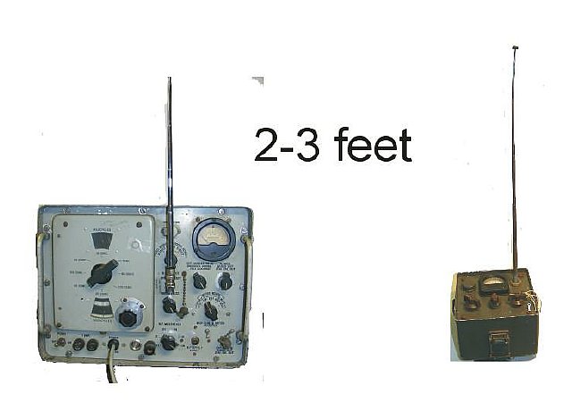
Op Amp Comparison

Op
Amp Range Comparison not in inches but in Feet.
Shown
above is is the BC-611 range on a meter with the Op Amp installed.
When tuning low powered transmitters such as the BC-611 or the Navy DAV
the further you can get from the antenna with your field strength meter
the sharpter the tuning results will be because you are in a clearer field.
A special note: With the increased sensitivity of the ME-61 using the Op Amp it is possible to use the meter on other than its designed bands. It becomes a sensitive untuned Field Strength Meter. I've tested it on 51.0 on mobile antennas and it works great - range is reduced but it is still usable as a relative meter.
Using the RF Output X-200K from the URM-25 the ME-61 with the Op Amp conversion was tested at several feet.
18
inch wire when extended.
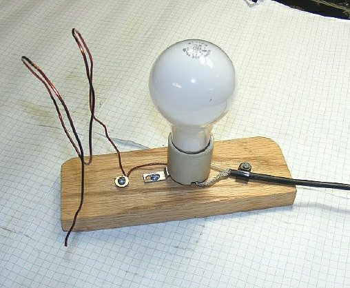
A
test jig. Using 20 watts from a transmitter and a 18 inch antenna. Antenna
is connected to the center of the coax. When using a "solid state"
transmitter you probably will need an antenna tuner to load the light
bulb.
Without the Op Amp modification the "usable reception or half scale reading" distance was about 12 inches.
With the Op Amp installed the distance was 6-8 feet for a mid scale reading- a very dramatic increase.
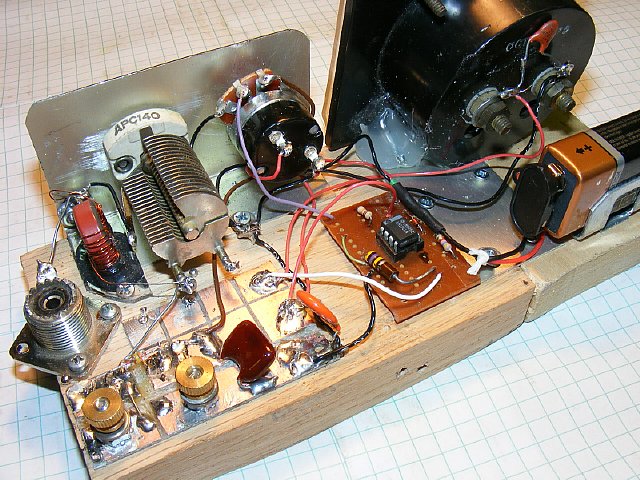
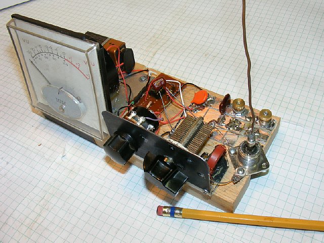
A
"bread board" version of the ME-61 with the Op Amp installed.
A junk box meter was found and installed with my faithful glue gun.
The SO-239
was mounted to a cut out in the board. A PC board was made into squares
using a Dremel tool. The knurled nuts are for wire antenna input and a
ground. The diode is mounted on the PC board between two squares. The
Variable cap is mounted to the aluminum plate and the coil using a T80-2
torrid is mounted next to the variable. The 1 meg pot is mounted next
to the variable. The Op Amp board being evaluated is in the center. Sort
of messy but I've used this bread board and metering for a lot of different
circuits.
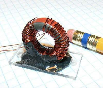
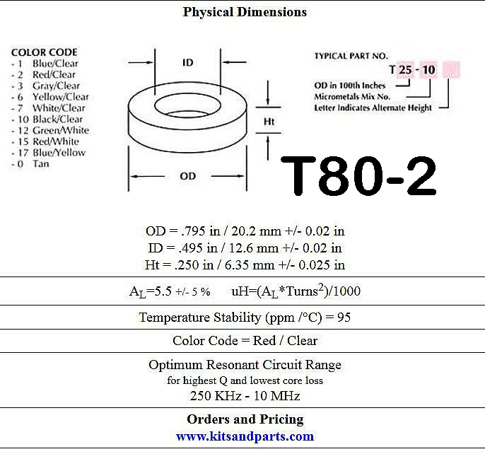
The main coil was made from a T80-2 torrid. I initially put 60 turns on but had to remove 15 turns to get the coil to tune from 3 to 7.5 Mcs. Note the method for mounted the coil makes it easy to remove or add turns. The coil was glued to a piece of lexan with JB Weld. A good target for inductance is 20-25 uH for coverage from 3 to above 7 Mcs. Most hams will not wind a coil. Its a 10 minute project when using the torrid and with this project mounting is not a problem.
T80-2. The numbers 80 stand for the Outer Diameter in 100th of inches for the core. The number 2 is the mix. See below. A T80-2 core is .8 inches in diameter.
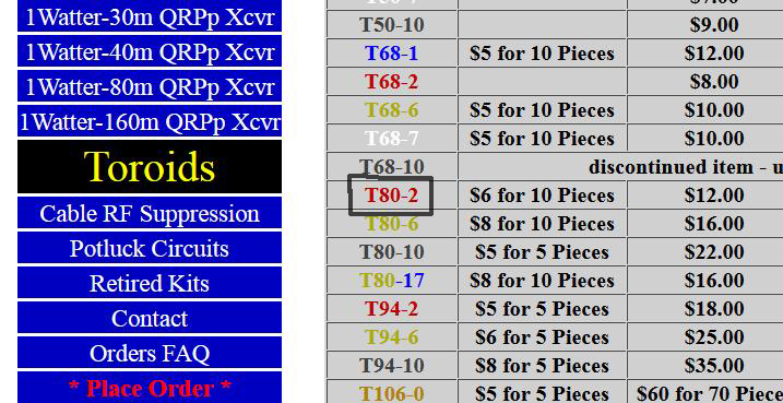
Toroid
cores can be ordered from the "Toroid King". Good prices and
excellent service. The web site is full of information on winding toroids.
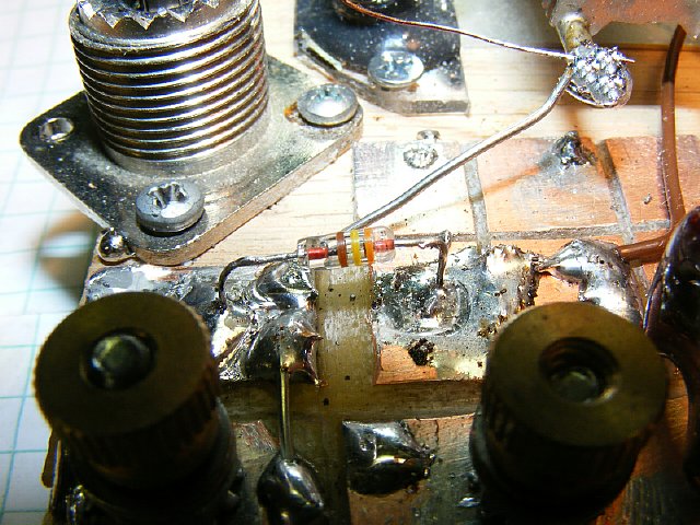
Its easy to change a diode using the PC board with squares.
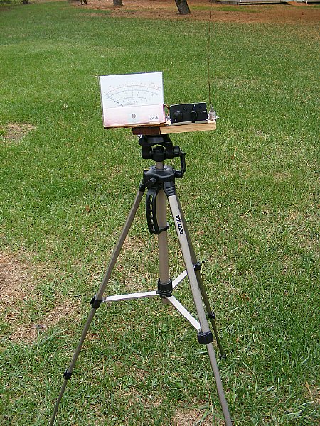
Mounting
the FS meter on a tripod comes in handy. Placing
the meter as far as possible from the antenna will result in a more accurate
measurement.
.JPG)
A 1/4 -20 "T Nut" was mounted in the bottom of the wood base.
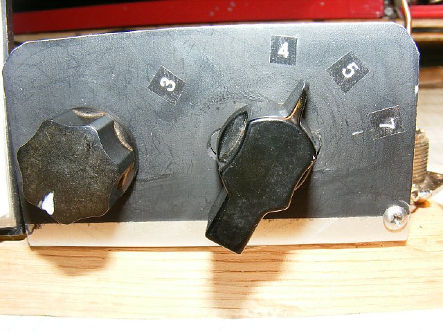
Using one coil the coverage using a 140 pf variable was from 3 to 7.5 Mc. Emergency labels were made with the Brother Label maker.
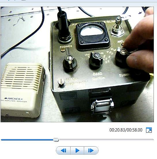
Just
for fun we made this video.
Before photo. It was very hard to read the engraved numbers.
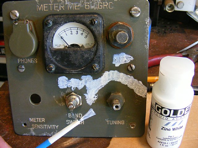
Paint the engraved letters/numbers with fluid acrylic available in the crafts section of Wally World. Let dry for approx. 2 minutes.Clean with a wet T shirt. Don't let it dry too long are you will be sorry. Play with it. Get your brushes at the "Dollar Store" 10 for a buck and then throw em away.
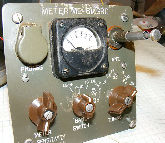
After.
Link:
Modification
of the ME-61 to cover 6 and 10 meters.
http://k4che.com/ME-61
Freq Mod.htm