 BC-221
Transmitter/VFO
BC-221
Transmitter/VFO
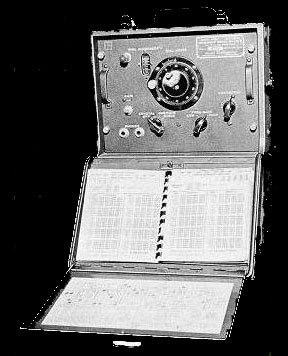 |
Here
is a chance to do something with that BC-221 that is sitting on the shelf
or buried some where in your garage or the secret storage area.
How many BC-221's or similar frequency meters do you own?
Assuming that your answer is 1 (one) then that is fine. Owning 1 (one) BC-221 is normal collector behavior.
Owning 2 (two) is a little obsessive,
3 (three) Perhaps is borderline hoarding,
Owning 4 (four) Compulsive hoarding you need therapy - recommend group sessions with other collectors.
Owning 5 (five) or more . . . You are beyond help.
A
old favorite, a friend.
The BC-221 stability and resetability to a frequency is excellent. Years ago when hams used to build things it was very common to use the BC-221 as a VFO. This required a 2 or 3 stage RF amplifier and often this BC-221-RF amplifier setup was used as a beginning stage in a multi-stage transmitter. My construction concept on these pages is to build a small RF amplifier for the BC-221 to raise the output drive sufficiently for use with some of my military crystal control equipment such as the GRC-109.
Then reading the manual I realized that it would be possible to use the BC-221 as a transceiver. Anyway I built the BC-221 RF amplifier unit shown on these pages to use the BC-221 as either a transmitter or a transceiver with 1-4 watts on 80 meters and also to use as a VFO for some of my crystal controlled transmitters driving the oscillator grids via the crystal socket without modifying the transmitter. NO modifications will be made to the BC-221. Well actually on my version of a "T" model I did make an adapter for the internal antenna connection to replace the intermitent leaf connection.
Using
the BC-221 as a receiver can be found on these pages:
BC-221
Transceiver
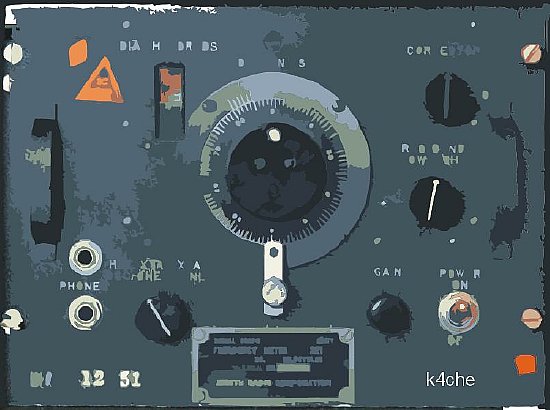
BC-221 RF Output Problem - Its very low- very very low.
BC-221 "T" model output
notes. Measuring the output of the BC-221. Using a Boonton Power Meter
4220 the measured output was -17 dbm or 18 uW. That's 17 dB below 1 milliwatt.
A milliwatt is one thousandth of a watt.
With a scope across Boonton power meter
probe driven by the BC-221 we got a voltage of .7 v PP with a probe that
is assumed to be a 50 ohm load. Measuring across the BC-221 antenna post
without a load 3 volts peak to peak was measured. An additional
check with a 50 ohm load resistor across BC-221 output resulted in .7
(point 7) PP which agreed with the Boonton power meter. In other words
the output is too low to drive anything and is useless as a stand alone
VFO to drive the average crystal controlled transmitter.
Driving an oscillator grid on a transmitter is usually via the crystal socket and can present several problems. Impedance matching using various RF transformers is usually necessary as well as developing a high enough "swing" voltage. Matching is sometimes difficult so you can just brute force it by developing enough voltage - thus the reason for these pages.
Improvise-Adapt-Overcome
![]()
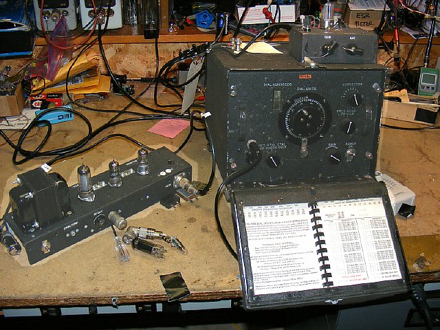
A
complete BC-221 Transceiver. VFO amplifier/transmitter on the left. A
small single tube RF amplifier for the "receive" section is
sitting on top of the BC-221. T/R switching is accomplished by a simple
slide switch.
QST pages and articles shown here with permission of the American Radio Relay League. The ARRL Periodicals Archive and Search site is an excellent technical resource.
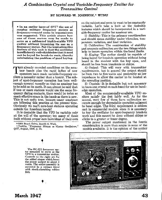
It
was common practice to rack mount the BC-221 and its RF amplifier.
A link to the complete article is posted below.

CLICK to enlarge
Howard Johnson W7NU designed a nice unit that served both as a VFO and as a low powered crystal controlled transmitter. Output was stated as 3 watts. The schematic shown here uses the BC-221 to drive a 3 stage RF amplifier.The schematic shown above is a little daunting for the average builder so I simplified it a little bit. See below.
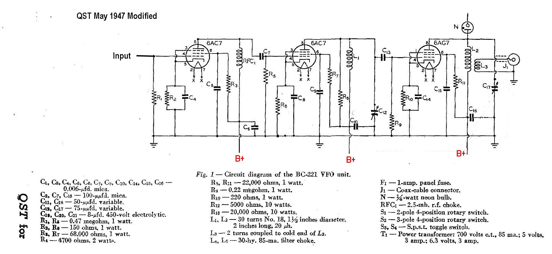
CLICK to enlarge
Here is the same circuit after I removed the crystal oscillator switching and power supply.The circuit is a 2 tube 6AC7 amplifier driving a ham favorite a 6AG7. The BC-221 is fed to the input via a short piece of RG-58 or similar shielded cable. Power output can be 3-4 watts and PP voltages as high as 100 volts unloaded. There is more than enough voltage swing to drive any crystal controlled transmitter via the crystal socket without modifications. The 3 watts can also be used for QRP operations on 80 meters. There are two frequency ranges for the BC-221 125-250 kcs and 2.000- 4.000 Mc.
Please note that the first two stages
shown in the above QST schematic are not tuned for resonance and what
I call brute force coupling is used. I prefer to have my stages resonant
and to be able to peak the stages for maximum output if I move from the
low end of 80 to 75 Meters. Further schematics below.
The
complete article courtesy of ARRL can be found here:
QST May 1947, "The BC-221 Combination Crystal and Variable Frequency Exciter"
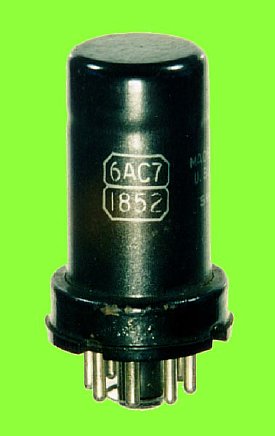
The 6AC7 utilized for the first two stages in the previous QST schematic is a large 8 pin octal base tube.
 Click to enlarge
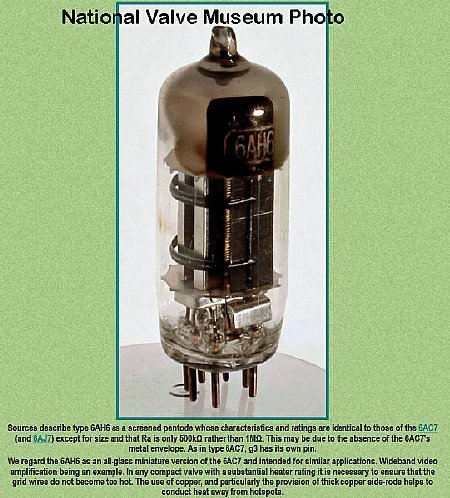
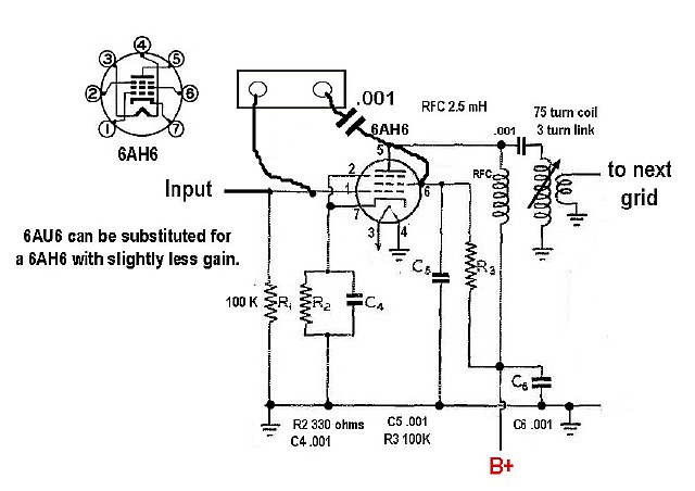
 The 6AH6 operating and electrical characteristics are identical to the 6AC7. I had used a miniature tube in my BC-221 RF preamp so I chose the same physical size 6AH6 for the first two stages of this project. Note: A 6AU6 may also be utilized but with slightly less gain.
BC-221 RF preamp project
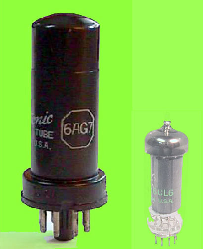
6AG7 6CL6
The 6AG7 can be replaced with a minature glass envelope 9 pin 6CL6. The 6CL6 is an excellent power amplifier and has been very popular in amateur transmitters.
CLICK to enlarge
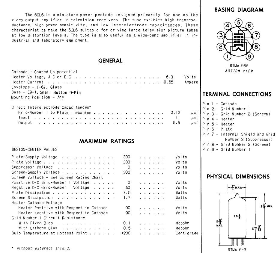
6CL6 data
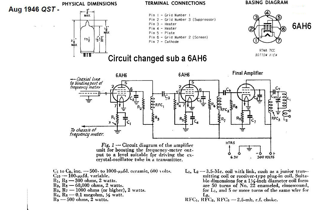
Here is another article (schematic shown below) for using the BC-221 as a "Master Oscillator".
CLICK to enlarge
I subbed the 6AH6 for the 6AC7 on the schematic. The final amplifier in the article was suggested to be any power tube such as a 6L6. Again the 6AH6 stages in the circuit show above are not tuned to resonance.
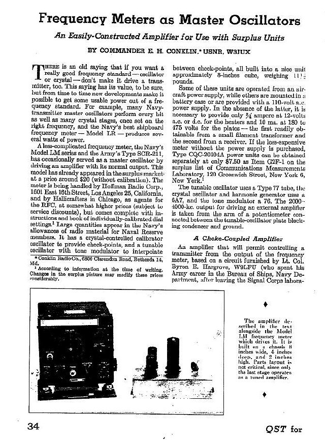
QST August 1946. "Frequency Meters as Master Oscillators."
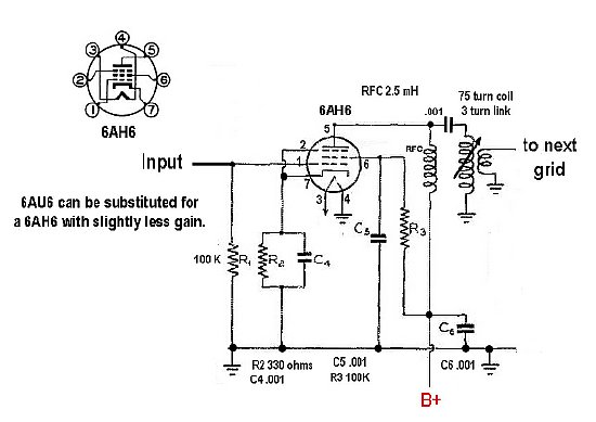
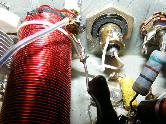
My
version of the 6AH6 stage. Later on I added a 5-10 pF fixed capacitor
across the 75 turn coil to allow the tuning slug to be positioned in the
center of the coil when the circuit was peaked this allowed complete coverage
of 3.5 to 4.0 Mcs.
Possibly try 85-90 turns for the coil to eliminate the fixed capacitor.
My B plus supply was 340 volts which was a little high so I increased
screen resistance to 100K. Note that link coupling is used to couple
from the 75 turn coil to the grid of the next stage.
I've always had great success with link coupling especially on VHF circuits. I found that the link coupling on these 6AH6 circuits reduced the chance of spurs, provided more output, and improved tuning of the stage and to quote Mike Hanz KC4TOS "As to the link coupling, it has been preferred for amplifiers for all power levels power since the 1930s for the reason you discovered - it increases the stage Q and thus narrows the bandwidth considerably."
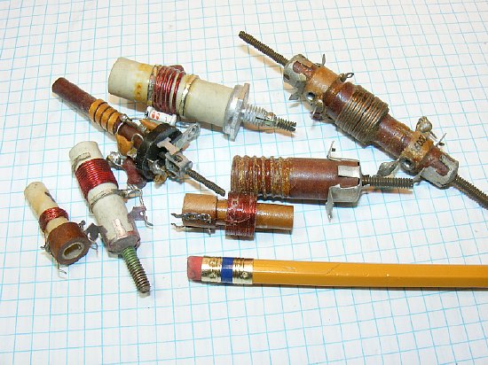
Quarter inch coil forms any of which could be used for this project by removing existing windings and rewinding. Look at the picture - what doesn't belong ?
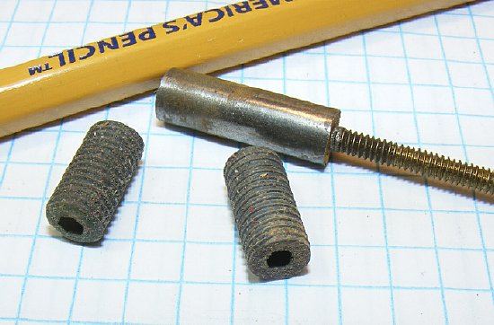
Typical tuning slugs. I prefer the slug with the threaded bolt 6-32 shaft as the shaft extends above the chassis and you can use a small screw driver for tuning. The other slugs require a plastic tuning tool. In either case the slugs move up and down inside the 1/4 inch coil form.
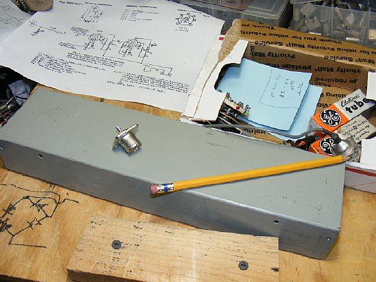
"I love the sight of a blank chassis in the morning." My handy drawing of a diode bridge circuit will be used later.
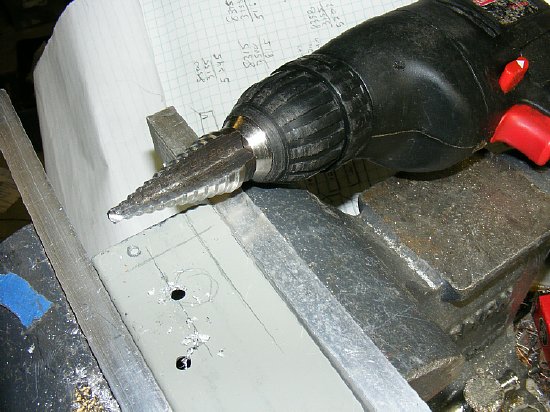
My favorite chassis tool the "Unibit" aka Vari-bit or step drill. Be careful - be sure and mount that chassis in a vice before using the drill on "slow" speed. Hang on. Prevent a trip to the local Emergency Room.
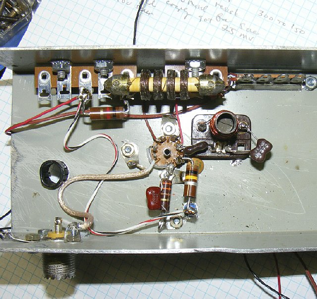
1st stage completed. I added a 5 pF brown mica cap across the tuning coil after testing to allow the slug to be in the mid portion of the coil windings instead of near the bottom. Your mica cap can be any color but is usually brown. The coil probably needs 85 turns instead of 75. The BC-221 RF input SO-239 is shown on the bottom left.
A grid dip meter comes in handy. You can get a feel for the circuit without applying power and besides a real radio man has a grid dip meter. Cheeep - $10 at a hamfest because no one wants grid dip meter or even knows how to use one. A lost art.
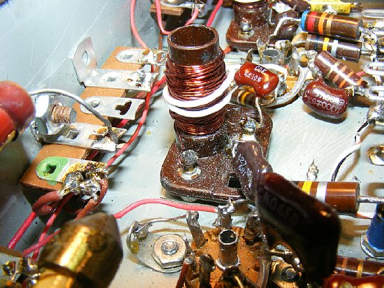
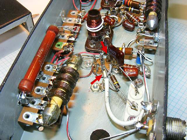
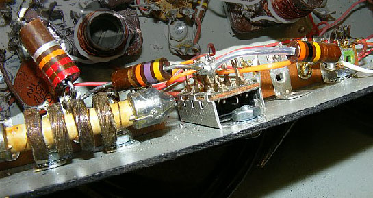
Link coupling
is simple. 2-3 turns with one end grounded and the other end to the grid
of the next tube. Note the use of mounting strips on the side and ground
lugs on the tube socket bolts. Each time you install a tube socket put
ground lugs on each mount. That first terminal on the left strip looks
a little messy as I used that as a B plus distribution point to each stage
of the amplifier. The lug allows soldering and desoldering of the B+ feed
lines to the different stages to check current etc. Note that ground lug
on the tube socket might use a little more heat - a possible cold solder
joint.
TIP: Each time you initially install a tube socket put ground lugs under each nut.

Click to enlarge
AA8V 6AG7 schematic modified by K4CHE.
The final amplifier using a 6CL6. Excellent site for constructing a 6AG7 amplifier by AA8V. He has a lot of information for the Novice builder.
http://faculty.frostburg.edu/phys/latta/ee/6ag7amp/6ag7amp.html
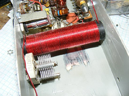
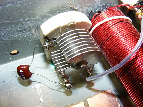
The final coil was wound on 1/2 inch polyethylene pipe stock . Go to Lowe's and buy 2 feet and you will have a supply that should last you for a while.
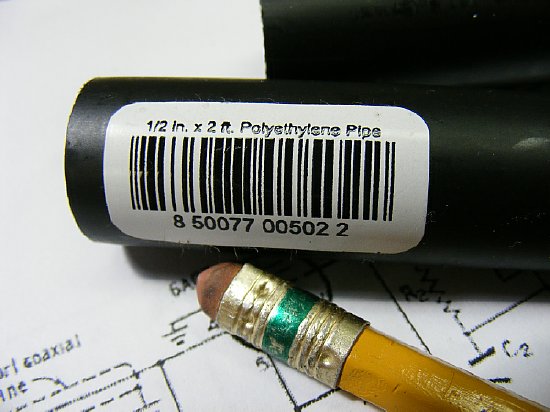
Lowe's or Home Depot
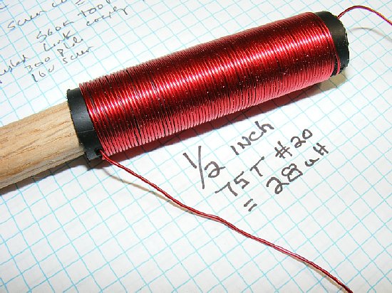
75 Turns. A short section of a wood dowel is inserted in each end and trimmed flush.
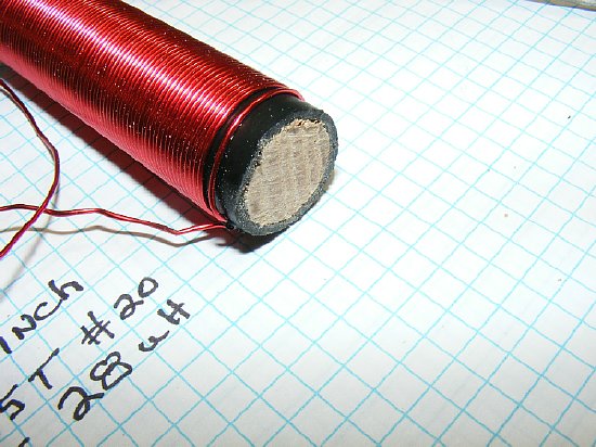
The cut off wood dowel allows for easy mounting. Use wood screws through the side of the chassis.
Wood screws through the sides of the chassis and the coil is mounted.
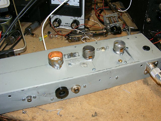
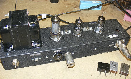
Making
progress. Three tube sockets on top are the 9 pin for the 6CL6 and two
7 pin sockets for the 6AH6's. The 6/32 shafts can be seen for 1/4 inch
tuning coils.
TIP: Build and trouble shoot one stage at a time. Keep a neat work bench.
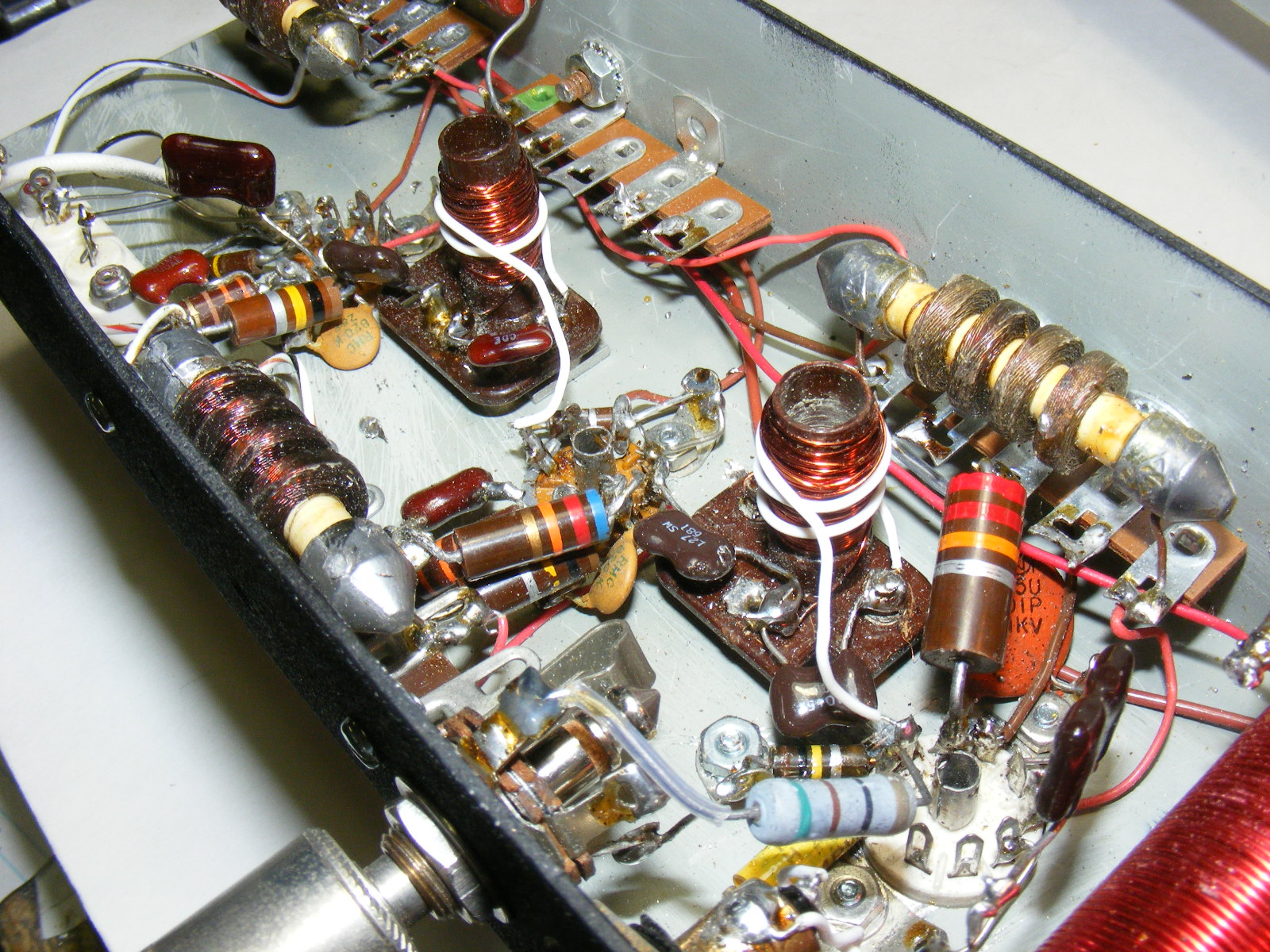
CLICK to enlarge
The 6CL6 9 pin socket is located at the bottom right. Link coupling was used to feed the grid from the coil of the previous 6AH6 stage. (white wire) Link coupling allowed much sharper tuning and better drive. I don't know what all those white specs are on the coil base - some kind of dandruff and it wouldn't brush off.
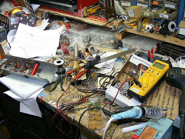
A neat and well organized work bench is the secret to a successful construction project.
A #47 or #49 light bulb comes in handy to monitor the final amplifier tuning. Use a portion of a modified fuse holder to make a "k4che holder" to house the bulb.
My first attempt was putting a #49 bulb in series with the cathode which is an old trick to monitor plate current - - - actually the total plate and screen current and it worked OK as you could detect minimum plate current by watching the bulb dim very slightly as you tuned through resonance but this was not very dramatic and was kind of hard to see. Tried a neon bulb but that was worse. Or you can use a actual milliamp current meter 0-50 Ma mounted on the chassis but preferred to keep it simple. Later I changed the circuit to sample actual RF output from the final coil.
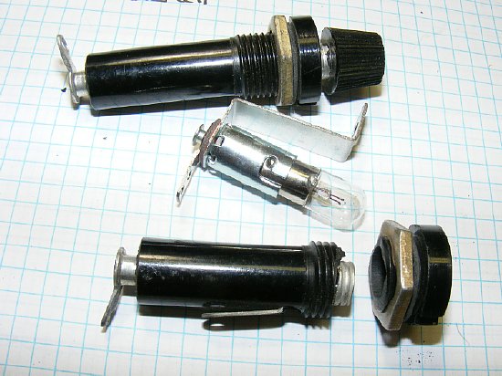
A fuse holder body makes a panel mounted bulb holder.
A
standard bulb holder inside a portion of the fuse holder. But too complicated
and I was running out of room inside the chassis near the final tank coil
and didn't really want that metal bulb socket and bracket right next to
the tank coil. The light bulb socket was removed and the bare bulb was
inserted into the k4che light bulb fuse holder. KISS
Final
version. Bulb fits in the k4che bulb holder that has had the inner diameter
enlarged slightly with a round file. A one (1) turn link on the 6CL6 final
coil was installed to sample the RF.
A #49 bulb was used which
is rated at 2 volts and .06 amps which equals .12 watts at full brilliance.
A #47 bulb is rated at 6.3 volts
and .945 watts and consumes more power. If the idea of the bulb glowing
and stealing some of your power bothers you and keeps you awake at night
then just put a small toggle switch in the sampling link to disconnect
the bulb after tuning has been completed. Note the cathode resistor is
on the right and goes go the phone jack for keying of the cathode circuit.
I did not have a 100 pF variable for final 6CL6 tuning so I used a 40 pF variable and put another brown mica 30 pF fix cap across it to tune the final. Any color mica can be used. This gave me 40 to 70 pF for tuning which covered all of the 80 meter band and was close enough for "Government Work."
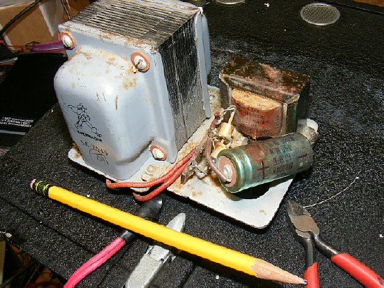
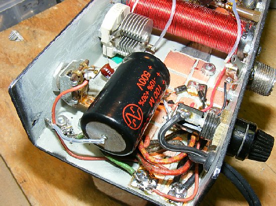
As the project progressed it was time to start thinking about a power supply. I resurrected a transformer from my old KW6 Wake Island Command Set receiver supply which is shown above. This power supply mounted on the rear of a Command Set receiver in place of the dynamotor. I used the receiver on 40 and with a converter on 20 meters and a smal WRL transmitter all of which was packed into a suit case. While staging crews and waiting for the next aircraft at Wake Island you could fish all day and play with radio all night and in between maybe a make few trips to "Drifter's Reef." Anyway enough of this folderol.
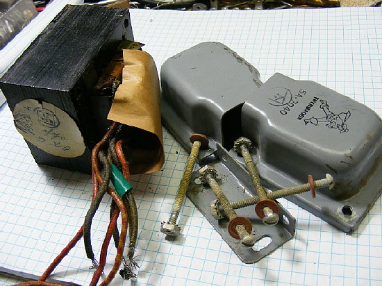
The transformer windings were inspected and a check was made from the windings to the metal core for possible shorts or leakage. The transformer provided voltage of 700 volts with a center tap and my plan was just to use one half of the secondary and feed the 350 volts to a full wave bridge.
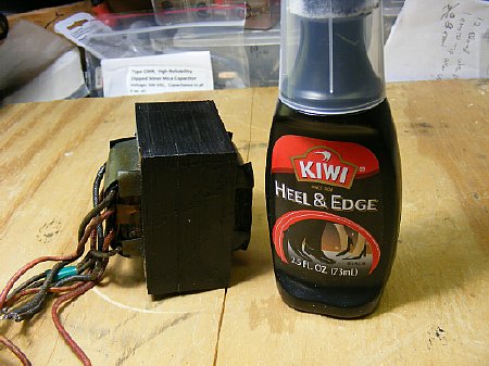
While I had the transformer disassembled I touched up the core laminated plates with some shoe and boot heel dye which is and ole timers trick probably published in "Hints and Kinks" many years ago. If you paint the laminated plates with enamel or similar paint the smell is terrible when the transformer heats up and the paint starts to do weird things but the Kiwi heel dye evaporates and is not effected very much by the heat.
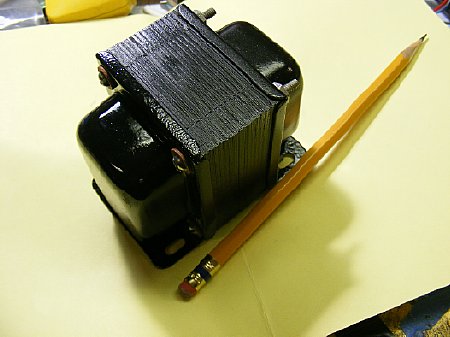
and might as well paint the outer shell while it is disassembled.
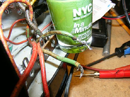
While I had the transformer leads positively identified I color coded them.
TIP: Establish a personal color code. Green for filament, red for B plus, blue for bias, yellow for pizza. Use cheap fingernail polish from Wally World - have your wife purchase the fingernail polish otherwise you get those strange looks.
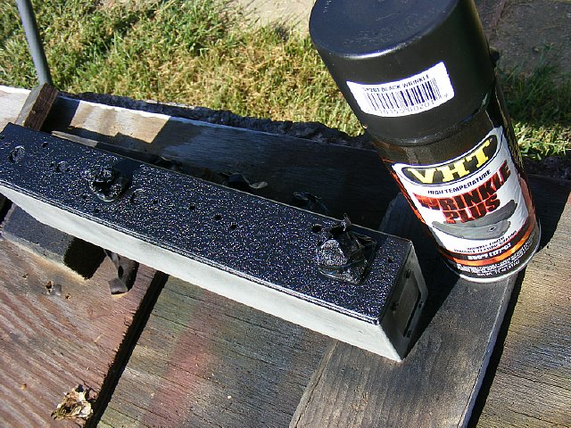
Before
I mounted the transformer the chassis was painted with black wrinkle.
Auto Zone has the VHT Wrinkle Plus paint which it is the best black wrinkle
I have ever used.
"I love the smell of black wrinkle in the morning."
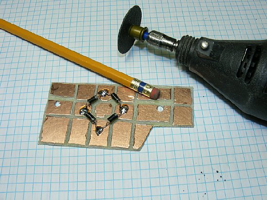
I prefer a full wave bridge rectifier . The PC board shown has soldering squares that were cut with the Dremel tool and be sure and wear safety glasses. Extra squares for components to be added if necessary. The diodes are arranged in a "bridge" to make it look like the diagram. This method of mounting allows easy solder and desoldering in case you have to trouble shoot the diodes.
TIP: Keep a good supply of safety goggles or glasses- have more than one pair and keep a pair near each work area.
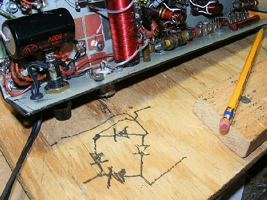
My diode bridge drawing on the work bench comes in handy. This drawing will probably be found in a thousand years and they will try to figure out what it means that is after they figure out the meaning or use of billions of metal coat hangers and beer cans that they have uncovered.
A simple filter with just a 100 uF cap across the output of the bridge. I did not use a choke. Note that some of the "Dremel" squares on my PC board came in handy and served as solder tabs for wiring the transformer leads and the AC input wiring. A generous solder blob on each pad holds the wires in place. A standard fuse holder for a 1 amp fuse is mounted on the side.

A
simple L network was used to match the output of the 6CL6 to 50 ohms -
this arrangement was selected as the R input (6CL6 output) is higher than
the output load resistance (high to low) which is assumed to be a 50 ohm
system. The inductor itself does not have any taps. In the event the R
Input were smaller than the load resistance then the capacitor would have
been placed on the other side of the inductor.
TIP: If you had taps on L1 and constructed this circuit in a small handy
box it would make a nice "simple" antenna tuner keeping in mind
that you could always switch the input and the output to satisfy different
input/output conditions.
TIP:
You can utilized any antenna tune backwards to match strange loads.
The 2.5 mH choke is optional
but AA8V's excellent site (link below) below explains why it can be important.
Go to the site and click on the schematic.
http://faculty.frostburg.edu/phys/latta/ee/6ag7amp/schematic/
An "emergency"
crystal socket was installed and connected to pins 1 and 6 on the first
6AH6 stage with a .001 capacitor between pin 6 and and the crystal socket.
Crystal current was checked and it was very small so you could get a way
with one of the "stuffed" FT-243s. So now the amplifier serves
two purposes it can be used as a RF amp for the BC-221 or a stand alone
crystal controlled CW transmitter.
When using a crystal you may have to retune
the first 6AH6 stage slightly for stable oscillation but it was possible
to adjust the first stage coil where you can use either the BC-221 input
or the crystal. When crystal operation is desired plug in a crystal and
disconnect the BC-221 input otherwise strange and interesting radioing
things happen. Play with it.
Crystal socket installation with the socket connected to pins 1 and 6 of the first stage. A .001 capacitor was used.
A #47 bulb (6.3 volts .95 watts) can be used as a test load. Its resistance when lit is approximately 40 ohms. Put a 47 ohm resistor in series to prevent burning out the bulb. The "L" network will easily tune this resistive load of approximately 80 ohms.
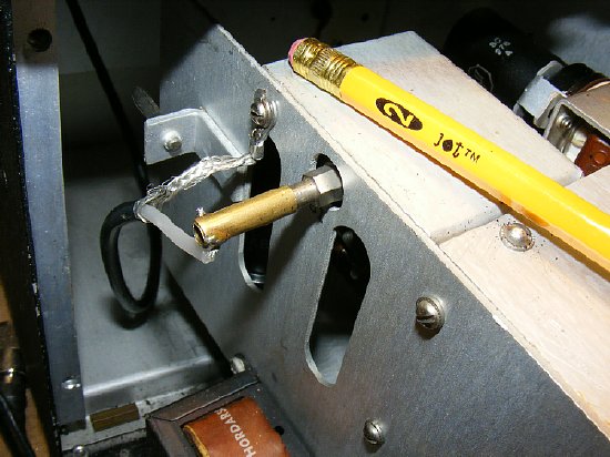
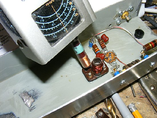
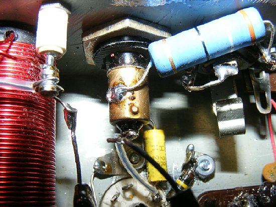
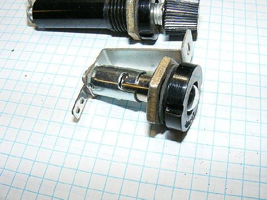
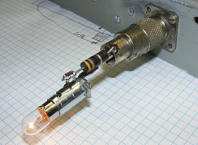
My BC-221 "T"/TS-164 model has
an binding post antenna terminal on top of the case with a contact post
mounted on the side of the main RF chassis which is shown above - when
the main chassis was inserted into the case a leaf spring was supposed
to make contact. This leaf spring was cleaned and adjusted but still found
to be intermittent. Probably the reason that on other models the designers
put the antenna terminal on the front of the BC-221 RF chassis. Anyway
I removed the leaf and then fabricated a slip on connector out of brass
tubing (7/32) and used a short piece of RG-58 connected to the top connector
on the case. This slip on connector comes in handy as it can be easily
removed when the main chassis is removed from the case.
TIP: Lay in a supply
of different sizes of brass tubing, The stock comes in handy for emergency
connectors etc. Hobby Lobby or any hobby store. Micro Mark has an assortment
available.
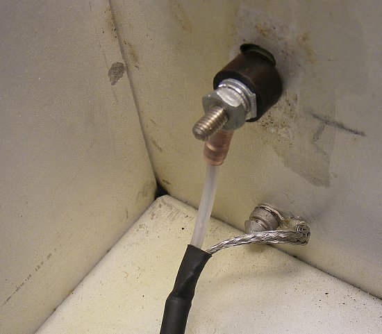
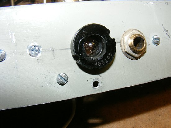
Cable connections via RG-58. The terminal shown is a "inside" view of the antenna binding post mounted on top of the case of my BC-221/TS-164
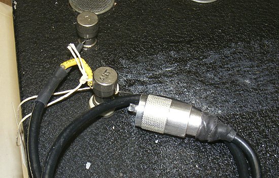
The top side of the TS-164 case with an antenna terminal and ground. A short cable has been fabricated to connect from the binding post terminals to the 3 tube Transmitter/VFO amplifier. When used as a transceiver a small slide switch is mounted

A simple slide switch was used to switch the output/input of the BC-221 and to switch the antenna from transmit to receive.
After testing the unit I decided to install a slide switch to select different screen resistor combinations. 300K,47K and 22K provided a nice range of screen voltage. The switch selects all three in series for a "low" output. The 47K and 22K in series are selected for medium power and the 22 K is selected for full or high power.
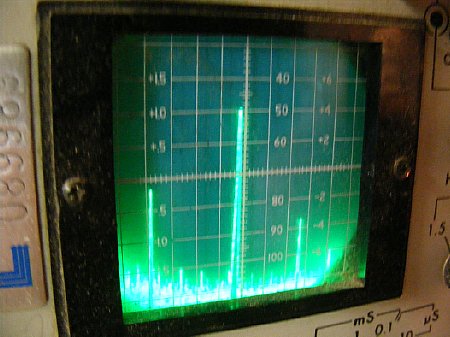
The 2nd harmonic on 40 was an easy 30-40 dB down which exceeds the 5 watt requirement. Add an antenna tuner and pick up another 15 dB 2nd harmonic attenuation. If you are worried about the 2nd harmonic on 40 meters when transmitting on 80 then call CQ on 80 and listen on both bands for an answer twice the fun.
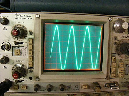
RF
Output Voltage measurements:
80-90
volts peak to peak is available when transmitting into the bulb dummy
load. When lowering the screen voltage
on the 6CL6 with the high low switch the voltage is reduced to 15 volts
PP. Plenty of voltage to drive anything. You can always detune the stage
feeding the 6CL6 final to adjust the output voltage.
An easy 4 watts.
Final tuning tip: When operating transceive with the BC-221 Transmitter/VFO and RF preamp described on these pages you should tune in the signal then find zero beat and then tune slightly off to one side keeping in mind that if you tune off to one side to produce a 1 kc (1000 cycle) audio note then your transmission will be "off frequency" by that amount. If you and your dog like the high frequencies say 3000 cycles then you may be so far off frequency that no one will hear you thanks to modern receivers and filters etc. In other words there is no CW offset and the receiver is a Direct Conversion Receiver. Best to just tune off enough to hear the CW transmission say 300 to 500 cycles so that when operating transceive your transmit signal will be close. 300 cycles in my case is fine as I've lost a lot of my high frequency hearing thanks to beaucoup hours in the cockpit.
Return to K4CHE Index