 BC-221 "Transceiver"
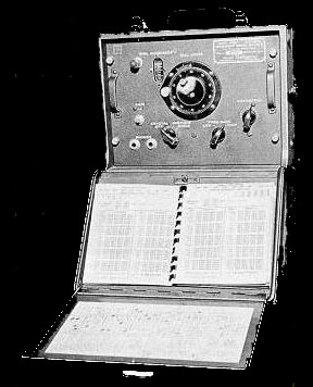
A
suggestion: Get that frequency meter off the shelf and into operation
i.e. do something with it - on these pages I offer an alternative use
for the SCR-211 or similar sets .
I have 3 of these meters all of which were picked up at local hamfests
and military rallies for an average price of free to $5 - one meter was
being thrown away - the seller had $15 on it and no buyers - I rescued
the set from the trash barrel.
FLASH: K4CHE checks into the OMRN Sunday night CW net with the BC-221.
My CW operating position for the OMRN Sunday night CW net.
A BC-221 Transceiver System
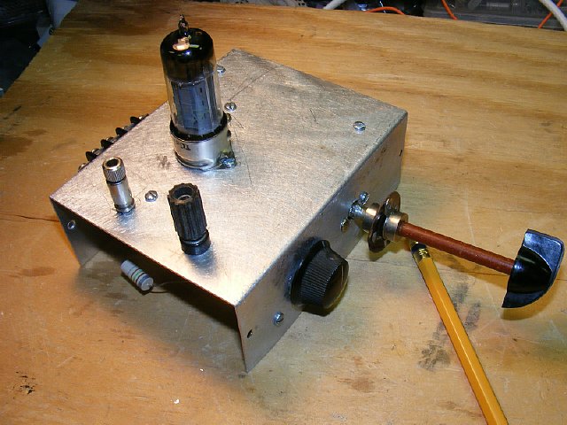
This project began as a simple RF amplifier for the BC-221 Frequency Meter so that it would have enough drive for frequency control (VFO) on several of my transmitters such as the RS-6 and GRC-109 but like all projects that are started a side project spawned and and the idea of a BC-221 transceiver was launched . Please don't expect a complete revamping and modification of the BC-221 to produce a transceiver equal to your Japaneese Rice Box or your Transworld TW100 but do count on using your BC-221 as very stable oscillator-detector- audio stage for a simple low powered CW transceiver. NO modifications to the BC-221 are made and the frequency meter is used as is.
The MRCA CW Sunday night net NCS is Ted W3PWW and the frequency is 3570 kcs. Ted also conducts the Saturday morning AM with carrier net on 3885 at 0500. In the past I have been successful in checking into the CW net with various odd ball, strange, weird, interesting, controversial and unconventional military receiver and transmitter combinations . I mean you have to do something different on a Sunday night just to stay awake during the net after a long weekend. One of my check ins was accomplished using a Pogo Stick (see link). Another example of an unique check in was Rob Flory K2WI who checked into the net keying a Northern Variable Master Oscillator. So I thought I would use a BC-221 as a transmitter and check into the net and use a separate receiver but then the transceiver project started.
http://k4che.com/Pogo/Pogopg1.htm
http://www.mrca.ar88.net/Nets/default.html
Some Page Notes
Info on using the BC-221 as a receiver
and as a "transceiver" is presented on these pages but if you
want to skip the receiver info due to lack of interest you can go to using
the BC-221 as a very stable VFO that will drive the socks off of any crystal
controlled transmitter that is in your inventory.
BC-221
Transmitter/VFO
If
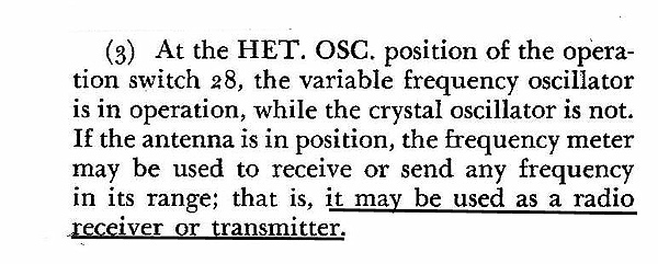
all else fails RTFM. After reading though the manual the BC-221
transceiver project was born - Instead of just using the BC-221 as a transmitter
why not use it as a transceiver. Obviously the BC-221 frequency meter
circuit is easy to tune, accurate, and develops very little drift and
the resulting transmission or reception would be very stable in frequency.

Click to Enlarge
Its all there. Oscillator-Detector Mixer-Audio Amplifier. Oscillator range is 125 to 250 and 2000 to 4000 kcs on a typical BC-221.
Click
to enlarge
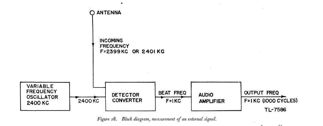
Block
diagram illustrating the mixing/detection of an incoming signal with the
variable frequency oscillator resulting in a Direct Conversion Receiver*.
Note that when you detect a signal you will be able to tune either side
of "zero beat" for both lower and upper side bands.
*A direct-conversion receiver (DCR), also known as synchrodyne, or zero-IF receiver and thanks to Perry W8AU for reminding me of the DCR term.
BC-221
Experiment # 1. Hook up an antenna to the input of the BC-221,
plug in the ear phones and listen very carefully and tune around 3500
to 3600 Kcs. Its kind of like listening to a crystal set. On the East
Coast in the evening W1AW sends various practice CW text from QST magazine
at different speeds on frequency 3.5815 with a good antenna you should
be able to hear them. Frequency link below.
Regardless you should be able to hear some
very weak CW signals. Hook up an some sort of antenna tuner or "Transmatch"
and the signals will pick up. Audio will be weak just like that crystal
set you built as a kid - - very weak but you should be able to hear something!
Tests conducted with a signal generator show a minimum signal detection
by ear to be around 500 to 1000 uV. But add the trusty
Rad Shack mini audio amp to the output jack you can detect signals down
to 100 to 200 uV. . . and thus the project begins. Selectivity is also
very broad with nearby signals easily heard in the back ground. So we
have a minor BC-221 receiver problem mainly with sensitivity and perhaps
selectivity.
QST pages and articles shown here with the courtesy and "permission" of the American Radio Relay League. The ARRL Periodicals Archive and Search site is an excellent technical resource.
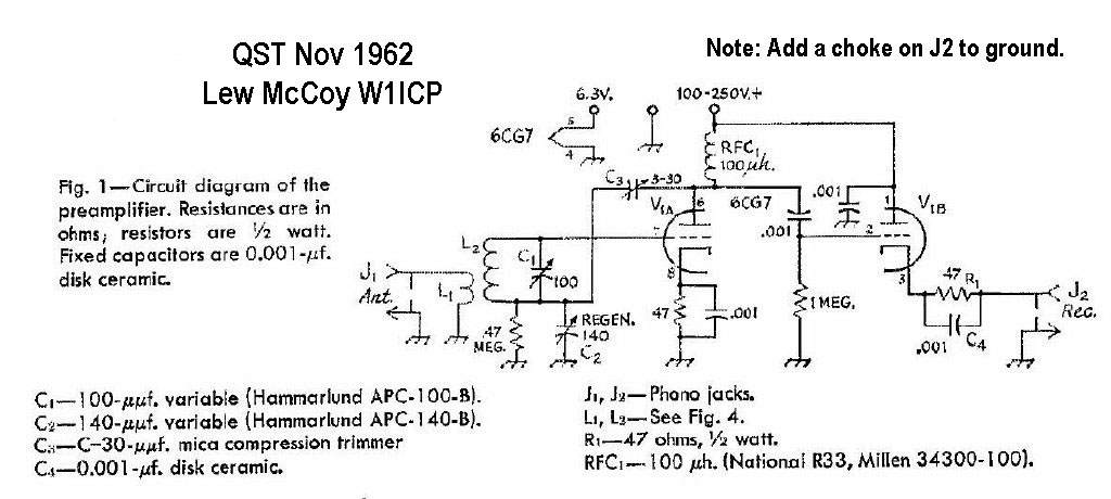
QST article and info courtesy of American Radio Relay League. QST Magazine November 1962.
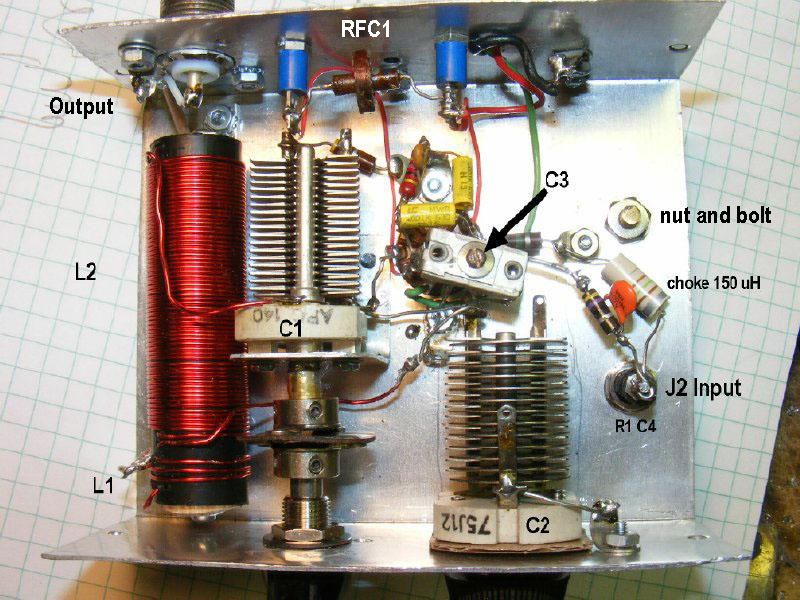
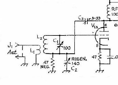
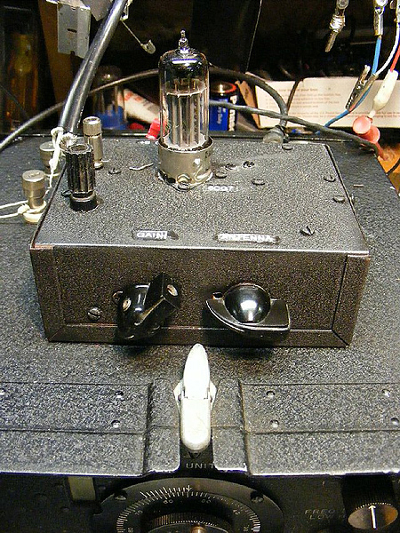
After hearing signals on the 'barefoot" BC-221 I decided that an additional "Tuned" RF Amplifier would be helpful on the BC-221 antenna input. Years ago Lewis McCoy W1ICP designed a single tube "regenerative" preselector (RF amp) that became very popular. It was simple, easy to build and provided a enormous gain for the front end of the average receiver and the best part was it was adjustable and had a tuned circuit on the antenna input which would help with selectivity.
 Click to Enlarge
Schematic
courtesy ARRL. QST magazine November 1962.
Its
a fairly simple circuit and a two night project if you have all the parts.
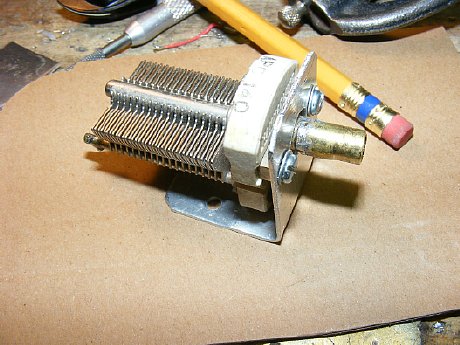
Coil L1-L2 is easily fabricated for 80 meters (more info below) and the
variable capacitors can be found on ePay. Power for the preamp will be
taken from the typical AC supply built into the rear of the BC-221. The
6CG7 tube is a miniature version of an old favorite the octal based 6SN7.
The tuned antenna input section improves selectivity.
I like
Lew's circuit because you can optimize gain by carefully adjusting the
regen control and antenna control and it is obvious when you have gone
to far as the circuit will pop into oscillation so the best gain is just
below that point and it takes some careful tuning - if you don't have
any patience or don't want to experiment then the circuit is not for you.
However stick with it and you will be rewarded with over 20dB of gain
and besides operating the regen control and carefully tuning the input
makes you feel like you are doing some real * "radioing."
* Note:
The term "Radioing" is a term often used in the k4che Operations
Center.
Note: Using this
preamp on the BC-221 will require a choke installed from the J2 output
to ground to provide DC return for the cathode of V1B. The choke is not
shown on the "original" schematic but is mentioned in the text.
The value is not critical. More info below.
Schematic and information
courtesy of ARRL. Link here for the PDF file of this project.
PDF file Lew McCoy's Preselector Courtesy of the American Radio Relay League.
.JPG)
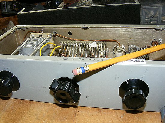
50 turns for L2 and 3 turns for the coupling link L1 antenna input results in a high Q coil with plenty of coverage from approximately 3 to 6 Mcs.
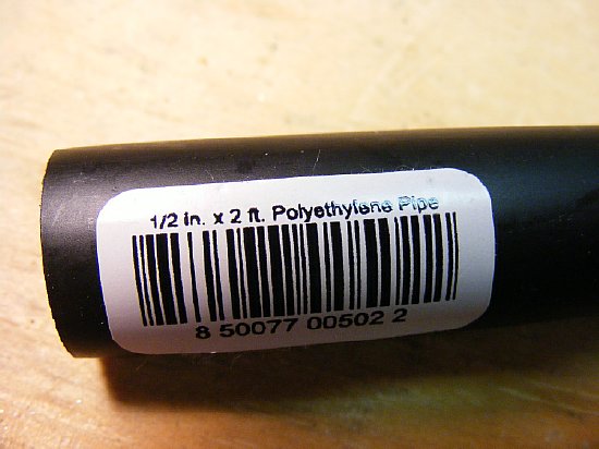
Lowe's or Home Depot.
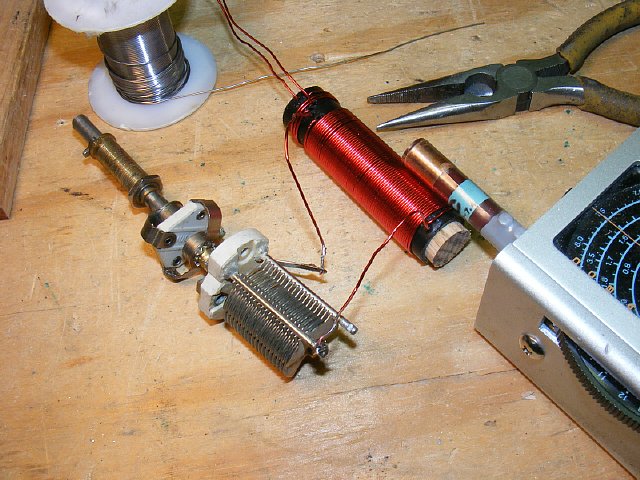
A grid dip meter comes in handy to check the range of fabricated coils.
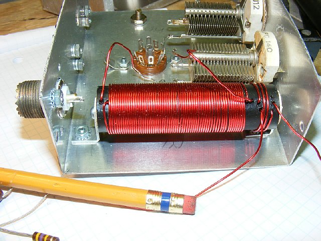
Small brackets hold the coil. The antenna tuning capacitor C1 was originally mounted next to the coil via the front panel but this location was changed. More info on the location of C1 below.
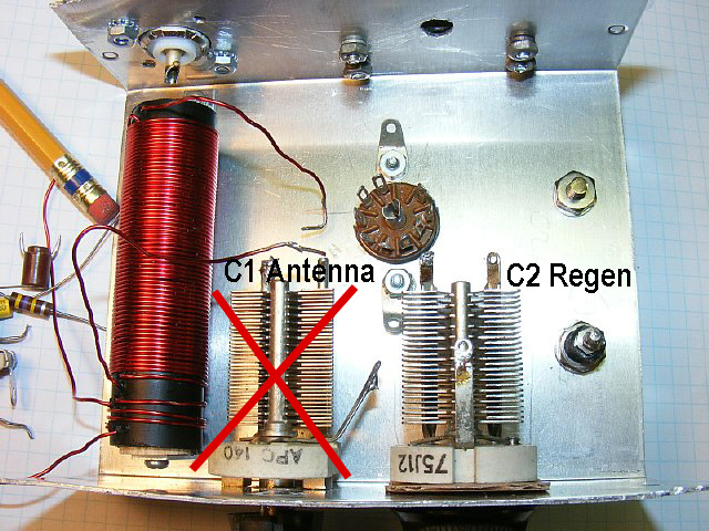
And now the bad news. Mounting the antenna input capacitor C1 on the front panel did not work due to the problem of hand capacitance when tuning. I should have known better.
A trail to confirm that the circuit was operating required an insulated shaft on C1 the antenna variable capacitor to avoid detuning the circuit with hand capacitance. There was no problem with the Regen control on the left and it remains mounted to the front of the chassis. So C1 had to be mounted inside the chassis. I should have paid more attention to the article.
 Click to enlarge
QST
November 1961
Here is the under chassis photo from
the article. C1 is mounted inside the chassis on a bracket.
A piece of 1/4 brass tubing was fitted to the capacitor and soldered in place to provide a shaft and then the capacitor was mounted inside the chassis on a bracket. A 1/4 inch insulated shaft coupling was used with a 1/4 shaft to provide tuning from the front of the chassis.
Adapt-Improvise-Overcome.
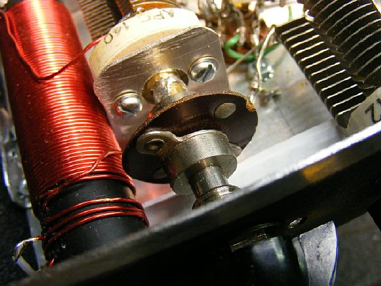
C1 mounting details and installation of a 1/4 inch "insulated" coupling.
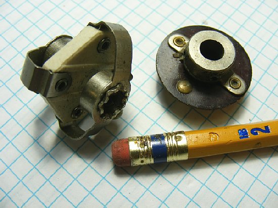
Typical 1/4 inch shaft insulated couplings.
C1 antenna input
was mounted inside the chassis and a 1/4 insulated coupling was used with
a shaft. The 1/4 inch coupling is insulated as C1 has to be insulated
from the chassis. C2 regen/gain can be mounted to the chassis but be sure
the rotor is grounded. The choke across J2 is not critical but must be
installed and is not shown on the QST schematic. I tested several
chokes between 150 uH and 2.5 mH and any value worked and performance
was not degraded so I picked the 150 uH as it was smaller.
NOTE: I used the above configuration with L1-L2 on the left and C2 on the right as I wanted the Input terminals of the left side of the chassis when the preamp was sitting on top of my model BC-221/TS-164 which has the antenna post mounted on top of the case.There are numerous versions of the BC-221 with different panel layout and antenna post locations so that may be a factor in your decision for parts placement.
Antenna input variable capacitor C1 has to be insulated from the chassis and is mounted on a bracket inside the chassis with a insulated coupling used on its shaft. Regen capacitor C2 can be mounted on the front panel and does not need to be insulated.
http://radionerds.com/index.php/BC-221
The airborne version of the BC-221 was a TS-164 which actually is a repackaged BC-221 in a light weight aluminum case with shock mounts. It was powered by the BC-348 via an external connection. Details and schematic can be found on the famous "Army Air Force Radio" site:
The TS-164 case has a 4 pin Jones connector installed on the upper side. This connector was used to obtain power from the BC-348. Sadly my TS-164 has all ready been stripped so the connector was utilized to provided power for the RF preamp.
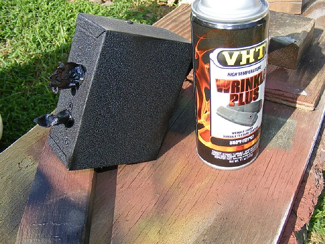
"I love the smell of black wrinkle in the morning." VHT Wrinkle Plus is available at your Auto Supply store. An excellent wrinkle paint probably the best I have ever used.
As with
any receiver using a antenna tuner to match your system will improve RF
sensitivity and help some what with selectivity. My favorite circuit is
the "Ultimate Transmatch" designed by Lew McCoy. The design
has received a lot of criticism because it uses a "split" variable
on the input but I've always been able to match with it. BTW an old trick
is if you are not sure of the load and your antenna tuner seems to be
out of range then simply reverse the input and output
and you have a whole new system to play with.
TIP: If you do not have a "split variable" capacitor when building Lew's "Transmatch" then use two separate capacitors and this will give you an extra knob to twiddle with and actually provide more precise tuning as you will be able to "tweak" each capacitor then you will feel like you are doing some real radioing especially when you get that magic SWR down to 1:1 which is usually a useless exercise. My general SWR tuning goal on HF is usually to just quite at approximately 3:1 due to low feed line loses.
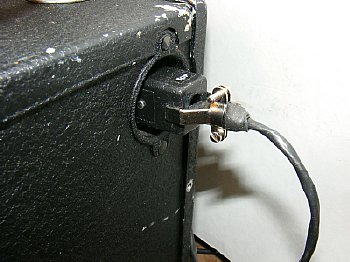
Short leads from the preamp to the input terminals of the BC-221 which in this case is a airborne version the TS-164. The 50 ohm antenna input connector (SO-239) is on mounted on the rear of the preamp. Later on when operating transceive I will mount a TR switch at the antenna input of the BC-221/TS-164.
BC-221 Receiver sensitivity testing (radios have feelings too) using different configurations:
BC-221/Regen Preamp combination
with earphones:
With very
careful adjustment of the preamp controls we were able to detect a steady
unmodulated carrier down to 10 to 20 uV. In this 10 to 20 uV area signals
were at "crystal set" audio levels.
BC-221/Regen Preamp with an
external audio amplifier and Trim Headset.
Hanging
that Rad Shack Mini amp on the output and using earphones makes the receiver
come alive. We were able to detect a carrier by ear down to the 5uV range
but it takes careful tuning and adjustment of the preamp.
BTW initial tuning of the RF preamp on an antenna is easier if you connect your signal generator to an external antenna or just use a 15 foot piece of wire and use the signal generator to send a test signal "over the air". Use the receiver on its normal antenna and initial tune the preamp using the signal generator/antenna as a signal source. On the East Coast NY VOLMET on 3.485 is a nice signal source in the evening. And as mentioned before W1AW sends various practice CW text in the evening from QST magazine at different speeds on frequency 3.5815.
Tuning tip:
The BC-221 and the RF preamp and BC-221 combo will detect both side bands
and does not automatically develop "single signal" reception.
However due to the action of the regen control on this single tube preamp
and the characteristics of the mixer/detector stage of the BC-221 one
side of the received signal may be slightly stronger than the other side.
So try each side and pick one. Play with it.
Video
Links:
BC-221 Reception of W3PWW on the MRCA Net.
Numerous net check ins can be heard.
Reception
of AJ1G on the MRCA Net.
WW2LST
on the MRCA net.
SSB
reception NY VOLMET