
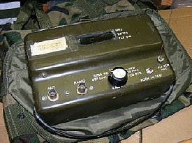
AN/PRM-34
Radio Test Set
and some notes on the BA-5847B battery.
What can I do with a PRM-34?
1. VHF signal generator- test receiver sensitively.
a. Test squelch circuits old and "new".
b. Check receiver frequency.
2. Frequency Counter - check transmitter frequency- VHF and HF
3. Forward- Reverse Power meter- can be calibrated for any band.
4.
Field Strength indicator. Usable across the VHF spectrum. No tuned circuits.
5.
Or just ignore it, leave it on the shelf.
Click
to enlarge
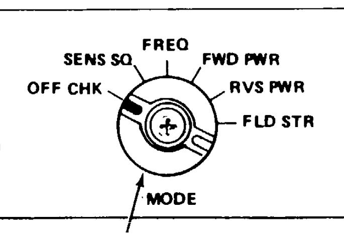
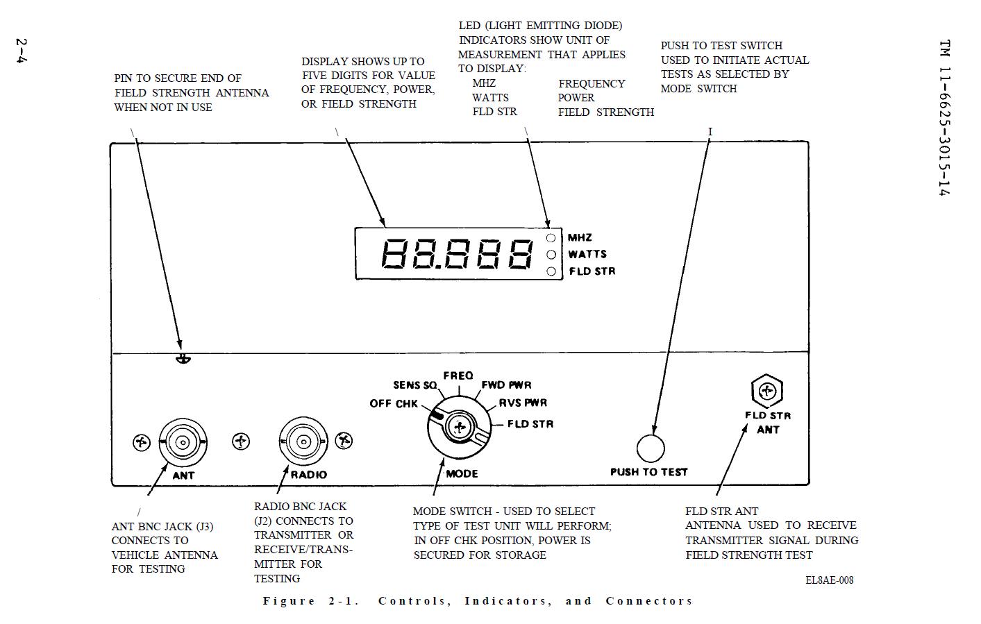
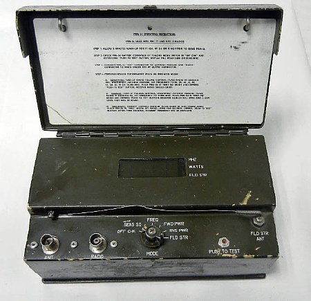
Note
in all positions the Push to Test button has to be depressed in order
a
to power the function.
OFF
CHK- allows self testing of the unit - 01000 will appear in the window
when the test button is pressed.
SENS SQ - interesting mode transmits a very lower power test signal across
the VHF spectrum every 5 Mcs. Can be use to test receiver squelch circuits
and has
a 150 cycle tone for the "new squelch". The FM carrier generated
is also modulated
with a 900 cycle tone.
FREQ-
Measures transmitter frequency when a transmitter and load are
connected. Works down through the HF bands, works with the GRC-9, RS-6
etc.
FWD
RVS PWR- Forward and reverse power from a "thru line sampler"
Maximum power around 50 watts. Can be calibrated for HF or VHF.
FLD
STR- Measure relative field strength indication. Sense antenna is
mounted on the front of the set. No calibration just relative indications.
Use to
tune PRC-6, PRC-68 for max field strength.
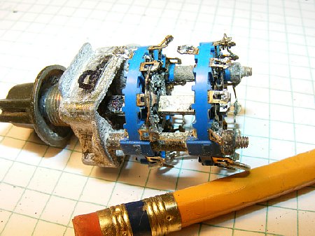
There
are probably hundreds of these PRM-34 test sets that have a bad
rotary switch as a result of leaking gases from the BA-5847 lithium battery.
The gas also attacks the plastic especially the plastic shaft pieces that
move
the wafer wipers. Nasty.
The
TM-6625-3015-14 can be down loaded from the link below. The
TM does contain trouble shooting info but no schematics or detailed wiring
diagrams. After an extensive search the schematic were found.
TM-6625-3015-14
PDF files
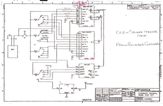
The PDF files with schematics for all of the boards thanks to Pat KC2RNN
who knows everyone.
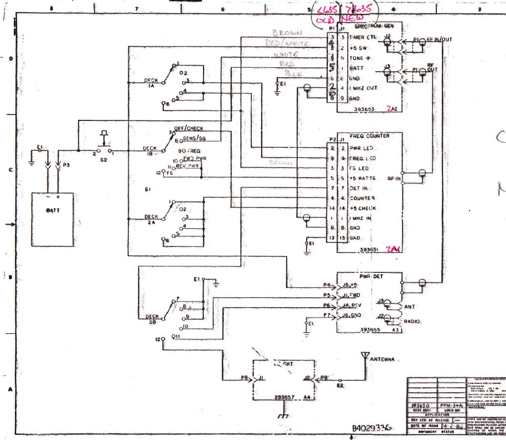
Schematic diagrams for all PRM-34 boards and chassis wiring diagram.
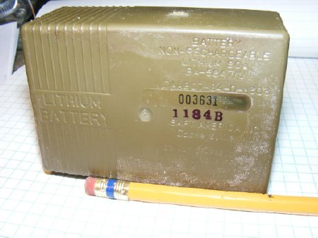
The
villain. The BA-5847B/ lithium battery which may eventually leak gas while
in extended storage.
Another government project designed to fail.
More info on the battery below.
Early model PRM-34's had a square case.
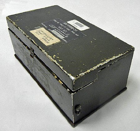
Even the storage box was square on the early model.
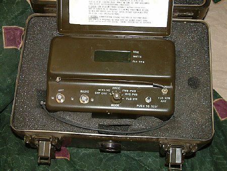
Late model set with rounded corners. This is not my set, it is too nice.
I don't have cases for any of my stuff.
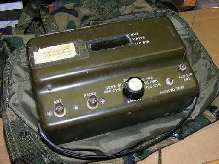
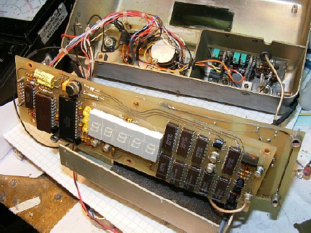
My
set. No case. No cover. No antenna. But is does work.
My ham fest special
found as I was "Hanzing" though some boxes of test equipment
at the
Tomonium hamfest and purchased for a buck. Wish I had purchased more of
the units now
but . . . No top cover and I replaced the missing antenna with a short
piece of "piano" wire and
replaced the main rotary switch and push to test switch. Piano wire available
at your hobby store.
Improvise-Adapt-Overcome.
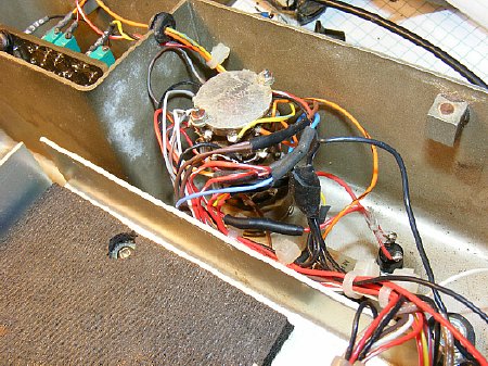
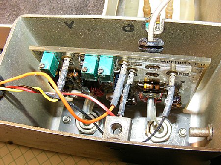
Replacement rotary function switch installed , some of the wire leads
had to be extended. Takes about 45 minutes to install another switch. The push to test switch(NO)
was also attacked by the gas and was bad.
subbed if one of the test functions is eliminated just wire up 5 leads and skip for instance Field Strength.
CLICK
The wiring diagram for the "4 pole- 6 position" rotary switch.
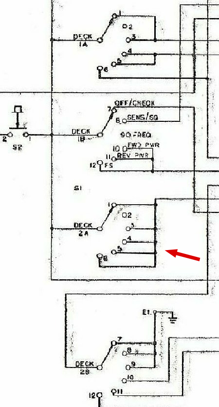
When wiring the switch put the jumpers between positions on the switch first.
In the diagram above Deck 2A has a jumper running between positions 3-4-5-6. Also make
sure you wire the wipers of Deck 1A,1B and 2A to the test switch which provides voltage.
CLICK
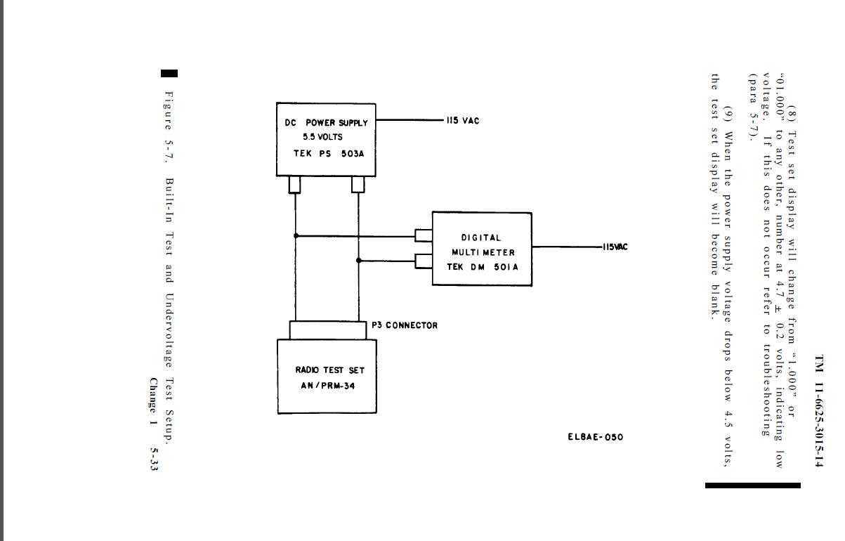
When
testing the unit the tech manual procedure is to apply 5.5 volts.
Any voltage above 6.3 causes the set to become unstable and possible damage
can occur.
The set does not have any voltage regulation. Go below 4.6 volts and the
set goes
into another time zone.
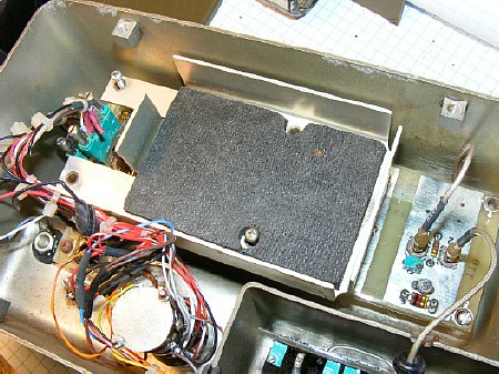
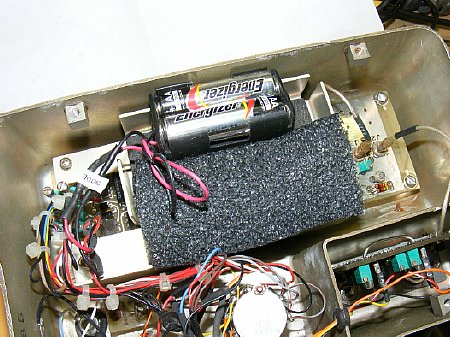
The battery tray can be removed for access to the main boards.
The
main boards have 7 and 10 pin connectors. IC's are not socketed.
The boards are doubled sided.
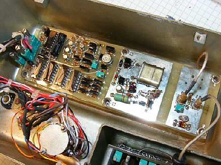
The spectrum generator board piggy backs on top of the frequency counter board.
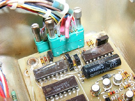
The
frequency counter board. All devices in the set are powered
by a 5 volt buss. There are no voltage regulators on the boards. Be careful
when testing.
A possible supplier of boards is Steve Haney his ebay
listing is here:
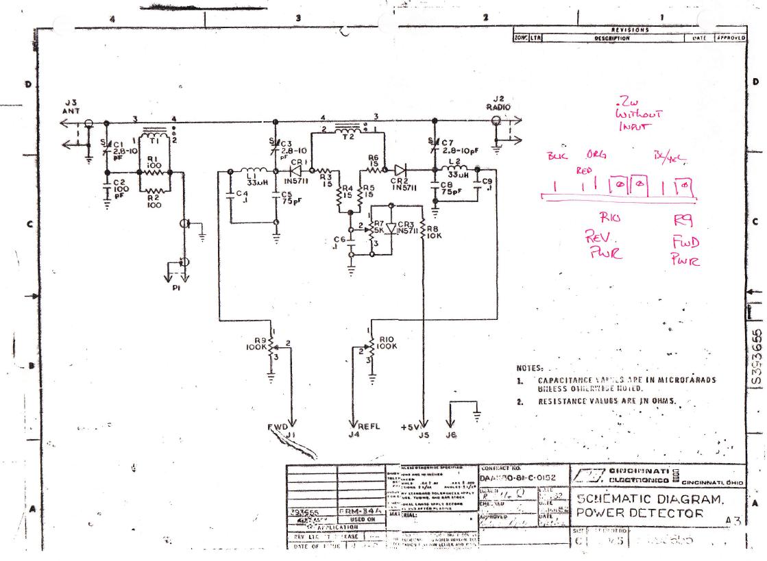
Power
detector board. Very easy to adjust and calibrate with the
three precision multi turn pots. The sampling circuit is a thru line and
is capable
of at least 50 watts of RF. The board can be calibrated for any band HF
thru VHF,
I calibrated mine for HF ops on 60 meters.
CLICK
Field Strength board schematic.
A
4 cell (6 volt) battery pack can easily fit inside the battery compartment
but a diode
must be placed in series with one of the leads to drop the pack to approximately
5.5 volts.
Wire the diode on one of the sets power leads first before testing, it
serves as a reverse voltage
protection device in the event of one of those little bench mistakes that
we all have made.
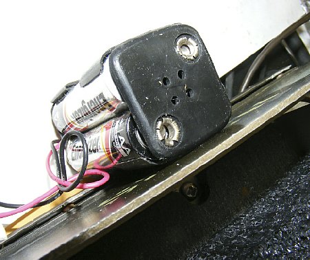
Most of the imported battery holders have exposed terminals which can be insulated
with tape.
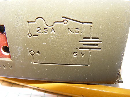
On
the BA-5847 battery there is a non resetable thermal switch ,a series
diode, and a
standard 3 amp fuse. Later model batteries has a built in resistor and
switch that could be
used to discharge the battery prior to disposal. NOT shown on the battery
housing diagram
is the voltage dropping diode.
Post-mortem dissection of the battery. Ugly.
Insulated
tubing was used to house the diode which connects to the fuse. The thermal
protection device which is in series with the diode and fuse is placed
near the batteries for
maximum heat sensing. The 3 amp fuse rests in its round tube on the right.
It is possible to
replace the fuse by using a razor saw and cutting around the edge of the
battery and lifting the
edge of the battery housing. Cut the box edge near the "NEG"
connector.
Series diode.
Its
a neat battery package but ruined a lot of equipment. They finally started
making
test equipment, night vision scopes etc. that used "real batteries".
That's
about all I know about BA-5847's and kind of sorry I got involved with
the thing.
Field
strength board. The insulated antenna connection is on the left was
completely destroyed by the gas and a fabricated replacement using flat
faucet washers
was installed. Improvise, adapt overcome.
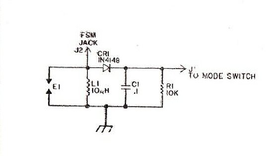
No RF input tuning circuit is provided on the field strength board.
Return to top of page