

This page contain instructions and information on converting the PRC-77 from Tone Squelch* to a Noise Squelch. Modification to the early A54 and later version A54A Tone Squelch Modules will be covered as well as off the shelf squelch boards that can be purchased and do not require modification. During the modification to the A54 and A5A boards several components will have to be removed from the boards and a couple of new components added. Time for the average mod is 1 hour. I suggest that you read all of this presentation before making a decision.
* Tone squelch
or "New Squelch" also know as PL, Channel Guard etc. required
a subaudible tone to be superimposed on the transmitter carrier at a frequency
of 150 cycles at approximately 3 Kc deviation. A really stupid idea designed
by contractors and engineers to sell radios. One theory is that the "enemy"
could not jam or interfere while using the New Squelch system. The adoption
of New Squelch by NATO left half the world on Old Squelch and the the
other half on New Squelch. Operational plans had to be written to accomodate
both squelch systems. The new Squelch idea is just about as stupid as
the Vietnam war of which I served a one year tour and spent another 6
several years of my life providing combat airlift support.
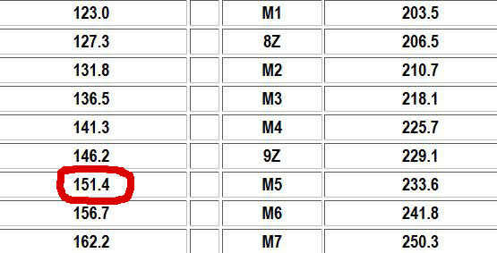
The 150 cycle
tone was nonstandard and the closest commercial tone was 151.4. If you
converted a military wide band FM radio to tone and used the 151.4 tone
the radio will work most of the time with other "New Squelch"
radios depending on the alignment of your tone module and the strength
of the signal - usually for Military Rallies, Hamfests, short convoys
the use of 151.4 tone was adequate but for long range Comm where the received
signal was down in the uV range the tone would often not activate. But
the purpose of this page is to convert the PRC-77 to "noise"
squelch and make the PRC-77 usable with any type of wide band FM radio.
.
NOTE:
The modification of the PRC-77 Tone Squelch Module does not effect transmission
it only effects reception. You will still transmit the 150 cycle tone.
Additional Info by Craig N3TPM. "150hz is a standard tone used in the broadcast industry most notably for triggering start/stop on cart machines and on some early cassette based answering machines." N3TPM
FT-243
crystal shown for size comparision.
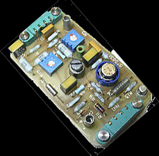
Several "conversion"boards
were manufactured that were capable of 150 cycle tone because they were
tunable over a continious range. One of my favorites was the Selectone
ST-140 due to its small size. Note the Multi turn pot on the board. On
the right is a another board that has dip switches to program the codes
using a divider chain and a crystal oscillator and no matter what combination
of switches you could not program a 150 cycle tone. Others have modified
these boards by changing the crystal on the dip switch boards but why
bother? In general the smaller boards were for transmit only and the larger
boards offered transmit encoding and receive decoding.
I got tired of not
having New Squelch at rallies and meets so converted my FSE 38/58 radio
to transmit the tone.
http://k4che.com/FSE/FSE%2038%20PL%20page1.htm
 Try and read all the info present here before making a decision.
 Index
and page links to PRC-77 Noise Squelch Methods Covered on this Page.
1.
Commercial Boards (first section) New W3KKC Board added.
2
Modifying the original early A54 Squelch Tone module.
3.
Modifying the later model A54A Squelch Tone Module.
Please
Note: My PRC-77 Noise Squelch "Beta" testing consisted of installing
one commercial board (W3KKC) and modifying several A54 and A54A Tone Squelch
modules. I would like to hear from anyone that converts his PRC-77 to
noise squelch.
73
k4che
email: K4CHE at American Radio Relay League (ARRL).Net
Regardless of the squelch circuit that is chosen the circuit needs to be capable of keying the "Squelch Relay" this is good news as a direct switching circuit of the audio can be difficult and to be done properly the switching often has to often occur early in the audio chain.
One side of the K3 relay coil is powered by the radio's 10 volt regulated buss and when a ground is applied to the other side of the coil the relay closes. Current draw of the relay coil is important and in this case it is approximately 5-7 mA. Note the two sets on contacts on the relay. One set of contact is used to switch the audio the other set is used for transmitter keying when two PRC-77's are used for retransmission. The Squelch Relay system is the same in the PRC-25.
K3 the Squelch Relay is located on the top of the radio near the antenna BNC. It is easily replaced in the event of failure but I have never experienced a bad relay. The same relay is used on the PRC-25. On the bench during relay operations you an actually hear the relay click as it closes.

Remember you must be in SQUELCH or RETRANS to provide power to J2 the Tone Squelch Board connector. The radio functions are the same in either mode. In the ON mode the squelch board is bypassed and the squelch relay is activated.
A
discussion on the -35 (dash 35) manual for the PRC-77.
Looking
for schematics of the A54 and A54A modules? Good luck.
The schematics were only
available with the original manual. But later "some" of the
reprints of the manual that "incorporated" Changes 1 through
3 also had the schematics. Why? I have no idea. Now if you are looking
for a schematic of the original A54 Tone Module good luck with that. If
you run across a change two only manual you might find a schematic for
the later model module the A54A. Some original manuals have the schematic
for the A54A module listed on the "Module Reference Diagrams"
page as Figure 7-22 but in the same manual it is not there. Best advice
is look for the first edition of the manual without any changes or a manual
with just Change 1. FUBAR*
Anyone that has a PDF file of the complete manual with all module schematics and with at least a schematic of one of the tone modules let me know and I will post it here.
Anyway you will find schematic for both early and late model tone modules on these pages.
*FUBAR- And old military term especially popular in Vietnam.

Older
W3KKC board shown - see below for the new W3KKC board info.
W3KKC
has developed a squelch board available assembled or as a kit. The
board utilizes a Motorola Micor IC that is not available from any distributor
but W3KKC has obviously collected a large supply. Price for the kit is
$50 which includes the IC. The squelch sensitivity is controlled by a
on board pot mounted on the board. Assembled and tested the board is $75.
New info below
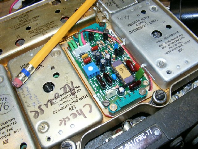
In
the photo above I have taken a older PRC-77 module board that was inop
and had parts missing etc. Since the board has several defects it became
a mount for the W3KKC board.
IMPORTANT UPDATE:
W3KKC has changed the design of his squelch board. SEE BELOW

NEW
BOARD
W3KKC photo. Model MS-50 squelch
The new W3KKC board (Model MS-50)
is complete and does not require any "outside" components. The
board can be built from a kit or ordered assembled.
When
ordered as a kit or assembled the surface mount IC's are all ready installed.
W3KKC
Link:
https://masterscommunications.com/products/squelch/ms50.html
W3KKC MS-50 board features


MS-50
Schematic -CLICK to enlarge
PRC-77
Connections for the W3KKC squelch board. : Pin 1 Ground, Pin 2 audio in,
pin 4 to squelch relay, Pin 5 is the power supply supply input.
The W3KKC schematic indicates a input
voltage supply of +12 to 16 VDC. The minimum
of 12 volts was needed in order to use the on board regulator . In the
past I have gotten away with using the PRC-77 regulated 10 volts for power
and forcing it through the SM-50 regulator(9 volt) circuit. But a better
solution is when building the kit or ordering assembled just omit or bypass
the SM-50 9 volt regulator.
https://masterscommunications.com/products/squelch/ms50_docs.html
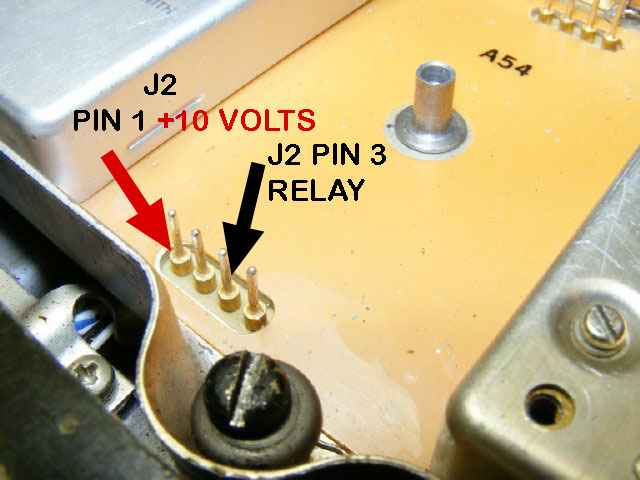
Bench Lab Experiment 101. Turn on the set, select SQUELCH and check for power on the J2 connector pin 1. Remember that J2 is the connector nearest the front of the radio. Try grounding pin 3 to activate the Squelch relay. The squelch relay draws 5-7 Ma. You should be able to hear the relay close and hear audio. When pin 3 is not grounded you should measure approximately 9 volts on the pin.
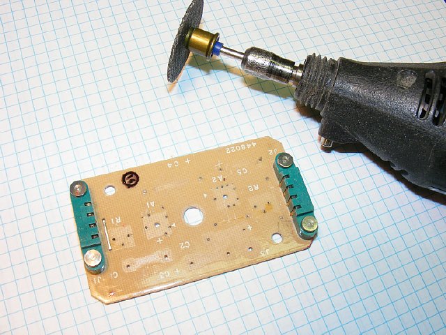
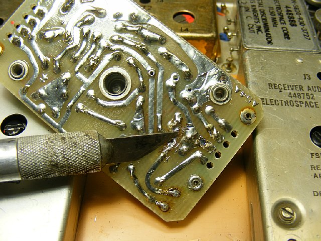
Using
my favorite tool the Dremel with a "cut off" disk I cleaned
up a old inop defunct "donor board" and used it for mounting
the W3KKC squelch board. Other inop
module boards could also be used as long as the pin out is the same.
Steve Haney Electronics might be able to help you out with your module board needs.
https://haneyelectronic-com.3dcartstores.com/
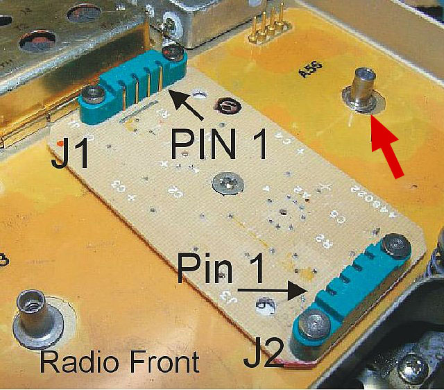
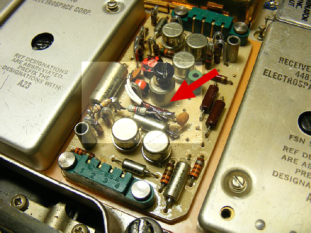
Note that J2 is near the front of the radio and J1 is near the rear. Part of a module hold down insert (red arrow) had to be filed down to make room for the assembly. Each connector has the pin numbers stamped on the housing. Each connector has the J number on the board.

Older board shown for information only.
INFO ONLY: The older W3KKC board is mounted with small tap screws to the "donor" board.Wires had to be soldered to the W3KKC connector in order to save space. Pins 1 and 2 (ground and audio in) are connected to the rear connector J1 via short wires underneath the board. Pins 4 and 5(relay control and 10 volt power) are connected to J2 via brown and red wires that run the length of the board. .
Q.
Does modifying the squelch effect transmitting the 150 cycle tone.
A.
No you still transmit the "New Squelch" tone.
Q.
How do you get the cover back on the module with the W3KKC module installed.
A.
You don't. That is the bad news.
Q.
What is the squelch sensitivity of the W3KKC board?
A.
1 to 2 uV.
Q.
I see by the photo that there are several capacitors that seem to be physically
higher than the other components on the W3KKC board - in other words they
stick up above everything else. Will they clear the case when you put
the radio in?
A.
Yes but be careful.
Q.
Do you attend radio therapy sessions?
A.
No but I know several MRCA members that probably are in need of several
sessions.
Q.
Will you modify a board for me?
A.
NO I would rather not. The mods are not that difficult. However if you
run across my Wake Island QSL with K4CHE/KW6 on it and send it to me I
will send you a modified module.
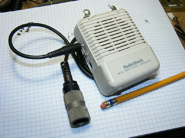
A handy piece of test equipment for mil radio audio work. Also used at rallies for demo of military radios.
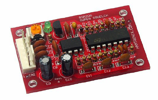
SSM200
may not be available anymore on ePay.
Another commercial
squelch board that is available but I have not tested is the Hamtronix-SSM200.
A slightly smaller board but looking at the Caps C9 and C10 located in
the front it looks like the module cover still will not fit.
Listed
on Ebay, do a search for Super Squelch. Listed for $49 with $23 shipping
from Brazil.
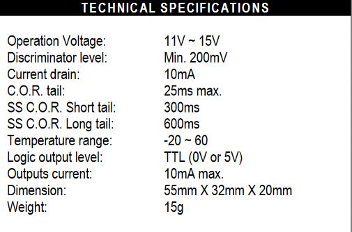
SSM200
Specifications, note the smaller size of the board.
A special thanks to
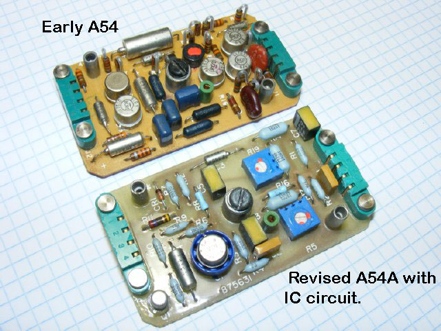
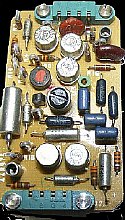
There
were two versions of the A54 board. The original version shown above was
all transistors while the later version had a integrated circuit and a
lower parts count. Searching through the manuals for a parts layout is
not necessary as parts layout pages were not published. The parts are
clearly marked on the boards.
Modification
to the original board A54 (all transistors) will be covered in this section.
Modification to the later board A54A will be covered in the next section.
CLICK to enlarge
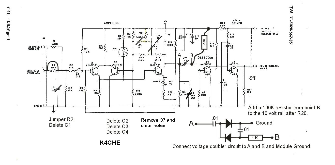
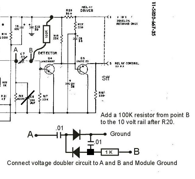
The original A54 schematic with the K4CHE noise squelch modifications. Basically you are jumping a resistor on the input, clipping out a few caps to enhance audio, inserting a voltage doubling circuit to rectify the noise voltage and adding a 100K bias resistor to Q4 . The voltage doubler rectifies the noise and applies a minus bias voltage to Q4. When there is a large reduction of noise caused by a carrier on the frequency then the minus bias voltage is reduced and then the positive bias provided by the new 100K resistor takes over and Q4 keys Q5 which in turn grounds the squelch relay.
| CAUTION: Make sure your tone board is operational prior to any modification. |
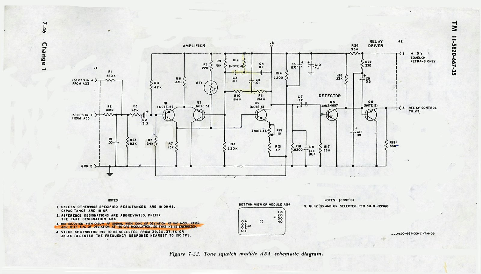
CLICK to enlarge
The original A54 Tone Squelch Module schematic often found in a Change 1 manual.
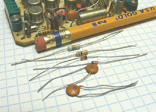
Parts needed for the K4CHE modification of the Early Tone Squelch board
A54.
1K
resistor
100
K resistor
1N914
or similar diodes (2)
.01
caps(2)
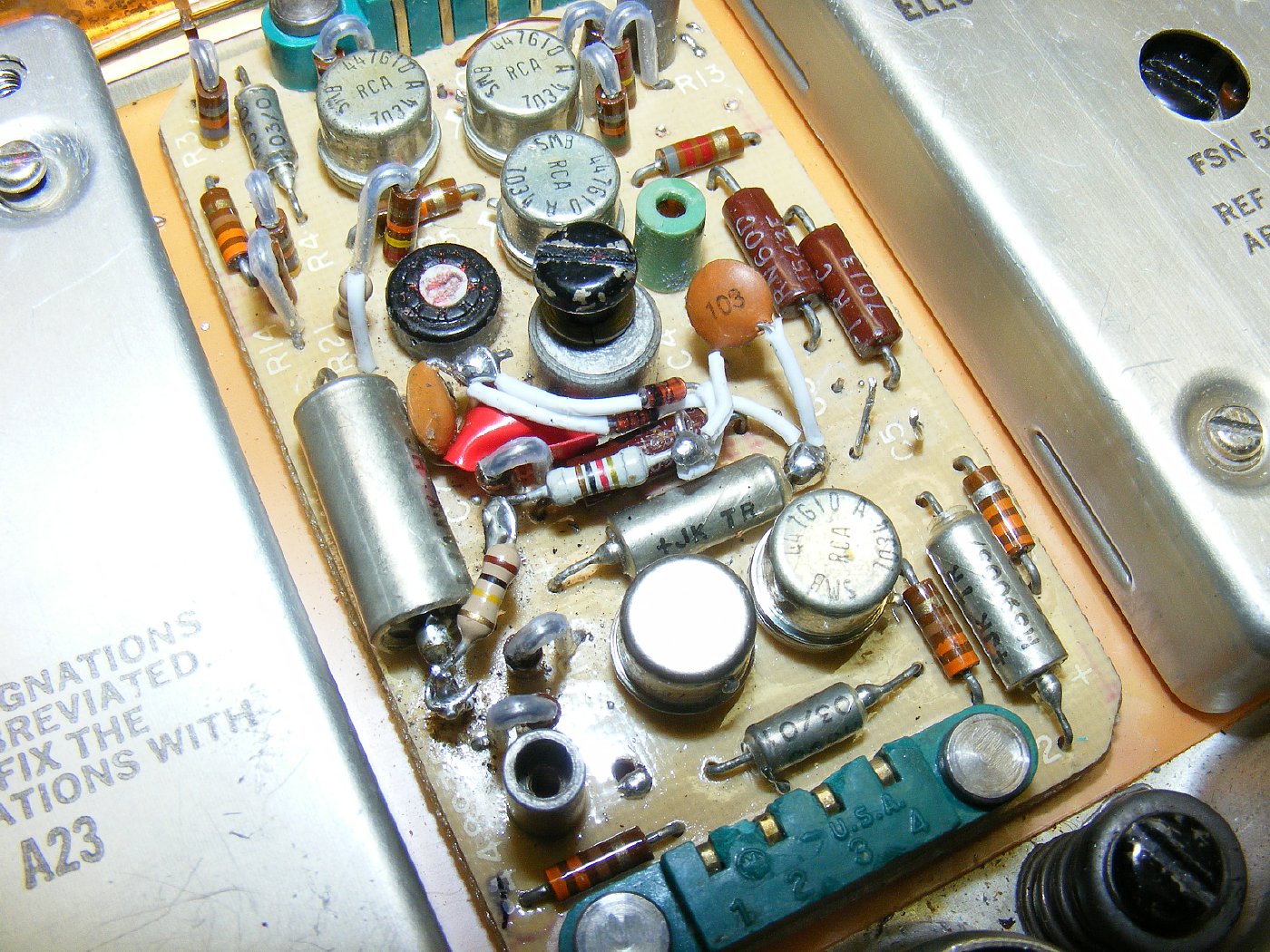
K4CHE
A Preview: The finished mod is shown above - - - the mod requires you to remove a few caps and add a couple of parts and you are done. More details below.
CLICK to enlarge
A Preview. You are going to clip out caps, jumper a resistor, and add a diode voltage doubler. In additon the bias will be changed on Q4 with a 100K resistor. The modification should take about an hour to do you can do it while checking into one of the MRCA nets while everyone else is taking their turn.

INFO ONLY this is not the actual modification.
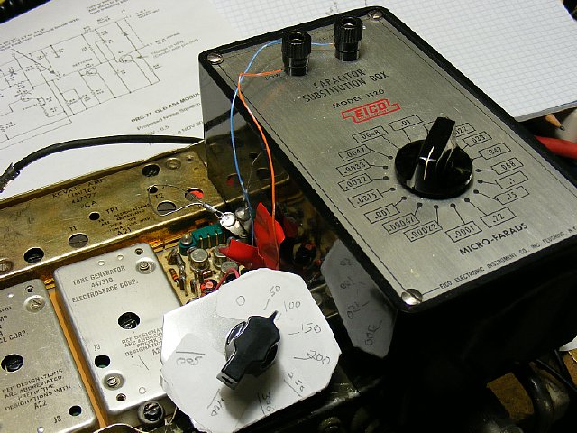
INFO ONLY: Half the fun when doing a mod is breadboarding - - a term used in early radio when you would steal a wooden breadboard from the kitchen and mount components on it. I like to use a piece of plain printed circuit board with squares cut in it with a Dremel tool for temporary mounting of components. A level pot was tried on the tone module input but was not utilized in the final circuit as there was no advantage either in sensitivity or simplicity of the mod. KISS
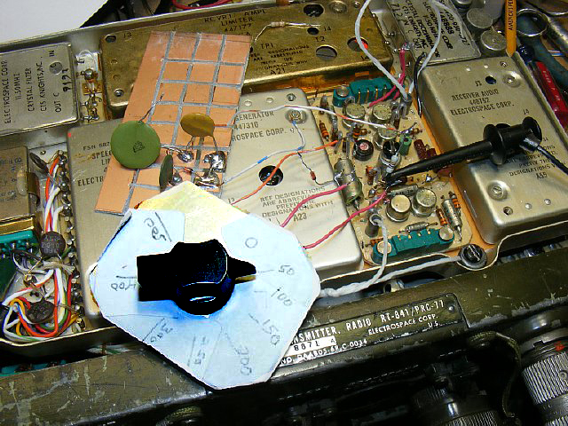
INFO ONLY: Testing for the value of the correct base bias resistor for Q4 was done with a 500K pot. Resistance values are marked on the scale and noted during testing along with voltages.

When removing components you can just clip them out and trim the leads on the board. Don't be bashful take your dykes and cut the body of the capacitor in half and then trim the leads flush with the board. WEAR SAFETY GOOGLEs when clipping.
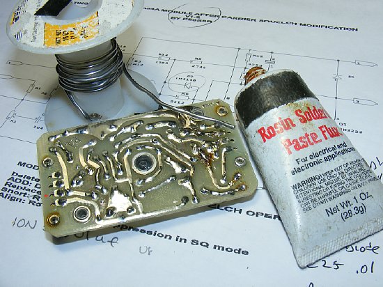
A tip: Most of the new solder is not any good. Try adding a little rosin paste to the end of your solder.
The cover when installed provides an attachment point for the "pull" knobs "Easy on easy off".
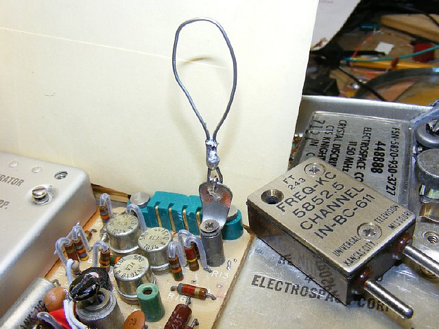
TIP: When the cover is not installed the module board is hard to remove once it has been seated on the radio chassis. Pull rings can be fabricated from solder tabs and 2-40 screws salvaged from a FT-243 crystal holder. You can put the screws back in the FT-243 after the mod or just let them get lost on your work bench. Q - When you place 4 screws on a work bench and return the next day one of the screws is always missing - What happens to the missing screw where does it go?
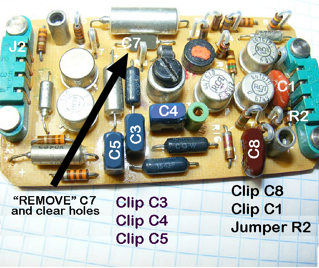
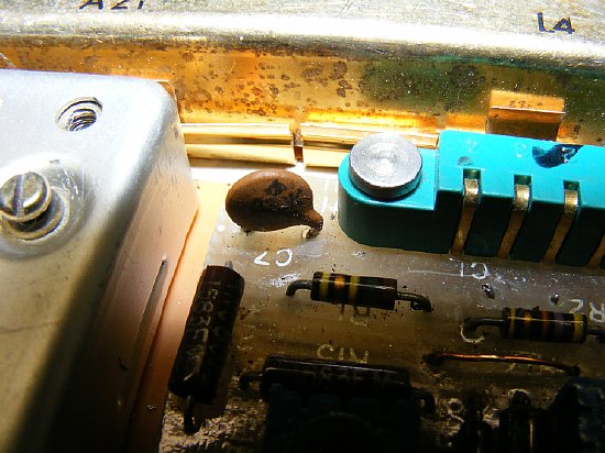
I usually clip all component bodies in half and remove portions and then trim the leads flush with the board. In the case of R2 you will remove the resistor and install a short jumper. Or if you are lazy just solder a jumper across R2 on the bottom of the board. Clip C7 and remove the leads leaving open holes - - -later you will install a short piece of wire in one of the C7 holes to serve as a soldering point and in the other hole a .01 cap. More info on the C7 area below.
TIP: And old trick - to locate the solder lands for a component on the opposite side of a board just hold it up to a bright light.
INFO ONLY: Using small diagonal cutters or dykes C3 and C4 have been removed and the leads trimmed. Other caps that will be removed are still on the board. Don't like clipping the components? Does destroying the capacitors keep you awake at night? Then take a lot of time and unsolder and remove. But - - - - every time you heat up one of the larger solder lands with multiple connections you are setting your self up for failure. Most of the components have leads that are bent over under the board which is nice rugged construction but very hard to remove components.
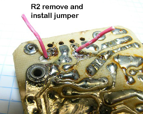
R2 can be difficult to remove as the leads might be bent over. I marked the unsolder area above and the holes that R2 utilized. Put your jumper for R2 on the other side of the board. Or just leave R2 on the board and jumper underneath.
Another tip when soldering these boards is the printed circuit lands are covered with a protective covering - so scrape off a portion of the mask in order to find a good spot for applying the soldering iron. SCRAPE before soldering.
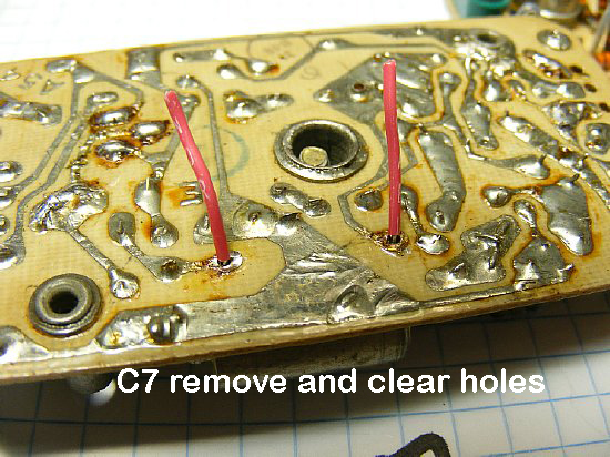
C7 you can remove intact or the easiest way is to clip the capacitor body in half and then remove the leads. Clear the holes.

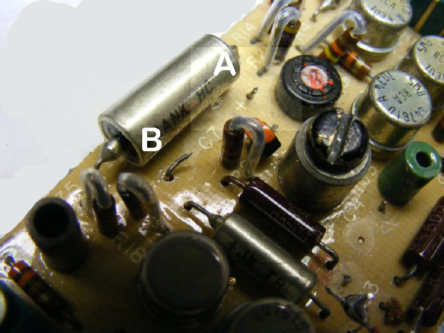
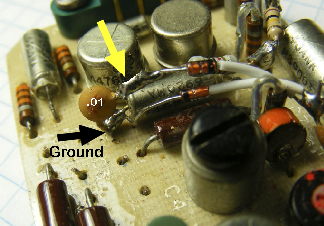
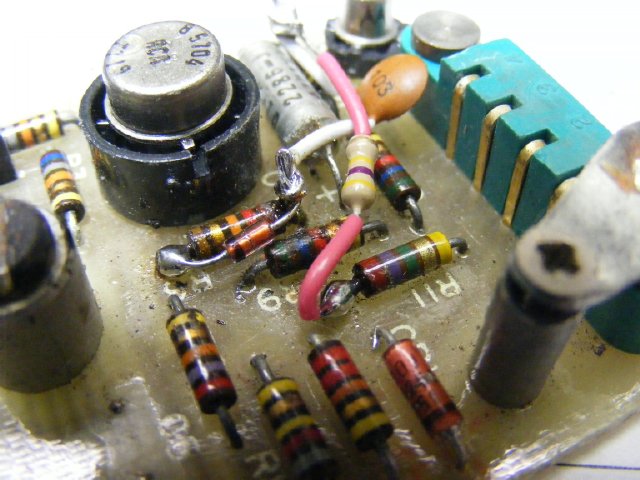
The
C7 coupling capacitor (a 2.2 uF) installation was polarized and the Plus
sign is marked on the board RED Arrow. The
+ plus side wiring goes to the collector
of Q3 and the minus side goes to the base of Q4. The +
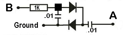
side is going to be point A on the modification schematic below
and the minus side is going to be Point B. ONE
lead of a .01 capacitor is going to be installed in the
+ side hole (Point A below) and then the other lead of this
capacitor remains vertical on the board and is going to be a solder
point for two small 1N914 diodes used for a voltage doubler.
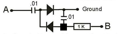
Two
diodes will be connected to the .01 capacitor that has one lead inserted
in the hole (A) left by removing C-7.
The junction marked with the BLACK square will be a point
where the lower diode anode, one end of the .01 cap and one end of the
1K resistor are soldered together to form a single connection above the
board.
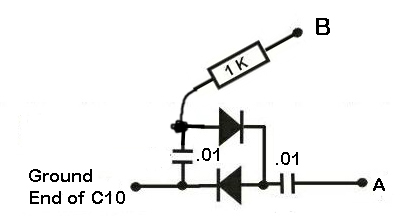
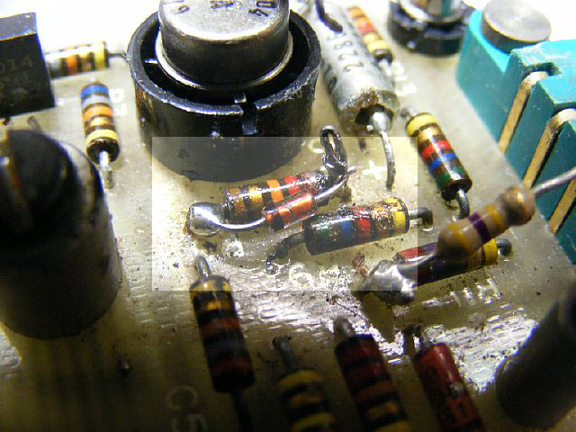
Another view and description of the C7 area modification. The body of the C7 capacitor has been clipped and removed. One lead of a new .01 capacitor will be inserted in the + area (point A) with the other lead of the capacitor will remaining vertical and used for a connection point for the two diodes. Insert a short piece of wire into hole B and this will be contact point B as show on the modification schematic. Use the smallest .01 capacitors you can find.
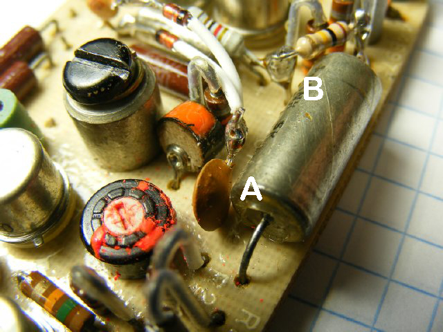
Another view of the C7 area. One lead of the .01 cap has been soldered in the hole A and the .01 capacitor is all most flush with the board and the other end is vertical where the two diodes with the leads insulated have been soldered. Hole B will have a short wire inserted and it will serve as a solder point. The ground is going to be on the ground side of C10.

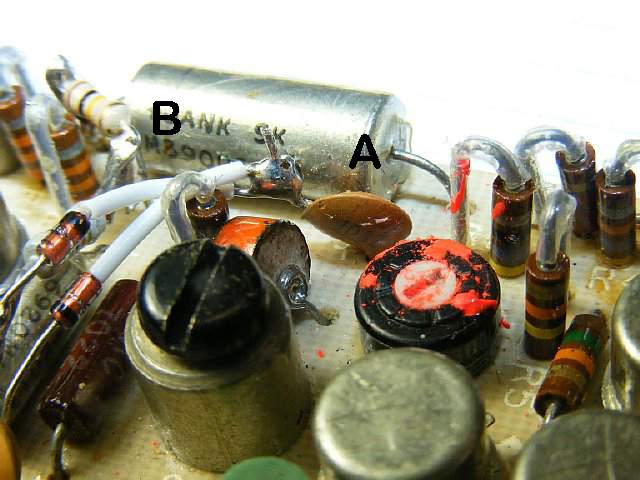
Another view of the C7(C 7 removed) area with the two diodes with leads insulated connected to a .01 capacitor inserted into hole A.
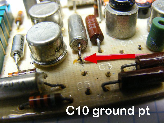
A convenient ground point is the ground side of C10. You can tin the this lead of the capacitor and solder the ground for the cathode of the diode and one lead of the .01 cap.
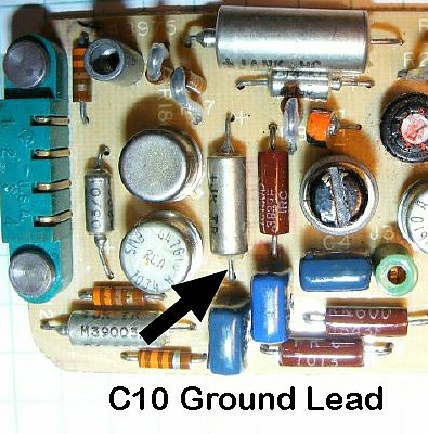
Use the end lead of C10 as a ground point.
| Another
view of the ground connection to one lead of C10. . The only leads going
to this C10 lead ground are the diode cathode and the .01 cap. The other
end of the cap (yellow arrow above)is connected to the anode of the other
diode and one lead of a 1K resistor. The 1K resistor will be connected
to Point B. Confused yet?
Cathode and one lead of the .01 cap are connected to the ground
end of C10.
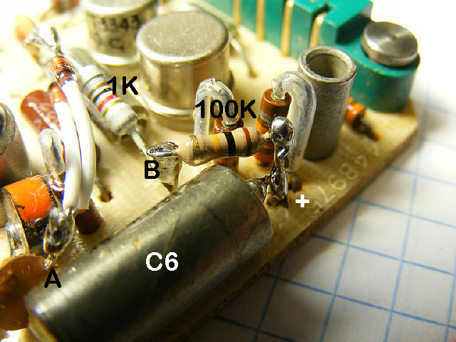
The other end of the 1K resistor and one end of the 100K bias resistor are soldered to point B. The other end of the 100K bias resistor is connected to the + side of C6 for power. A small wire was soldere3d to the end of C6 to provide a solder post. More info below.
The 100K bias resistor for the base of Q4 receives its power from the +10 volt buss. The 1K resistor from the diode pack is also soldered to point B. The voltage doubler will provide bias voltage via the 1K resistor to the base of Q4. Adjusting the fixed bias resistor whih in this case is 100K will change the squelch sensitivity. A lower value makes the squelch more sensitive. But as you approach the open squelch point the squelch "tail" in increase. 100K was chosen after doing several boards.
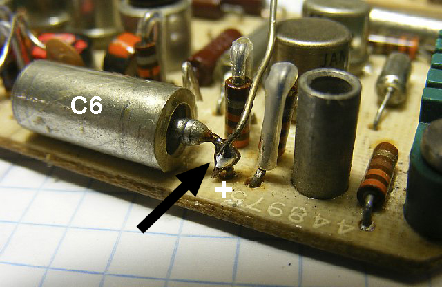
Solder a short piece of wire to the C6 positive end that is connected to the 10 regulated buss. This connection will be a source of voltage for the 100K bias resistor.
CLICK to enlarge
A view of one of the first finished boards. A little red tape used for insulation.
CLICK
to enlarge
Test
voltage Info: DC and Peak to Peak (PP).
Note:
Measure except where noted with just the receiver in Squelch and no carrier
present.
(R2 input at Jumper) No carrier present noise level of 1.5 to 2.0 volt
PP.
(J3 test point) 6 volts PP noise which varies with R15 no carrier. DC voltage is approx 4 volts.
(Point
A on Voltage doubler prior to .01 cap) 4 volts PP which is the noise
signal.
(Voltage doubler just prior to the 1 K resistor) With no signal
on the receiver antenna input expect approximately to measure -1
(minus 1 volt) volts DC. With a strong signal input of 2 uV which should
open the squelch expect to measure +.5 volts.
This is a voltage change from a minus 1 volt to a positive .5 volts. Squelch
should open at approximately zero volts.
(Pin
3 relay). Approx 9 volts DC which goes to zero when relay coil is activated
by squelch.
INFO ONLY: During testing I looked at the audio filter (schematic below) C3 and C4 were removed and expermental values were inserted for C5 in order to gain additonal noise amplifications. A value between 200 and 400 pF resulted in a slight increase in noise to the input of the voltage doubler but not enough to warrant inserting another value for C5 - so C5 was eliminated along with C3 and C4. During testing with this A54A mod I did notice that when there were very weak signals (less than .5 uV) the squelch might open on voice peaks. I am sure that increasing the parts count and complexity of the mod could eliminatge this. However any signal above 1 uv provided a good reliable squelch action. When I was working on FAA voice circuits the ground receivers were set at 5 uV- this mod works well at input down to 1 uV.
The modified early A54 module installed. Note the 1/4 inch hole that was drilled in the cover to adjust the squelch or to help let all the magic smoke out. Squelch sensitivity range is approximately 1 to 3 uV. CCW increase the sensitivity and CW decreases the sensitivity. Do not expect to hear a complete release of the squelch with the resulting white noise. In most cases just leave the pot CCW. A greater operating range could have been achieved at the expense of replacing R15 and increasing the parts count for the modification.
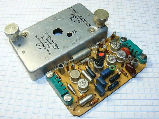
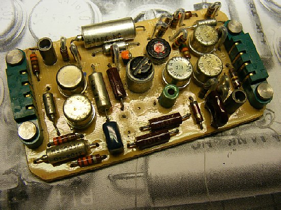
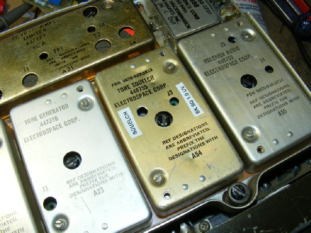
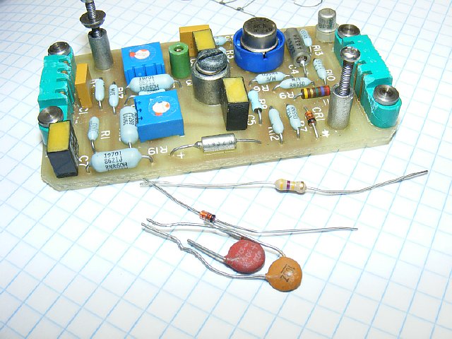
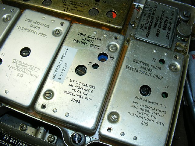
Upper board is an early or original A54, the lower board is a later A54A board which will be modified in this section.
There were two versions of the A54 board. The early version shown above was all transistors while the later version had a integrated circuit and a lower parts count. Searching through the manuals for a parts layout is not necessary as parts layout pages were not published. The parts are clearly marked on the boards.
| CAUTION: Make sure your tone board is operational prior to any modification. |
The modification by
I will try with a few photos to help with the modification on this page and a PDF file by
Click here to download the PDF file for the A54A mod.
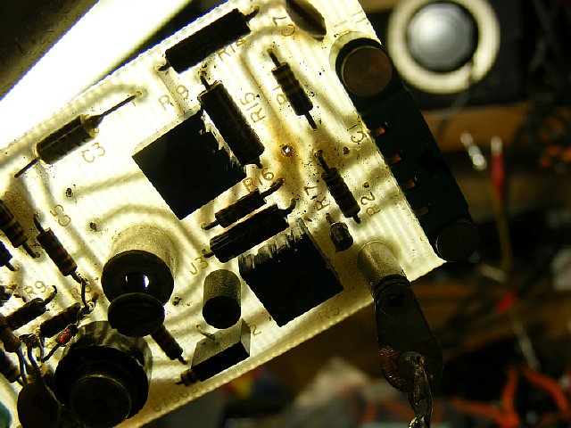
TIP: A old trick from the early printed circuit board days - to locate the solder lands on the opposite side of a board, hold it up to a bright light. In this case I am trying to locate the solder points for R17 as I plan to remove it and install a jumper in its place as per the modification instructions.
Another tip when soldering these PRC-77 module boards, the lands are covered with a sort of protective covering - so scrape off a portion of the mask in order to find a good spot for applying the soldering iron. SCRAPE before soldering.
Another tip: Most of the new solder is not any good. Try adding a little rosin paste to the end of your solder.
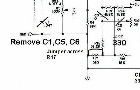
CLICK to enlarge.
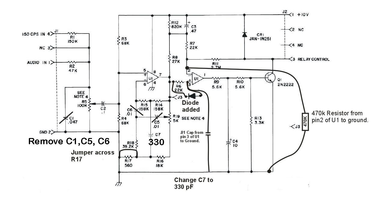
I prefer showing the original schematic with the circuit changes. Note the polarity of the Added Diode required by the mod which provides a minus bias to one of the inputs of U1. By deleting various caps you are improving the overall audio response as we are no longer interest in a narrow pass band filter.
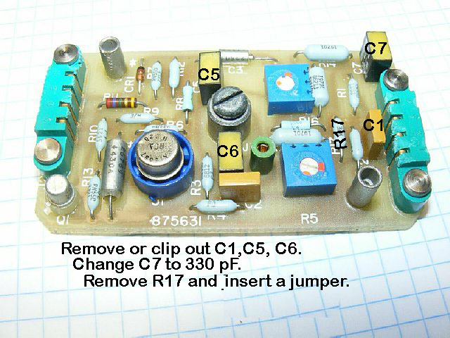
Remove R17 and insert a short jumper wire. Or solder a jumper underneath the board.
Change C7 located near connector J1 to a new value of 330 pF.
Solder
a diode across the R6 (a 22K resistor ). Note the location of the cathode
(black stripe) on the diode. I made a small soldering post out of a piece
of scrap wire and attached it to the end of the resistor R6 for soldering
a additional capacitor. This wire "post"is attached to the opposite
side of the resistor from the cathode of the diode.
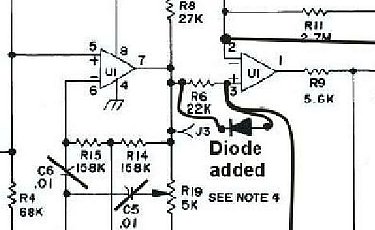
Diode
across R6.
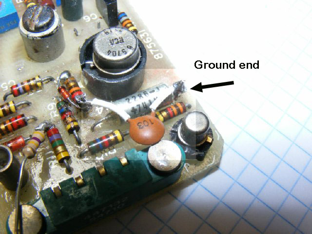
A .01 (103) capacitor is soldered to the diode anode/R6 connection where
you installed the wire "post" and the other end of the cap is
soldered to a convenient ground point which in this case is the ground
end connection for capacitor C4. Strip some insulation off of a small
diameter wire and use it for spaghetti sleeve insulation for the capacitor
leads.

A
470K resistor is soldered to the end of R11(2.7M) which is a convenient
tie point for pin 2 of the IC. The other end of the 470K resistor is
also grounded to the ground side of C4. So now you have the .01 cap
lead and the 470K lead attached to the end of C4 for ground. Insulate
the leads.
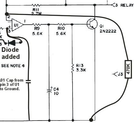
470K
resistor added from the end of R11 to ground.
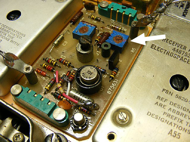
R5
is now the Squelch Adjustment. Adjust CCW to "Open the squelch and
CW to "Tighten" the squelch.
Sensitivity tests conducted on two modules resulted in a squelch range
of .3 to .5 uV. Thank you ![]() .
.
Installed A54A module , the access hole for adjusting R5 was all ready in the cover so it was not necessary to drill a hole.

When choosing a squelch circuit for the PRC-77 keep in mind that the actual audio is switched by the Squelch Relay. All you need for the PRC-77 is a closing or a Low signal for the relay circuit.
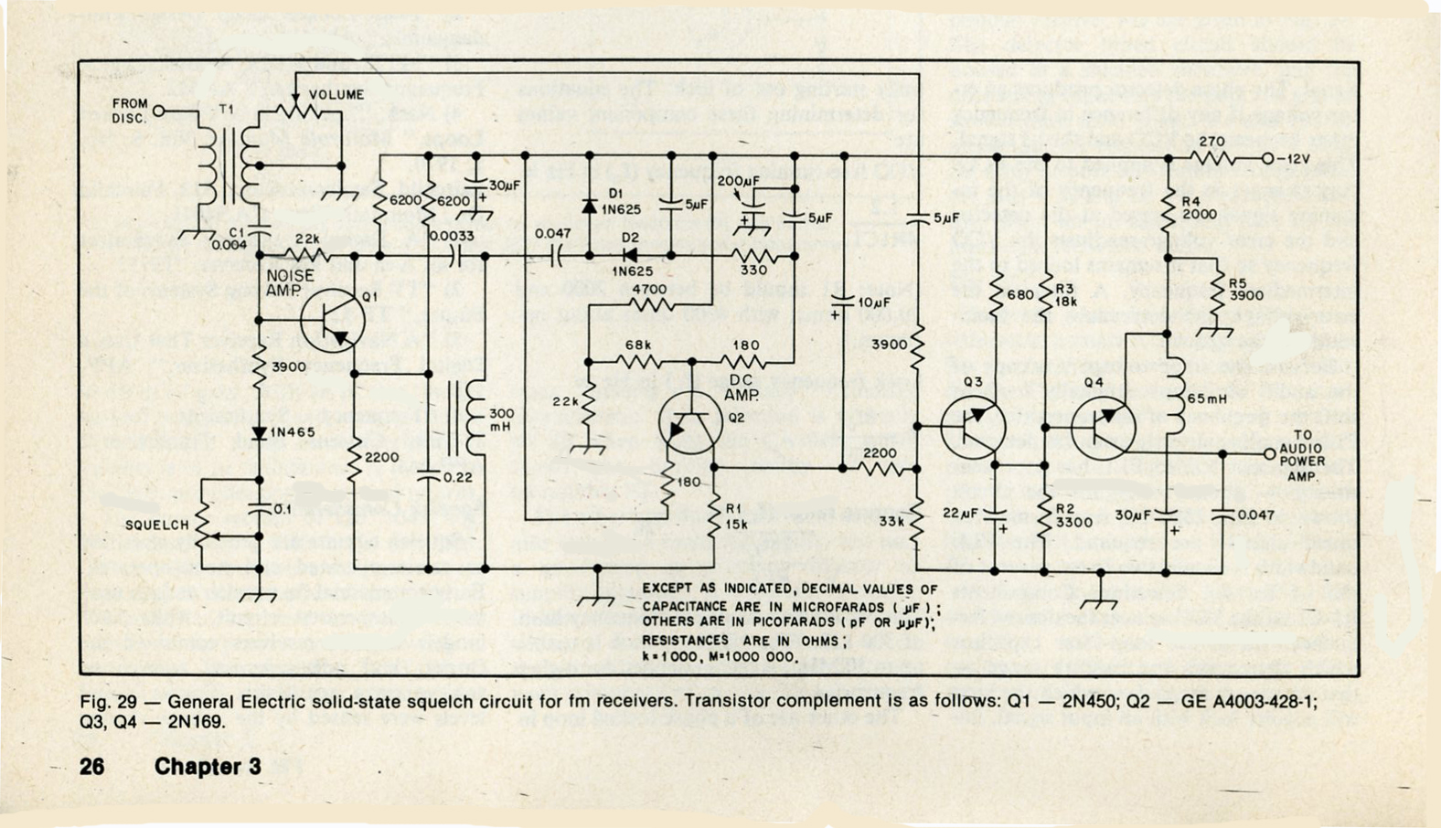
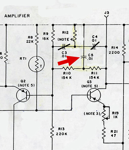
ARRL FM & Repeaters Handbook, page 26.
General Electric squelch circuit in their early transistoried commercial radios. Note the voltage doubler for noise which is where I got my idea to use one when modifying the A54 early orginial PRC-77 Tone Squelch module.
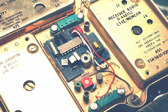
Year ago I sent Al, N3FRQ a MICOR squelch board when he was working on a PRC-77 noise squelch. He pulled the IC from the board and devised a circuit that fits the standard module board used on the PRC-77. Neat but the bad news is the M6709 MICOR chip can not be purchased and the squelch board must be salvaged from a Micor radio.
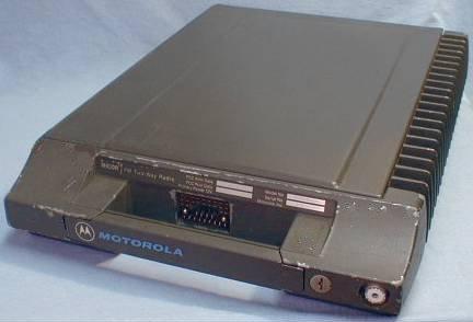
Photo courtesy Repeater Builder.Com
The MICOR was a hefty 100 watt radio and was built in several different frequency versions.
As far as I know the squelch board was standard in all the radios. Hamfest purchase $10 or wait till the hamfest is over and look in the trash barrels.
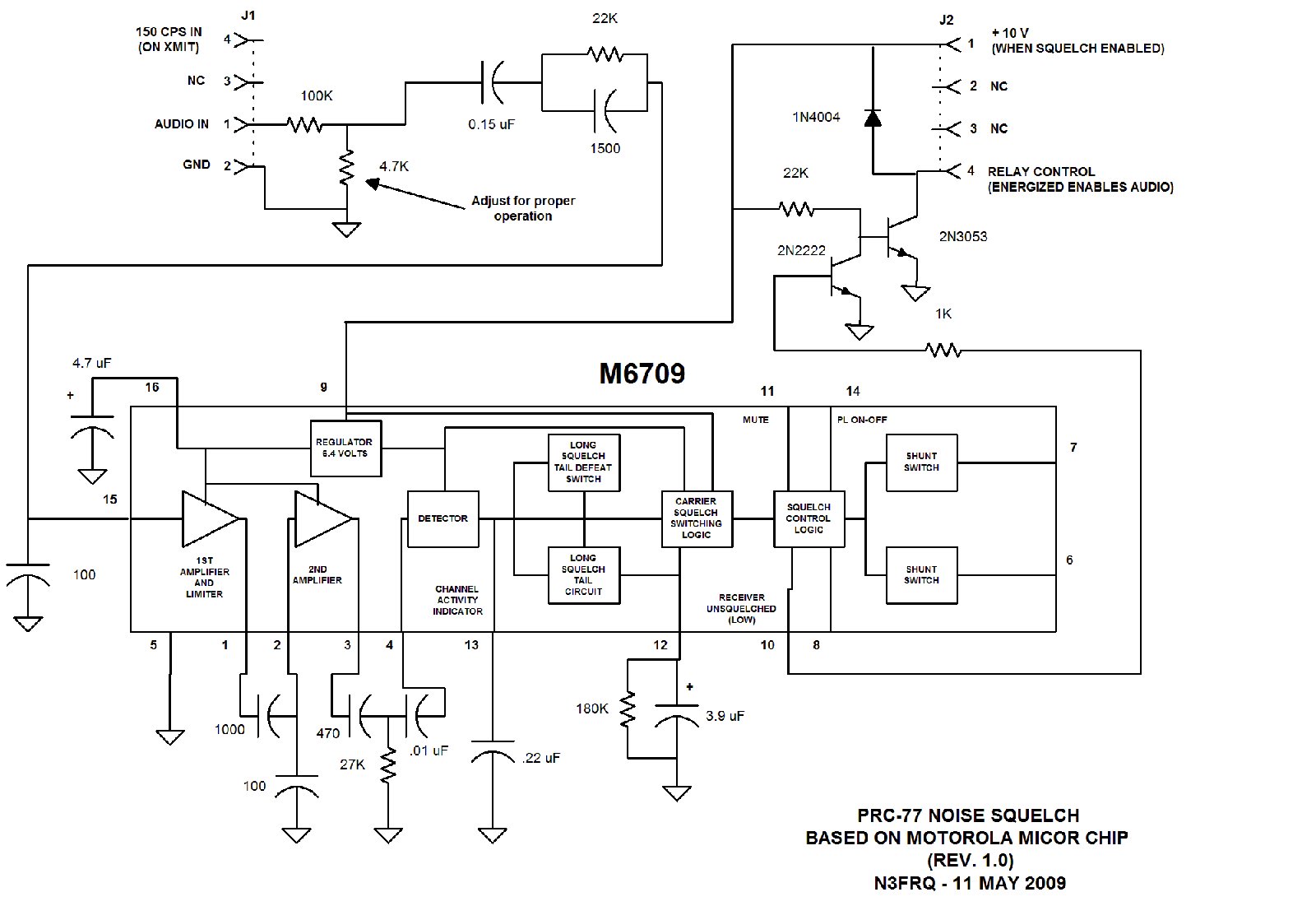
CLICK to enlarge N3FRQ
The N3FRQ circuit gives details of the M6709 squelch IC that is used by W3KCC on his board which was described at the beginning of this page.

CLICK
to enlarge
Canadian
noise squelch made for the PRC-25/77. I've never tested this module. One
or two of the military radio collectors claim to have this module but
have not shared any "test or eval" information.
Test Info submitted by Craug N3TPM. "I have one of those A24 canadian noise squelch modules in my PRC77. I was able to adjust the sensitivity level to match the tone squelch unit and the operation is transparent. I was able to pickup Ft Hood range control on 30.45mhz with the tape whip antenna equally well with either squelch setup. I would say that reception range is about the same with either unit. I have been using it for about 20 years now. I have never taken any voltage measurements but my RF signal generator gives me about .5uv for the squelch to open and 20db quieting at about .6uv.

Schematic
drawing by KA3AIS CLICK to enlarge
Squelch
circuit 73 Magazine, Jan 1980. Remarks by Bill KA3AIS. "The 73 magazine
article with the squelch is indeed in the January, 1980 issue. If you
look, there is a CB to 10M. FM conversion article which starts before
page 124, and another article which starts on page 131. The squelch circuit
I drew is abstracted from the FM 455 Khz. IF portion of the conversion/perversion.
The Input to the Squelch is buffered/amplified audio - just after the
FM detector in the IC the author uses. The Output of the circuit is switched,
so it can be used to control an audio amplifier IC, relay, etc. I drew
the SQ. circuit probably as an exercise (I may have been away from the
free photocopier, too...) It embodies the basic principles of a cheap,
easy to build, and hopefully reliable circuit for the time period. The
fact that it is installed AFTER audio is detected means it can be adapted
to most FM receivers. I seem to recall giving some thought to squelch
operation(s) and boiling it down in my mind to the best compromise type
circuit. I probably had/have other notes, but nothing in front of me,
and likely nothing of real value which can be soldered together... The
article was written in 1980. By 1985, the Motorola receiver-on-a-chip
ICs were finally common and cheap. P/N's like MC3357, MC3359, MC3362,
MC3363, etc. Motorola integrated this type of squelch circuit into the
ICs."
My notes: I like the single IC circuit with the output
to a switching transistor for the PRC-77 Squelch Relay. The IC MC3403
can be configured as a single supply Op Amp and can be powered with a
voltage between 3 and 30 volts which makes it perfect for the PRC-77 application.
RETURN K4CHE Index