Additional HBR BFO Circuits
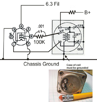
Here
is a schematic of Ian Wilson's BFO using the Command Set series coil in
a
test circuit.
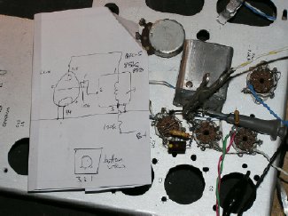
Ian
Wilson
"This
worked over supply voltages from 90 to 250 volts. The tuning range is
about
83 to 86.2 kHz. You might want to follow Breck's modification to disconnect
the internal variable
capacitor to get a bit more range." "Note the the connection
to the can is necessary. For my lash-up
I have a solder tag under one of the screws holding the base to the can."
The
BFO circuit shown below is for the HBR-16 using a 6BH6 and was
constructed by Pete WB2JWU
photo
WB2JWU
Pete was unable to obtain a center
tapped coil and changed the 6BH6 circuit to a Colpitts.
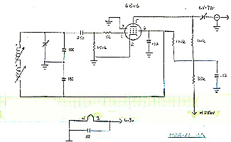
Here
is the original HBR-16 6BH6 circuit. Note the tapped coil.
Notice that the HBR-16 uses a variable capacitor C9(1.7-7 pF trimmer to
control injection.
On the HBR 14 W6TC used a "gimmick" capacitor. On the HBR-14
that I built I later changed the gimmick
to a small piston cap which can be seen on the previous pages.
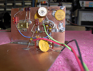
Photo
WB2JWU
Note
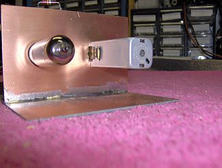
the use of copper clad PC board material for Pete's bread board. The board
is
easy
to solder and makes it easy to establish ground connections and to mount
components.
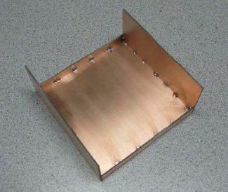
Photo
from QRP Builder WA4MNT
The
builder might consider using copper clad PC board material for his BFO
enclosure.
"QRP
Builder" has a nice article on constructing a chassis using PC material.
http://qrpbuilder.com/
