HBR-14 Receiver BFO
The first HBR receiver circuit the builder should construct is the BFO assembly. On this page you will find construction techniques and recommendations for the BFO. Finding the original BFO coil can be a daunting task and alternate circuit suggestions are offered here. In addition there is information on using the BC-453 BFO coil. There is a lot of information on this page and most of it is directed at the Novice builder.
Why construct the BFO first?
Several Reasons:
1. The coil and its circuit enclosure will determine location
of other parts on your chassis.
2. The actual "Tapped Hartley"coil assembly may
be hard to locate and a alternate plan needs to be made.
3. The coil frequency is linked to the IF frequency, if you
acquire the IF coils first then that determines the BFO coil frequency
etc. The builder needs to decide which frequency.
4. The BFO circuit is fairly simple and will get the builder
back in the building mode and most important the testing mode. The receiver
in my opinion should be built built "backwards"one stage at
a time starting with the last audio stage and then that stage tested before
proceeding. This way you will wind up with a receiver that works and not
a chassis full of problems.
5. Lots of builders build the receiver and then get hung up
on the BFO circuit,best to knock this one out at the beginning.

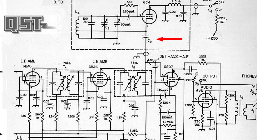
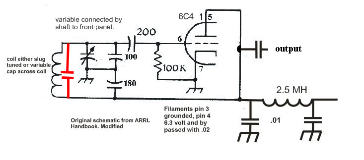
This is the original BFO circuit used in
W6TC's HBR-14. Note that the BFO coil "L4"is tapped and a Hartley
Oscillator circuit is used. Finding a "tapped coil" or the original
Millen coil will be difficult. So I recommend changing the circuit to
a Colpitts and eliminate the need for a "tapped" coil.
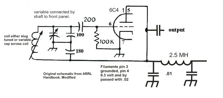
A suggested Colpitts substitution circuit for the BFO.
Note that the main coil is not tapped and will be much easier to find
and or modify. Don't panic I am not suggesting
that we modify the entire receiver but you will discover that finding
a tapped coil with the tap in the proper position for feed back is going
to very difficult. You can spend years trying to
find a suitable tapped coil or just do a Colpitts circuit and get on with
building a receiver. The mission is to build a HBR receiver that
hundreds of amateurs all over the world have done.
Read This: Don't skimp on the 2.5 Mh choke, you do not want the BFO signal
on the B plus line. Use shielded wire for the B plus and filament connections.
Use shielded wire for the output wiring.
W6TC build the HBR series with a enclosed "shielded"BFO
and it was mounted on top of the chassis with a shaft extension to the
front panel.
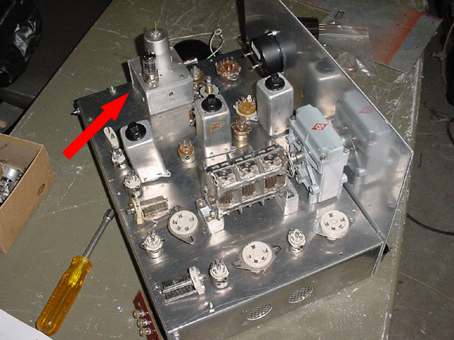
Decide what type and size of
the small BFO box enclosure as it will effect parts placement on the chassis.
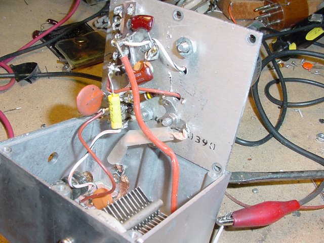
In this photo all the components are mounted on the main 10X15 in chassis.
The main chassis is smaller than usual as I used an external power supply,
a technique that I recommend to the novice builder. Using an external
power supply prevents a lot of hum problems, over heating etc.
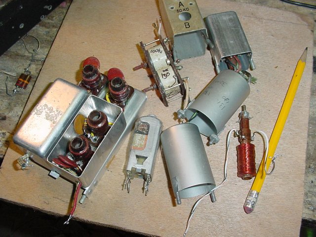
Selecting a coil type depends on your sources and the circuit that you use. All of these came from a 1 hour visit to a hamfest flea market and are candidates for a basic Colpitts circuit.
I recommend that you choose a BFO enclosure with a lid
or use a small chassis and turn it upside down and fabricate a bottom
plate which becomes a lid. Easy access will help you later in alignment
and possible trouble shooting.
I used a small circuit board cut into squares and mounted
on the floor of the small BFO enclosure to mount components. With the
circuit board to mount various components I cheated a little to conserve
space inside the enclosure. Lots of HBR's have been build with an enormous
box mounted on top of the chassis for the BFO which takes up a lot of
chassis space.
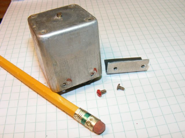
My 3 inch by 2-5/8 in enclosure conserved served valuable chassis space
on my 10X15 inch chassis.
No matter which BFO circuit you use I recommend
bread boarding the circuit.
At the low frequency the circuit operates component placement and lead
lengths are are not critical. The "bread board" above was fabricated
from a piece of copper clad circuit board. The 6C4 tube
socket was mounted up side down. Use of the copper clad board
allows easy soldering of the "ground side" of leads, components
etc.
The builder may choose to use the BC-453 BFO "CW
Oscillator"coil Z4 as well as the BC-453 IF coils. The BC-453 coil
is not my favorite choice for the BFO circuit but can be made to work.
The BFO coil in the original configuration of the receiver utilizes two
windings a primary and a secondary. Its operating frequency was 85 Kcs.
However I was unable to develop a reliable circuit using the coil in its
original configuration with a 6C4. Modifications of the coil were made
and will be shown on this page.
New Info below with a link posted Dec20, 2011
But later I received a circuit from Ian Wilson
where he used the Z4 coil in its original configuration so I must have
made a mistake when testiing the circuit. In addition Pete, WB2JWU send
me his modified HBR-16 BFO circuit
NOTE: Look
at these pages before proceeding:

Unmodified
BC-453 BFO "CW Oscillator"
MMF = pF
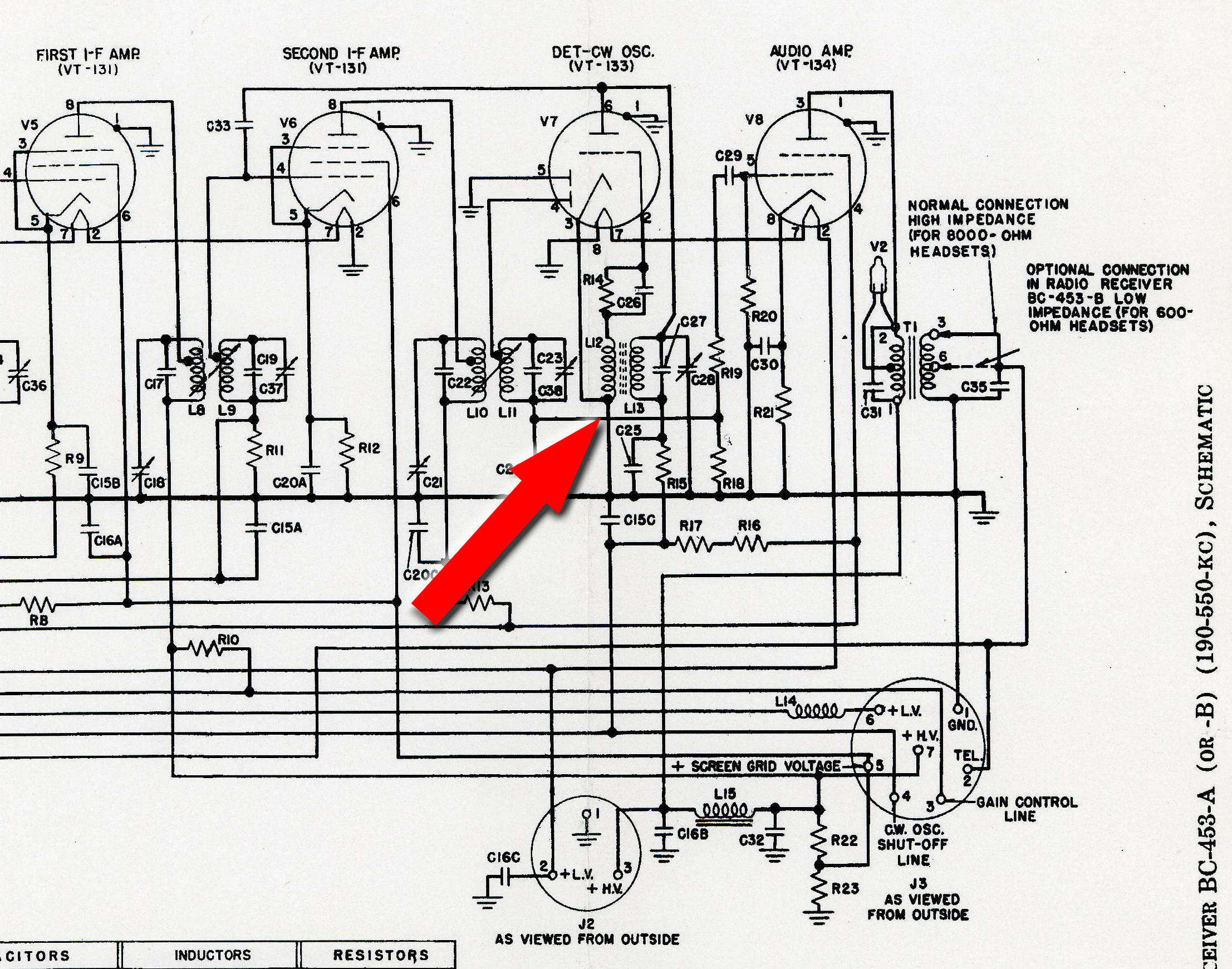
BC-453
Schematic
Basically to use the BC-453 Z4 coil you have to disconnect the primary L12 and then use the secondary L13 in a Colpitts circuit. In addition some capacitors are cut and some basic rewiring is in order.
Some advantages of using the BC-453 coil are:
1. Very robust construction and good shielding of the coil
2. A very mechanically stable coil. No slugs to move or wear out.
3. Easy to modify.
Some disavanges are:
1. Mounting requires external brackets to be fabricated.
2. Tuning by the internal capacitors only covers a couple of Kcs.
3.A padder capacitor will have to be added to get the coil on the correct frequency.
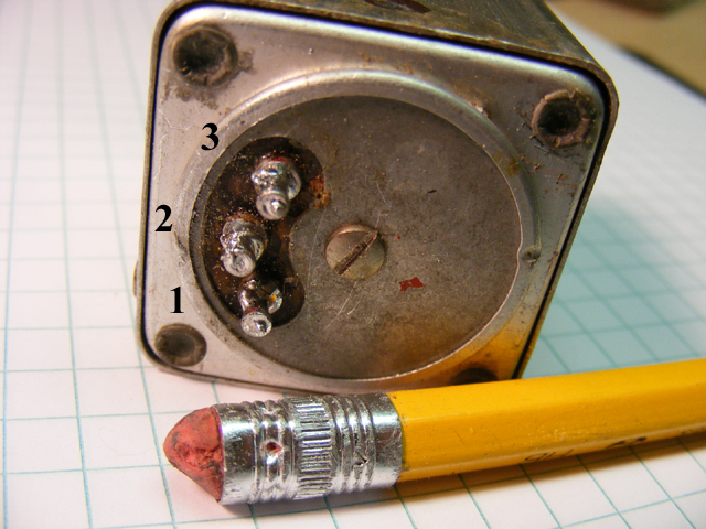
Shown is the pin out of Z4.
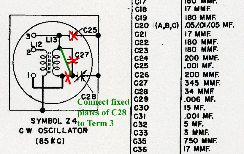
Suggested modifications to CW Oscillator Coil Z4.
1. Remove and discard C-25 (.001) brown postage stamp capacitor.
2. As you are removing the ground lug of C25 you will notice one of the
leads of L12 is also connected to that same lug going to chassis ground.
Cut both leads of the L12 to isolate L12 completely from the circuit.
L12 is the smaller of the two coils and is located on the bottom of the
coil assembly.
3. Disconnect C27 a 345 pf button mica (metal encased cap) which goes
across L13. Later on you will replace this cap with an approximate padder
of 150 pf later in the actual Colpitts circuit this will be external to
this coil assembly.
4. Note that in the original wiring the variable cap C28 is connected
from L13 to chassis ground. This capacitor will vary the circuit a couple
of hundred cycles. Isolate the fixed plate connections and connect to
terminal 3 of the assembly, thus placing C28 at the other end of the coil.
Due to the mechanical layout the rotor of C28 must remain connected to
chassis ground. By moving the fixed plate connection to the top of L13
will provide the builder with more "swing". This will give several
Kcs of coverage and will allow the builder to make adjustments of the
coil through the screwdriver slot on top.
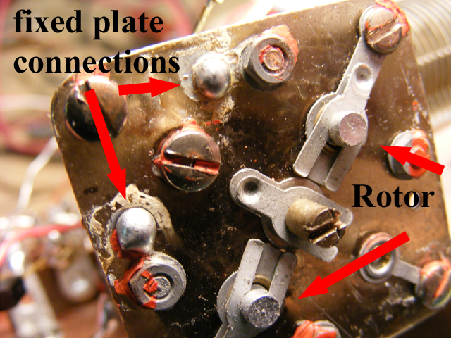
Z4 assembly top section.
The "fixed" plate plate wiring connections are on the other side of the solder joints shown.
Approximately 150 pf will be required to pad the Z4 coil and bring the modified coil down to 85 Kcs. Padder shown in RED. BTW W6TC had to use a 150 pf across the coil(132 Kc Millen 612-M5) that he used for the BFO in order to bring it down in frequency.
Checking for initial operation of the circuit.
1. You can use a scope and a scope probe and hold it near(within an inch
or so)of the circuit to check for operation, but touching the coil with
the probe will stop oscillation.
2. The circuit should draw around 10-15 mills of current.
3. You can use a "snoop loop" connected to your frequency counter.
4. You can listen on a receiver. Hint: the 6th harmonic of the BFO frequency of 85 Kcs would be 510 Kcs. The sixth harmonic of 100 Kcs would be 600 Kcs, etc. Take piece of wire and use it for an antenna for the receiver an lay it near the circuit.
5. After you get everything working and finished be sure an check for
vibration
problems.
Short Video
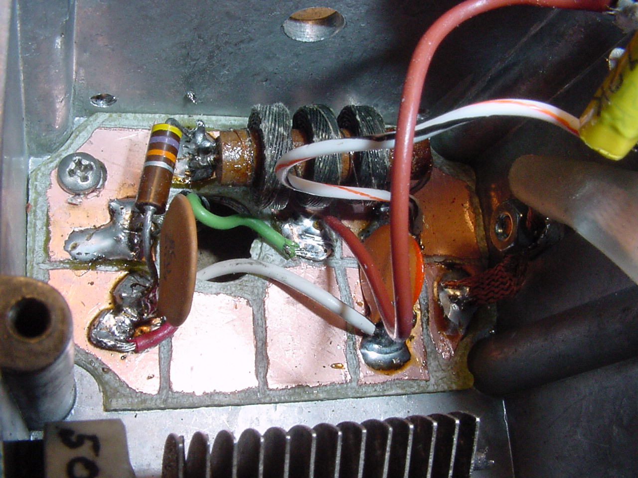
Checking for frequency:
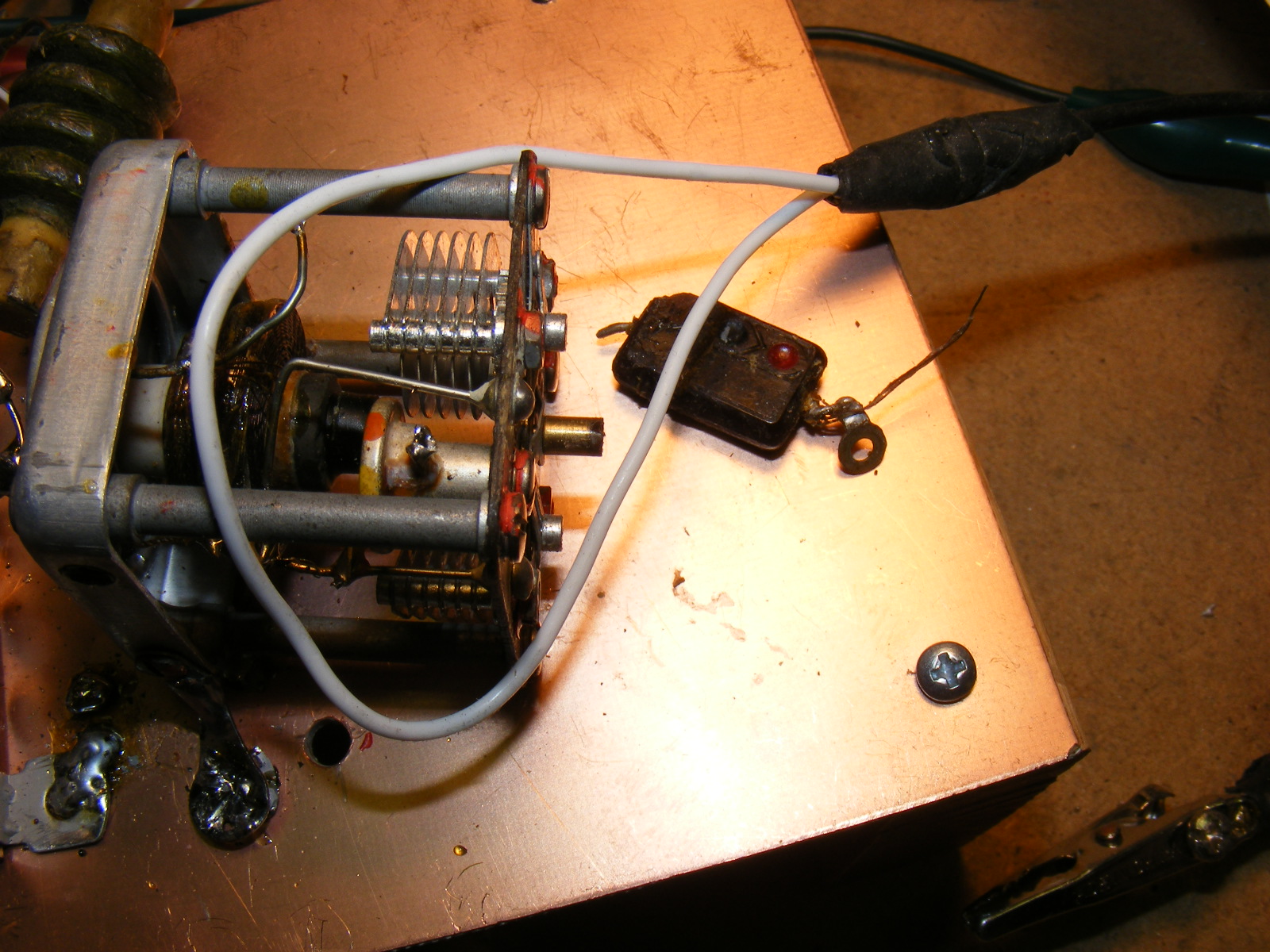
1. You can use a frequency counter and "snoop
loop" on the end of a length of miniature coax to couple to the coil
while you are testing the Colpitts circuit. (The assembly cover must be
off) This snoop loop will effect the frequency slightly of the circuit
under test but for initial testing and to get the coil close to the IF
target frequency this procedure works fine. The brown cap laying next
to the coil is C25 which was removed.
Note: Initial testing of the BFO coil
with the shield off speeds up the process because it is easy to sample
energy from the coil but when you put the shield cover back on the frequency
of the coil goes higher, usally 10-20 Kcs. - - - so adjust accordingly.
2. You can position your scope probe near the
coil and the use your signal generator to produced a
lissajous pattern.
3. Or just use the 6th harmonic and listen on a receiver using a piece of wire next to your circuit as the receiver's antenna. 6X85=510 Kcs
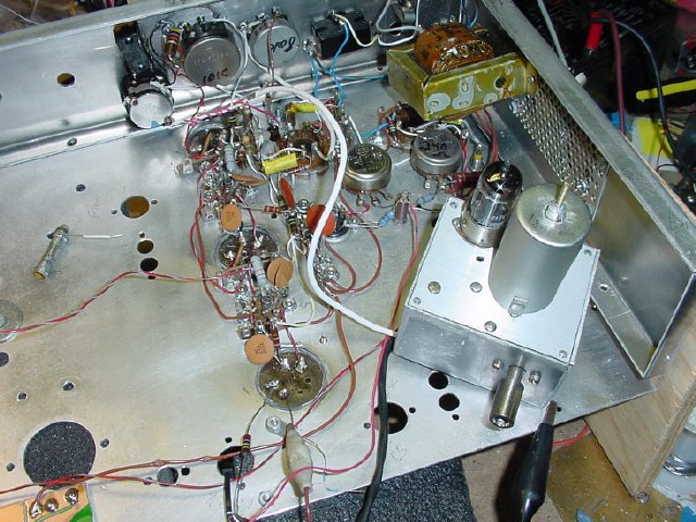
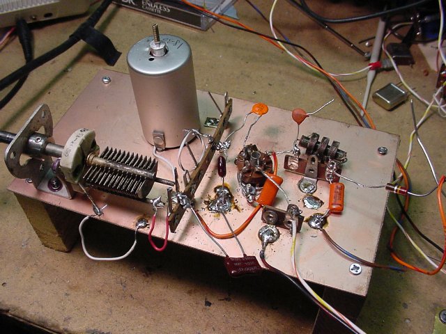
When you are ready to check your BFO with the actual receiver circuits accomplish your initial testing with the BFO laying in place on the chassis. In this photo the Audio, Detector and IF stages have been completed and I am injecting a IF signal and adjusting the BFO for a beat note or a tone created by the mixing of the BFO with the IF signal.
Note: The receiver in the photo is being built "backwards" starting with the audio stage.
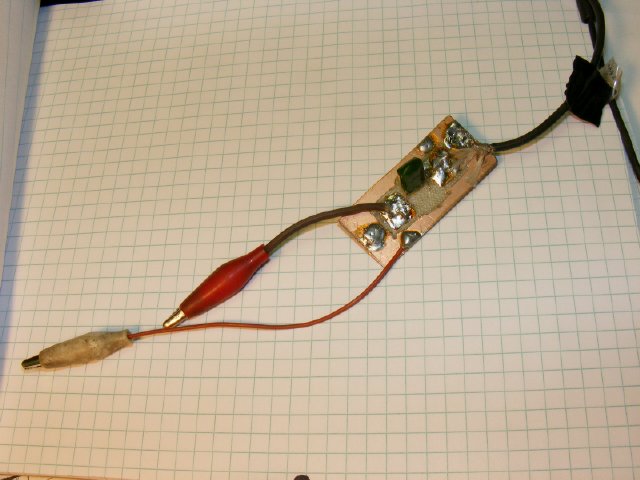
When injecting a signal from a signal generator make up a test pad with
clip leads, on the pad is a isolation capacitor a .01, this little gadget will come in
handy many times during construction of an HBR.

After the receiver was finished and during alignment
I decided to do away with the BFO injection "gimmick" capacitor
(two wires twisted together)and used a small piston trimmer, not really
necessary but I had the part on hand it its installation allowed very
small adjustments of the BFO injection.
This capacitor is labeled
C9 in the original HBR circuit and is shown here: