

These
pages contain construction details for a BC-611 DF antenna coupler as
well as tips on checking the AN-190 DF antenna.
PLEASE
NOTE: I've posted a short video on using the BC-611 without using a AN-190
antenna on a hunt. This video "Close in DF Techniques" is posted
at the end.
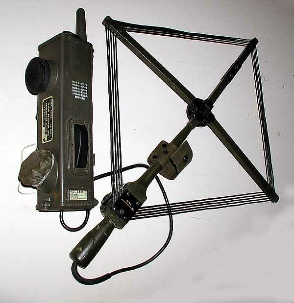
Problem: Most of us do not have a BC-1387 antenna coupling unit.
We have the AN-190 antenna but no way to connect the antenna to the radio.
Actually I had never seen an actual coupling unit until our Gilbert meet where Dave Kormanicki - KB3ELD bought one in for display and even displayed the complete MC-619 "Homing Modification Kit".

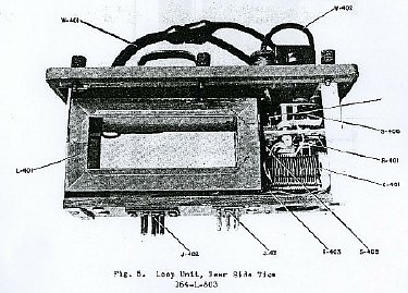
The BC-1387 coupling
unit converts the AN-190 DF antenna balanced output
to the BC-611 antenna circuit. A small clip is placed on the BC-611
retracted antenna when the coupler is in operation.
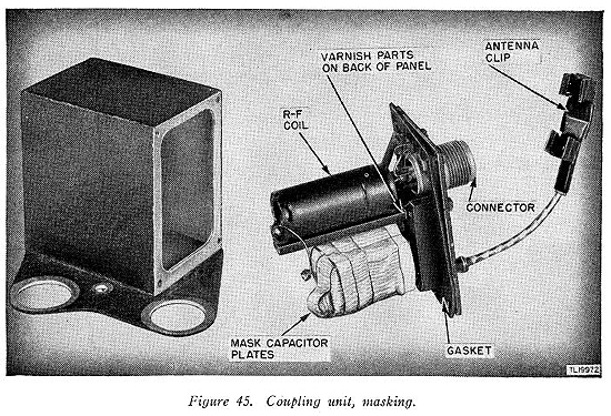
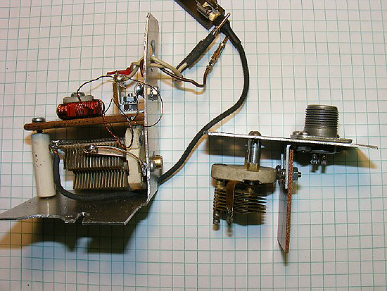
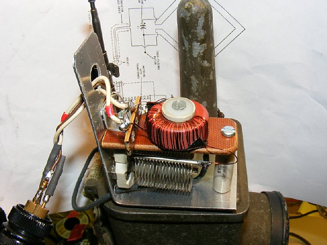
There are only two major components inside the box. An RF coil
transformer and a variable capicator.
CLICK
TO ENLARGE
The DF antenna is basically
a closed loop and feeds the coupling unit which contains a balance autotransformer
coil and variable capicator. The variable capicator tunes the 4 turn primary
winding of the loop to resonance. The secondary winding (pickup loop)
feeds the autotransformer/variable capicator circuit which matches the
BC-611 antenna circuit.
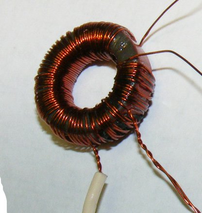
Duplicating
the BC-1387 coupling circuit is not possible without a coil. A coil can
easily be fabricated using a "Red" T80-2 RF Toroid. The
diameter is .8 (point 8) inches. Wire was # 28.
My favorite
distributor for toroids is: Kits and Parts.Com. Their web
site contains very useful information as well a calulator for winding
coils.
http://www.kitsandparts.com/toroids.php
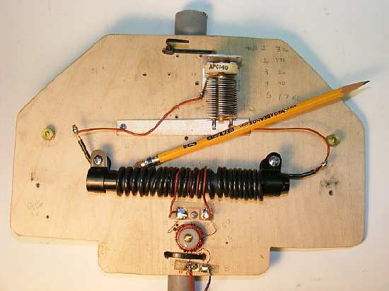
With a coil and a variable cap you have a coupler.
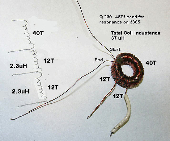
Scale:
4 squares equals 1 inch.
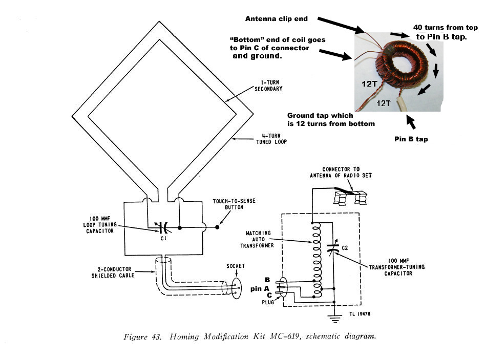
Autotransformer confirguation.
The
coil looks big but remember the diameter is just slightly larger than
3/4 of an inch.
I used a piece of phenolic to to make a shelf to mount the coil - at first I used a ceramic standoff but later just used a simple bracket.
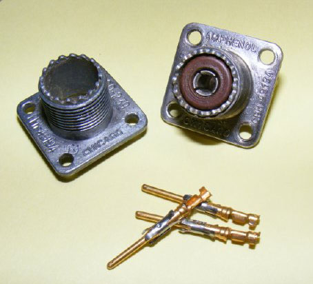
An emergency connector can be fabricated.
Grease
the AN-190 connector to prevent the epoxy from
sticking - insert the pins and then fill with epoxy.
Or skip
the connector and just put pins on the leads and plug them in. Scrounge
the pins from a old connector that you don't need but one that you will
probably need later after you have removed the pins. Never fails.
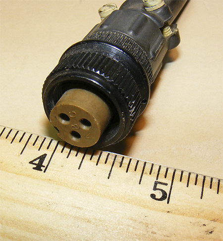
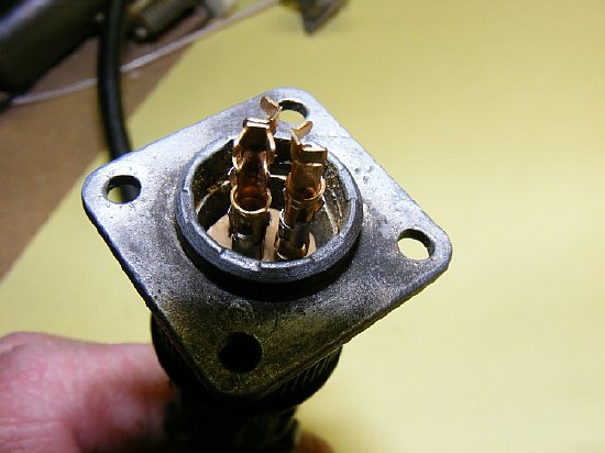
Don't
get pins A B and C on the antenna feed line connectors
mixed up. A and B should show continuity with
an ohm meter.
C is coupler case ground and shield ground.
Most of my testing was done by just using the pins on the wires and inserting them into the connector.
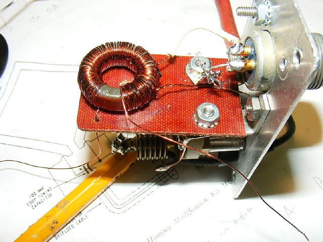
The phonolic board can be drilled and the wire fed through.
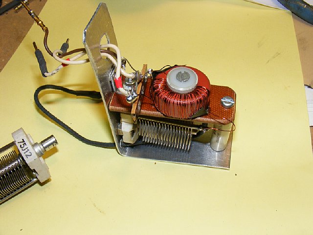
Small sheet metal brackets hold the board. A solder lug provides a
convienent ground point.

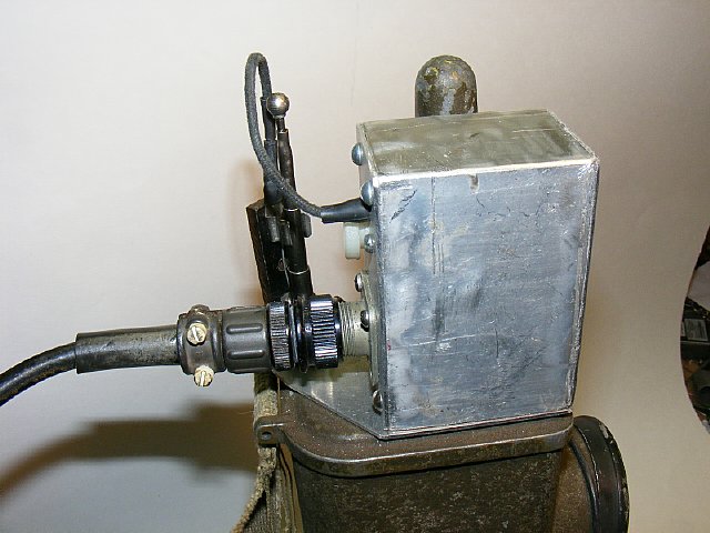
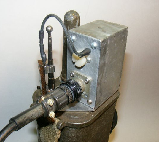
Side view of a completed coupler. A plastic washer holds the coil.
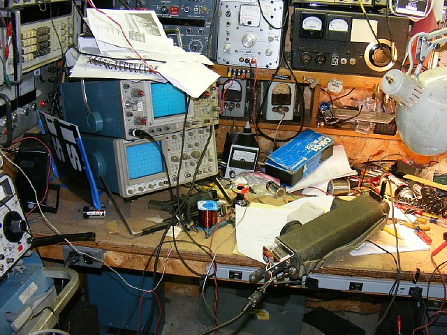
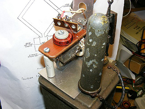
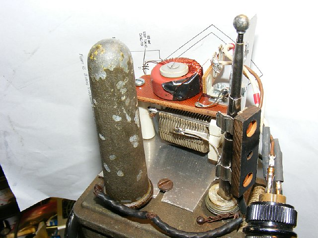
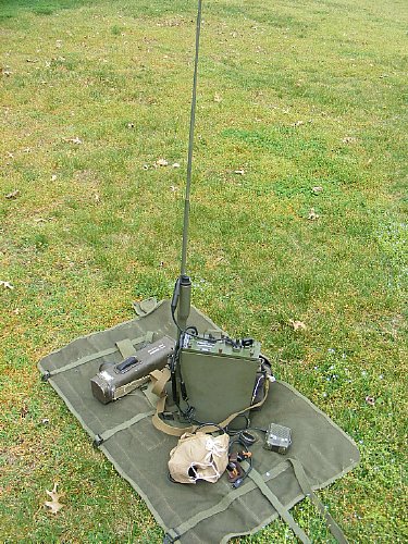
My
bench setup for testing.
VIDEOS:
Bench
Test AM-190 and Coupler
Bench
Test 2
Bench
Test 3 Null Demo
Plenty
of info on DFing in TM-11-235.
A good source of Military manuals
is WA5CAB. Robert provides
really excellent TM reprints complete with updates. The best part is
they do not smell musty. Ask my wife.
http://www.vendio.com/stores/wa5cab/
Note the use of a fuse holder as a clip for the antenna.
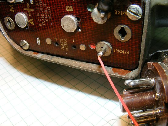
A
quick and dirty way to provide a temporary external earphone
lead for the BC-611. Dress the lead under the lid and close it carefully.
NOTE: Pins from a bad octal tube can be used. BTW the tube pins can also
be used to convert HC-6 crystals to fit FT-243 sockets.
http://k4che.com HC-6 Crystal Conversion
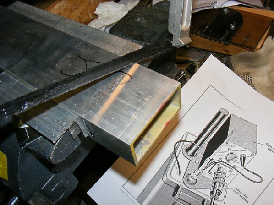
I fabricated an enclosure. My general rule is that if you can not
build a project with just hand tools then don't start the project.
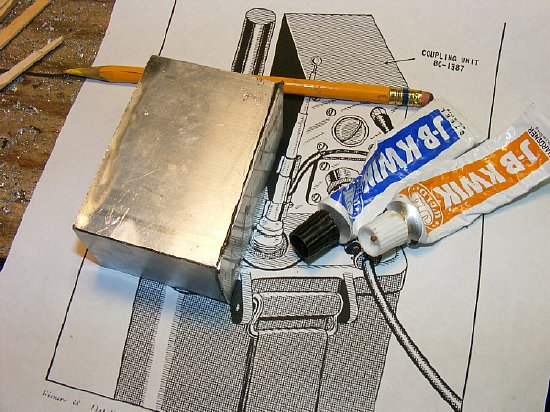
One of my favorite tools is J-B Weld.
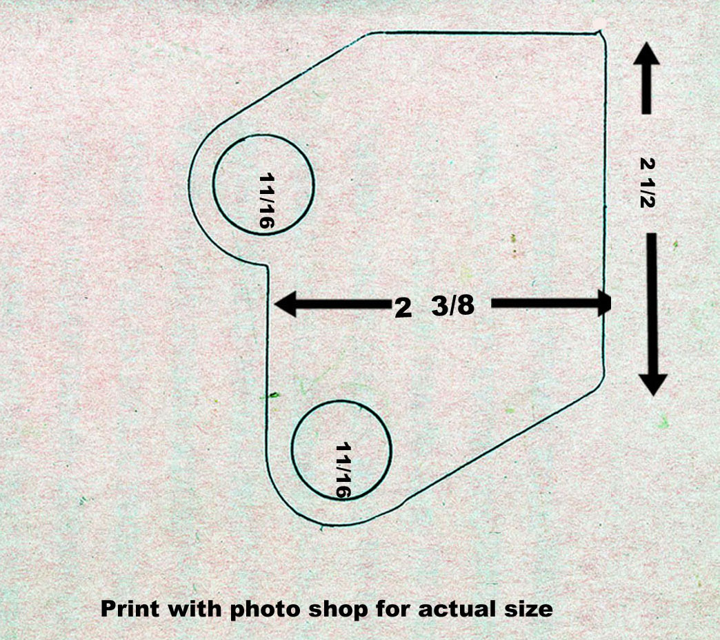
Bottom
Plate measurements taken from Dave's unit.
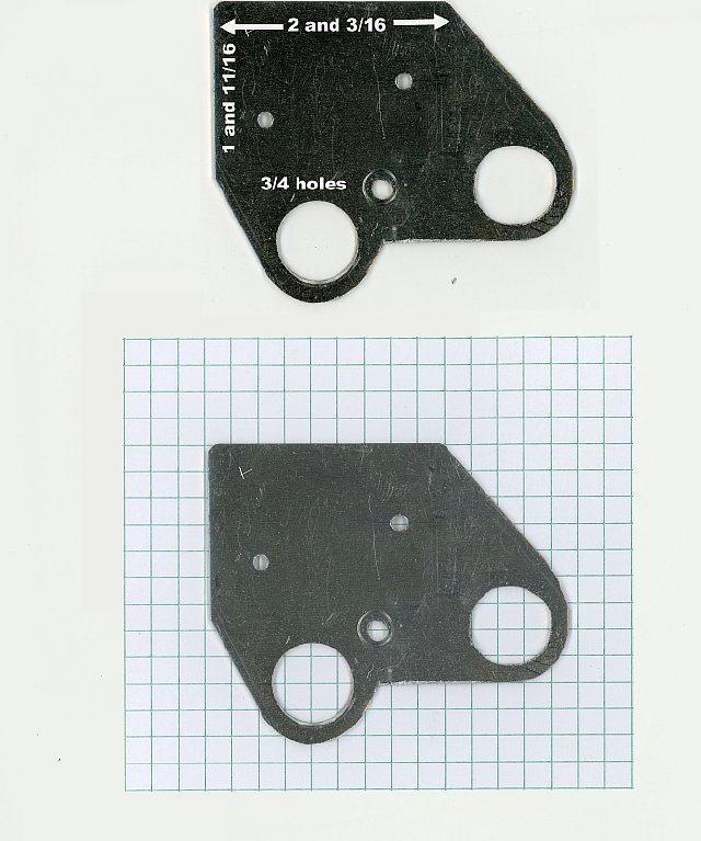
Graph
paper photo of my fabricated plate that I made without
having the actual unit. It was just slightly too small but close enough
for
"Government Work". Four (squares) equal one inch.
I used black wrinkle spray paint then over painted with a dull green.
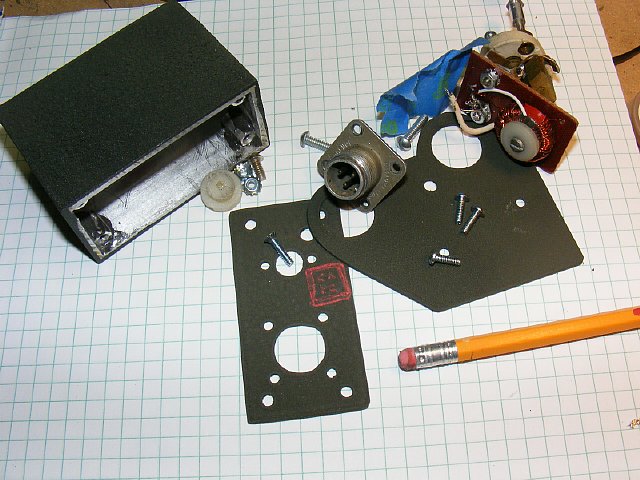
Final testing and ready for paint.
Note:
On my fabricated unit I placed the access hole
for the tuning capacitor
in the middle, on the actual unit it should be
offset slightly to the
left.
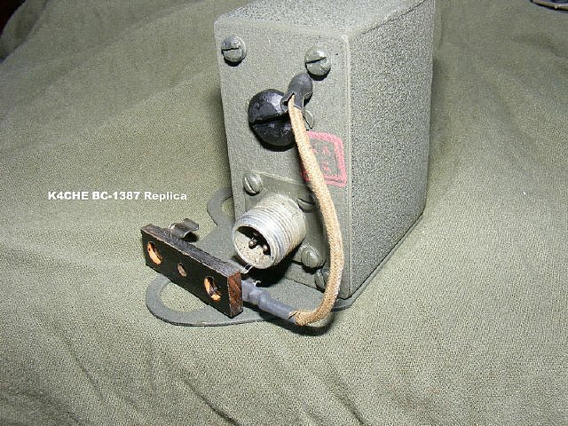
Fini, for fun I used a piece of rubber and carved out an "Inspection Stamp".

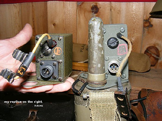
A size comparison. Dave's unit is on the left and my fabricated unit is on the right. So I was a little off with the my fabricated housing which was just a little larger than the original.
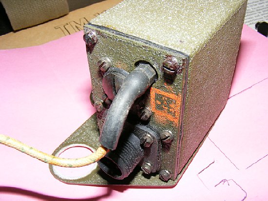
Photo of an actual unit owned by Dave. Note that the capacitor access is offset slightly to the left.
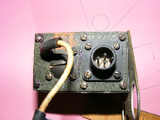
Dave's Unit.
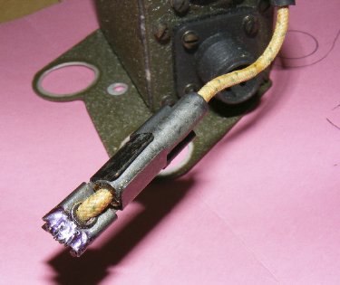
Photo of the actual antenna clip.
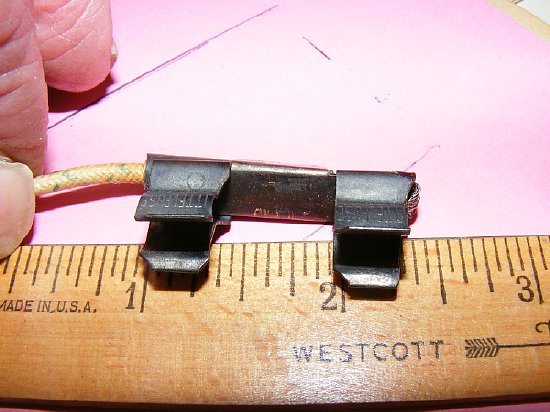
Actual antenna clip.
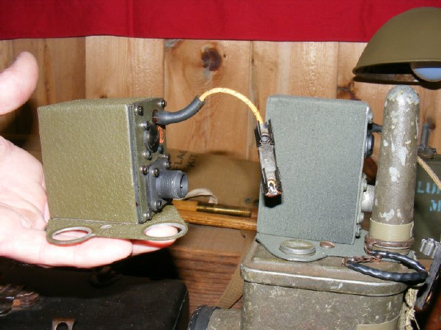
Comparison of Dave's unit and my fabrication.

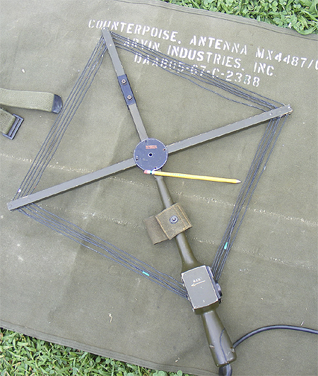
Its a traditional loop antenna slightly larger than the radio. Larger is better
as that will provide more capture area.
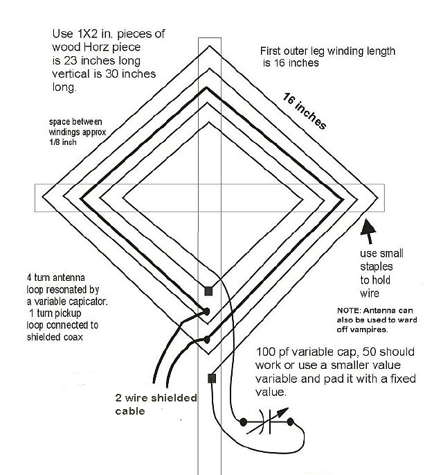
A
couple of pieces of wood, some wire and a variable cap and you have a
copy of the AN-190 antenna circuit. It is best to use a 2 wire
shielded cable to feed the BC-611 coupler. Radio shack has the
wire.
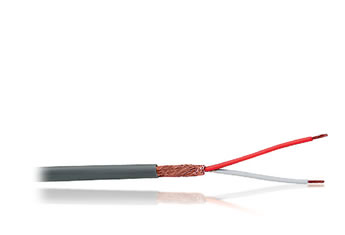
Radio
Shack 278-513
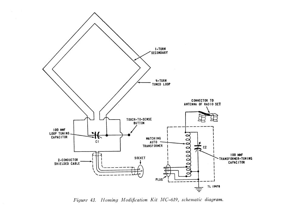
You have 4 turns resonated by the variable capacitor. You have one turn (pickup) that feeds the coupling unit via the 2 wire shielded cable.
The AN-190 is tuned to resonance by the variable capacitor. Tune for maximum noise.
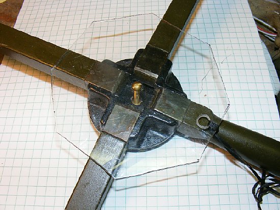
The wooden arms on the loop kept flopping around and would not stay in place as my wires were loose. I fixed that with a small piece of lexan and a bolt. Later I corrected the loose wires and the arms snap into place.
A photo of the actual insulation material that keeps the turns in place. All of Dave's equipment is in very good condition.
All my insulation was rotten and missing, I used small pieces of rubber to hold the turns in place. The previous owner tried silicon caulking and that did not work and made a mess.
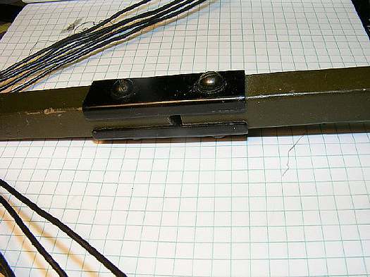
The top loop arm consists of two parts with a metal coupling that can be removed. You can remove the coupling to adjust the top arm.
Adjustment slot

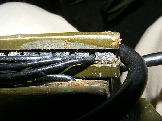
The phonelic cover was designed to "clamp" the wires and can be removed for access to the wiring. wires. If you have accessive slack in the wiring the remove the cover and adjust the wires and then put the cover back on to "clamp" in place.
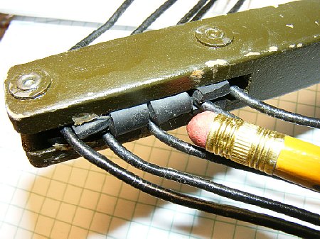
I removed the "MAX" cover and found this mess. The bolt sticking out is the "sense" connection. I cleaned up the area, installed new rubber underneath the wires and tighten the wires in place with the cover. Silicone caulking was not needed. Note the overlapping wires, this is not a mistake but is necessary to continue the windings and to transition from winding 1 to winding 2 etc.
Practical
loop wiring diagram AN-190. Note the wires that cross each other
inside the handle.
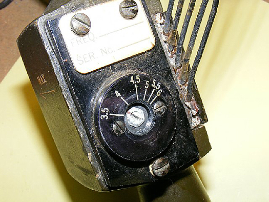
Be
sure and inspect the variable for corrosion between the plates.
Note: In this photo there is a 5 pf fixed capacitor across the variable that is used to help calibrate the dial readings on the front by adding additional capacitance to the variable. The 5 pF cap is not shown on the schematic.
.JPG)
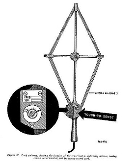
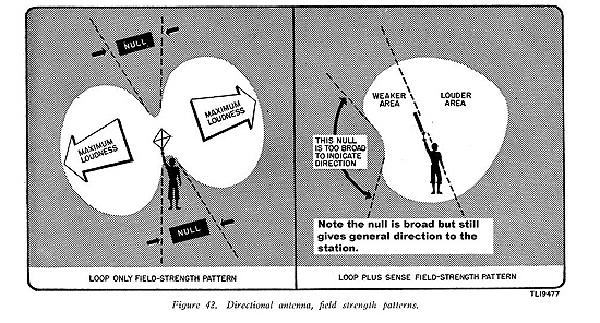
The loop wires are fed into the wooden housing under the front cover.The wire spacing is the same as on the legs. Once inside the box things get a little haywire but at this low frequency this can be allowed. The arrow indicates max signal direction when you touch the "sense button" with your thumb which up sets the pattern - you then turn the antenna to for maximum signal off of the ends of the antenna rotating it 180 degrees. This will help eliminate one of the two directions obtained previously by nulling. Confusing? If all else fails read the manual. NOTE that the MAX arrow is aligned with the legs of the antenna.
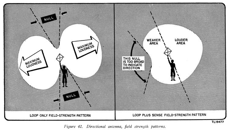
The figure 42
in the manual can be confusing describing "SENSE" operations.
Looking at the right diagram they show a "null" when using SENSE.
Note the orientation of the antenna. They are comparing the pattern
when using the sense button. The diagram above is technically correct.
But I have never been able to detect the broad null when using the sense
button so I've redrawn Figure 42 below to describe what I've experienced
during multiple tests of the antenna.
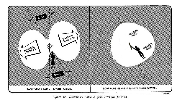
I've redrawn Figure 42
to illustrate the louder and weaker areas off of the "ends"
of the AN-190 loop. On the left is normal operations when two nulls are
present indicating that the transmitter is is located either North or
South of the operator. On the right is the pattern when using the SENSE
function. The operator has determined that the transmitter is to the "North"
and will proceed in that direction and take null bearings.
TIP: When
using the sense button it use is marginal close to the transmitter due
to the strong signal. Try wetting your thumb for better conduction to
the antenna to upset the pattern. Sometimes turn the max end away from
the signal and pulse the signal with your thumb will help determine which
side is max, if you are on the min side you should hear the pulsing
if your are on the max side you will not hear anything. Play with
it.
R.jpg)
Note the MAX arrow on the handle , it is is parallel with the windings.
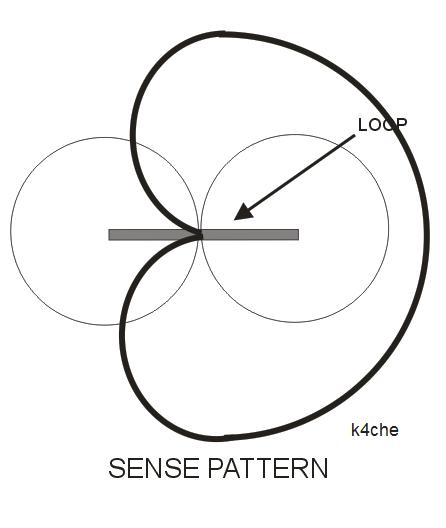
So to confuse you further. A perfect "Sense' pattern has been drawn over the loop pattern. Note that the "Sense" pattern has expanded off of one end of the loop due to more gain. This indicates the proper direction to the station and now you can proceed and use the null function of the loop. In practice with the AN-190 I have never experience this sharp of a pattern when using the Sense function. This pattern would be a ideal pattern where the "Sense" input is introduced 90 degrees out of phase by a precise tuning network. On the AN-190 it is a different story because you are using your thumb and touching a portion of the antenna which upsets the normal null pattern and a much broader pattern results. Simple but it works.
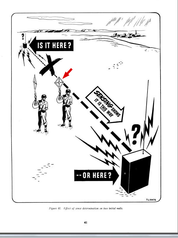
Figure
41 is somewhat confusing, the purpose is to inform the reader that SENSE
function will eliminate one of the nulls and help determine the correct
direction. The red arrow points to the original
soldier drawing where the soldier take two initial null bearings
but does not know which direction.The soldier on the left has the
antenna pointed correctly when using the SENSE button, the arms of the
antenna are line with the direction to the transmitter. He has rotated
the antenna back and forth 180 degrees and determined that the stronger
signal is in front of him. He will now proceed in that direction using
null bearings to find the transmitter.
Touching the
SENSE button with your thumb upsets the pattern. Only the thumb will work,
other fingers do not upset the pattern. Tip: Wet your thumb.
An interesting note, the DAV-2 loop is contained inside the wooden case.
The DAV-2 has the luxury of
have a very large vertical antenna that can be utilized to provide a "Sense"
input. But what is suprising is they do not use a complicated phasing
network, they inject the vertical antenna signal through a 100K resistor
into the loop circuit. Assuming that the 100K is used to reduce the large
amount of signal and to provide isolation. KISS
More
on the DAV-2 later.
A substitute for the AN-190 DF antenna - a ferrite loop antenna with matching/decoupling transformer. More details on:
http://k4che.com/DFloopstick/DFstickpg1.htm

Pull the transmit crystal
from your set and use it in this test oscillator and hide it in the back
yard for practice. Attach a 3 or 4 foot antenna to C4.
Details
of the above circuit can be found at:
http://www.geocities.ws/raiu_harrison/mwa/tech/circuits/osc-xtal.html
K4CHE "Close in DF Techniques using a Basic BC-611 without the AN-190 antenna.