
Ferrite
Rod DF Antenna Construction k4che
Mission: Construct a small DF antenna for "modern" radios or
to use as a substitute DF antenna for the BC-611. Keep
the design as simple as possible. Frequency
3.885 kcs.
NOTE:
On this page you will find information for building a substitute DF antenna
to be used on the BC-611. In addition details are provided for a small
compact loopstick DF antenna to be used on a modern solid state radio.
A lot of test results are shown here - - - I suggest that you read all
of the page before making a decision on building.
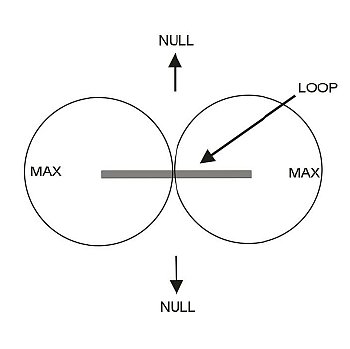 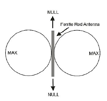 |
The Ferrite Rod antenna pattern is different
from a conventional open wire loop antenna as the null is off of the ends
of the antenna instead of the sides. When using either a loop or a ferrite
rod antenna the null can be used to determine a direction to a transmitter.
Ferrite rod was fairly scarce when the engineers designed the AN-190 but it can be used to make a smaller DF antenna.
The loopstick antenna is a lot smaller than the AN-190 and that is the good news. But the bad news is the loopstick will have less gain and less capture area but does provide a very good null to indicate direction.
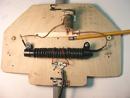
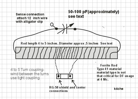
23 turns #14 wire and a 100 pF variable. The wooden board is oversized as it has been used on several VLF loopstick antenna experiments. How did I arrive at the 23 turn figure ? Simple - I wound wire on the rod until I ran out of room.
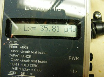
22-23
Turns usually provided an inductance close to 35-40 uH
A handy online resonance calculator can be found at:
http://www.deephaven.co.uk/lc.html
Once you have measured a coil inductance value Vs turns on your particular rod material you can compute different winding changes etc. An interesting page for calculations can be found at:
http://chemelec.com/Projects/Inductor/Inductor.htm
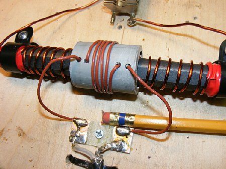
Numerous
coupling turns usually 2 to 6 turns were tried including this "variable"
unit. Positioning the coupling off center had very little effect on the
"null" and in this case antenna gain suffered due to the loose
coupling.
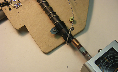
A Grid Dip meter is a quick way to check frequency of resonance. With the ferrite rod antenna you can get an excellent dip by coupling to the end of the rod. Make sure you have a capacitor across the coil to complete the resonant circuit when dipping and make sure the coax is connected to the radio. Coax length to the radio can effect resonate frequency - on one of my tests two additional feet of RG-58 lowered the frequency by couple hundred kcs. I used 4 feet of coax on all my tests.
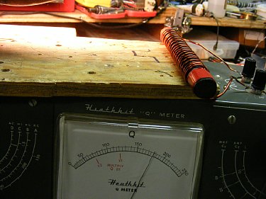
One of my favorite tools the Heathkit Q meter. My 22 turn loopstick had a Q of 180 at 3.8 Mcs.
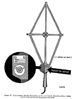
I started this ferrite rod
antenna project ( I call them loopsticks) by building a substitute antenna
for the military AN-190 that is used with the BC-611 and the BC-1387 antenna
coupling unit for directional finding duty. Details of the ferrite rod
loopstick DF antennas are on this page . However my loopstick antenna
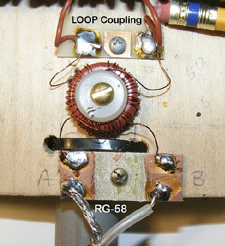
needed a coupling transformer to work well with the BC-1387 coupling unit.
RG-58 will work but a 2 wire shielded feed line is better.
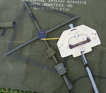
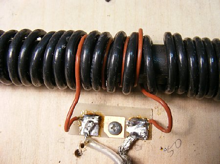
The transformer is wound on T80-2
toroid and consists of a primary of 5 turns and a secondary of 50 turns.
The 5 turn primary is attached to the coupling link that is wound around
the center of the rod. The 50 turn secondary is attached to a shielded
pair of wires feeding the BC-611 coupler connector via terminals A and
B. C is shield ground. If you do not have any shielded pair wire you can
use Radio Shack audio cable.
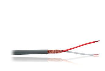
Shielded pair of wires used for lead in. Radio Shack part number 278-513
A working antenna
design for a "modern radio" I wound several different antennas
using various turn counts. 50 Turns is recommend for best gain.
Use a variable trimmer in the 5 to 50 range.
TURNS PROBLEM: You want maximum turns for best gain but you have to watch out for the self resonance of the completed rod if it get above your target frequency you will not be able to tune the antenna to resonance with a variable capacitor.
50 Turns max is recommended.

Field testing
was made easier by using this imported radio made by TECSUN. The set has
easy tuning, a built in attentuator and best of all has a easy to read
S meter scale shown above by the RED arrow.
Very very sensitive. Search for a good deal on Epay. The first one that
I ordered failed after 6 months but the 1 year warranty was honored. The
2nd one I ordered has survived a lot of local hunts and is still being
used. They make several versions but the PL-660 has all the features that
I needed.
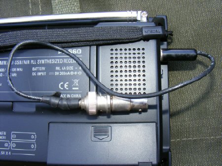
An antenna adapter will have to be fabricated. Standard 3.5MM plug to a BNC was used.
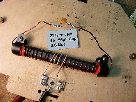
22 Turns No. 15 wire, the coupling loop was 3 turns. Antenna was off resonance but still provided a very good null but overall gain was down. So a quick "cookbook" rod DF antenna is to use a 1/2 inch rod- wind 22 turns and use a fixed capacitor of around 50 pF if you can't find some sort of variable capacitor in your junk box. Use a 3 or 4 turn coupling loop. This will produce a null. But additional testing with a 50 turns produced better results.
Half way through this project I experimented with different rods and lengths and I abandoned the large variable trimmer capacitor in favor of a small ceramic postage stamp padder cap. No real major improvement was noted with the longer rod.
An additional Capacitor can be added to the trimmer if needed.
The best over all "null" performance
was with "tight" coupling. 3-5 turns.
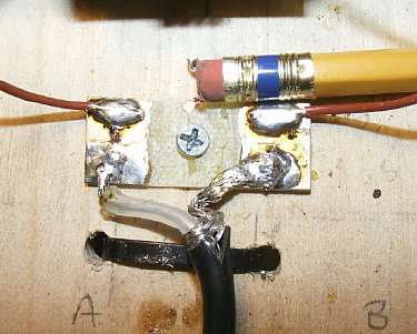
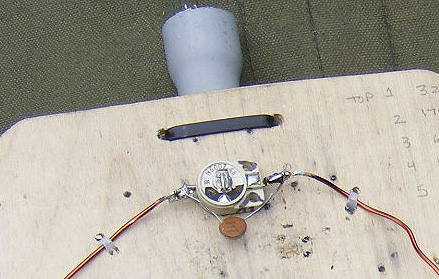
One of my favorite tricks when "bread boarding". I take a piece of PC board
and remove some of the copper to make separate copper lands for soldering - - - messy but easy to change connections when testing.
A shielded loop was constructed but no improvement was noted in null performance . My local electrical interference noise on 75 meters was not present during testing so I will reserve the shielded loop for later testing.
Note: I did not ground the shield so will have to do more testing with and without ground.
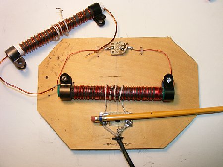
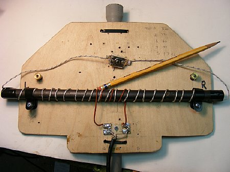
The use of the thin plywood backboard
mount allowed quick change of coils for testing. Note: the use of a small
ceramic trimmer capacitor. Value 7-45. Much better in the field than the
postage stamp trimmer as it easier to find the correct setting.
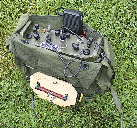
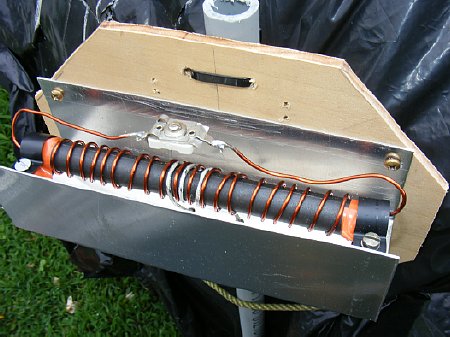
My field set up using a military radio. Note the loop stick is held by hand without a handle, this reduced the overall size and still produced an good null.
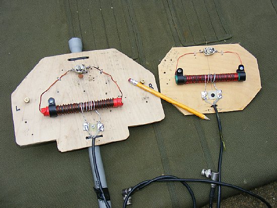
Comparison of a 30 turn loop left Vs a 50 turn loop right. The 50 turn antenna had more gain. The nulls were about the same.
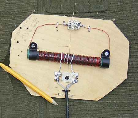
My best antenna, 50 turns of number 20 wire, capacitor was a trimmer value of 7-45. Inductance value was 180 uH. The 4 foot RG-58 coax lowered the resonance by about 500 kcs.
OPS NOTES:
When tuning the antenna to resonance listen to the no signal noise in the receiver you should hear a definite peak in background noise and you should be able to tune back and forth across this peak with your trimmer capacitor.
When testing the antenna for a null tune engage the receiver attenuator or tune the receiver frequency slightly off several kcs to attenuate the test signal or provide some sort of attenuation on the input.
When feeding the antenna with RG-58 expect one of the nulls to be slightly different from the other due to the imbalance. If that bothers you try using a dozen ferrite beads on the RG-58 to provide a current balun and mount the beads just below the antenna connection.
Problem, when trying to build a loop antenna at 3.8 Mc you can not get enough turns on the rod for decent gain so it is a compromise etc. You never see ADF antennas on airplanes for 3.8 mcs, but I assume the Lancaster Bomber is an exception.
Some approximate inductance values found for a 5 and
1/2 rod:
22 turns no. 15 was 35 uH
30 turns no. 15 was 54 uH
50 turns no. 20 was 180 uH
Use a short piece of wire with an alligator clip for sensing and attach it to one side of the capacitor. Play with it. But in my testing do not expect spectacular results. In most cases the loop fed with RG-58 exhibited more gain on one side of the antenna than the other and sensing was not needed and that provided enough sensing to determine the correct direction and to eliminate the 180 degree null problem. Sensing could be detected on receivers that could be tuned off frequency or had attenuation circuits. A "S" meter allowed good use of the sensing antenna.
Problem: Build a small oscillator and pull your 3885 crystal out of your BC-611 and use in the oscillator. Circuit shown below. Practice with your loopstick in the back yard. When your wife asks what are you doing. You answer "I am trying to take bearing on the that small transmitter in the back yard". She will immediately respond. "Well I saw you put it out by the tree, don't you remember where you put it ?" You then try and explain, - - -this dialog will last quite a while.

Attach a short antenna to C4.
Details of the above circuit can be
found at:
http://www.geocities.ws/raiu_harrison/mwa/tech/circuits/osc-xtal.html
A great book on loop antennas.
Joe Carr's "Loop Antenna Handbook".
Don't forget the ARRL Antenna Book, it has a lot of loopstick information.