7-9
ART-13
Keying Circuit for CW
Eliminate the CLACKING and reduce Relay "Maintenance"
  |
 This page on the ART-13 contains information and techniques
dedicated to the ART-13 transmitter. This web page assumes that the reader
has possession of the ART-13 A and B manuals. The Philco "Training
Manual is also a valuable source of info.
This page on the ART-13 contains information and techniques
dedicated to the ART-13 transmitter. This web page assumes that the reader
has possession of the ART-13 A and B manuals. The Philco "Training
Manual is also a valuable source of info. Perhaps some of my adaptations or mods offend those that want a "perfect" radio. My goal is to modify the radio to suit my needs. Most of my mods are easy to reverse.
That clacking relay during CW ops is very annoying and relay contact maintenance can be very time consuming and may eventually require replacement of the relay.

Discussion
of the Main R/T relay
Bypassing
the Main R/T relay for CW keying.
813
Screen Keying
813
Screen and HF Oscillator CW keying.
Mosfet
Screen Keying Circuit
Mosfet HF Oscillator keying.
A discussion of the main R/T relay
The ART-13
"Keying" Relay K102 is very busy and noisy. Seven
sets of contacts open and close each time the relay coil is activated
via the "Key Line". This occurs during PTT on Phone and when
keying CW. When keying CW the contacts close and open with each dot
and dash character. In addition the antenna Vacumn Contact switches
from Receive to Transmit and follows the CW keying.
It is important that all contacts be adjusted in accordance
with the manual for precise closing sequence, contact gap, and contact
pressure. Its a real PITA.
![]() Be careful making adjustments which effect the glass Vacuum Contact
antenna relay. It is easy to damage the relay.
Be careful making adjustments which effect the glass Vacuum Contact
antenna relay. It is easy to damage the relay.
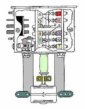
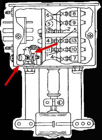
A 15 pin Jones plug for relay connections is located on the side.

"RF" connections to the Vacuum Contacts are on the side.
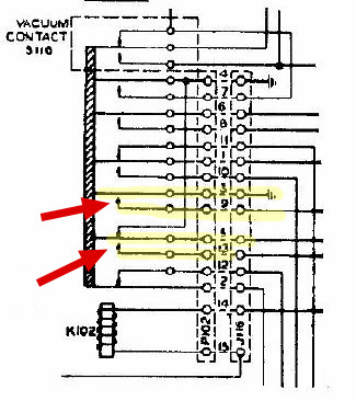
All
of the contacts are activated when coil K102 is activated by the
"Key Line". Relay contacts 5-13 and 3-9 provide the actual keying
of the RF stages. The Vacuum Antenna Relay (glass) contacts mounted on
the side of the relay (top of diagram) are also actuated.
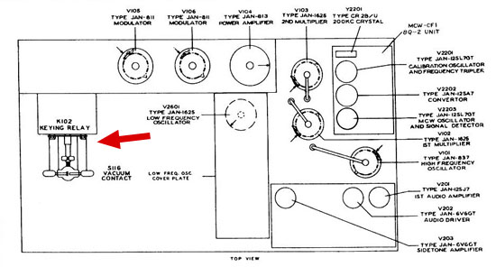
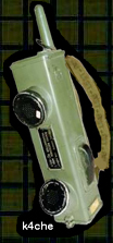
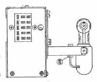
The main Keying Relay K102 and its Vacuum Contact is located on the top of the chassis. The relay can be disconnected and removed for maintenance.
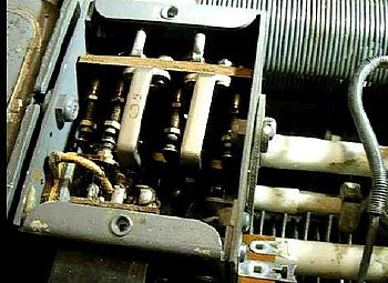
K102
with top cover removed
A
short video depicting the K102 relay action.
ART-13
K-102 Video.
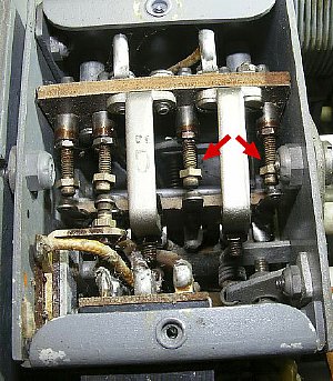
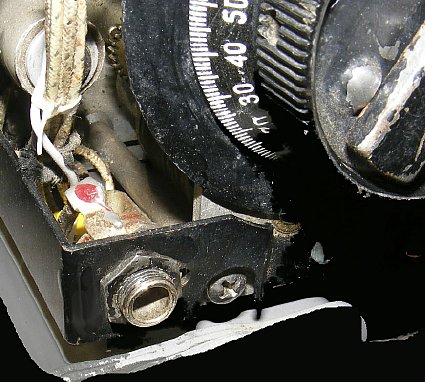
The internal contacts have adjustments for contact pressure and sequence.
K102
Relay Adjustment
There are also numerous "mechanical" adjustments for the delicate glass Vacuum Contact antenna switching relay. Only one of several adjustments is shown above.
Bypassing the K102 RT Relay Contacts for CW keying
![]() Key
the ART-13 R-F Carrier circuits on CW with a separate keying circuit.
During transmit all of the main RT relay contacts and the vacuum antenna
relay contact will remain in the transmit position reducing wear and tear
and best of all reduce the "clacking" noise.
Key
the ART-13 R-F Carrier circuits on CW with a separate keying circuit.
During transmit all of the main RT relay contacts and the vacuum antenna
relay contact will remain in the transmit position reducing wear and tear
and best of all reduce the "clacking" noise.
ART-13
CW keying.

Q.
I have been keying my ART-13 on CW for years and have never experienced
a problem.
A.
Good for you.
Q.
I have adjusted K102 on several of my transmitters and never had a problem.
All you have to do is read the manual.
A.
Good for you. I wish the manual would explain how to reduce the Clacking
during CW ops.
Q.
What about phone operation? Will modifications of the RF carrier keying
circuit effect it?
A. No. More details below.
Q. I hate the Clack Clack noise of the ART-13 when keying.
A.
Me too. Unmodified it is not my favorite CW transmitter.
Q. What's the big deal ? - if my relay fails I will just find another
one and plug it in.
A.
Good luck with that. Its not exactly "Plug and Play".
Q.
Are there relay adjustment instructions in the manual?
A.
Yes several pages for all versions of the relay.
Q.
Do I have to remove the relay to make the adjustments.
A.
It makes the process easier for several of the adjustments.
Q.
How do I power the relay if I remove it from the transmitter?
A.
Use alligator clips and power the relay coil via Jones connector 14 and
15.
Q.
What tools are needed to adjust the relay?
A.
Here is a link to several pages (Relay Adjustment) of the manual.

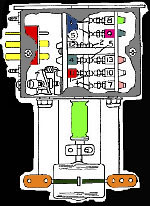
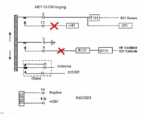
 All
models of the ART-13 use the same method of relay keying the RF carrier.
Simple keying circuit of the 813 screen voltage and the 837 oscillator cathode.
All
models of the ART-13 use the same method of relay keying the RF carrier.
Simple keying circuit of the 813 screen voltage and the 837 oscillator cathode. 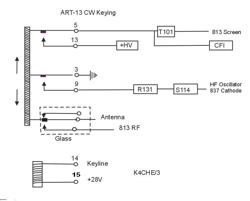
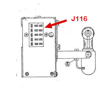
Click
to enlarge
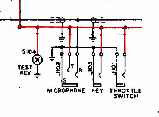
Arrows point to locations for possible external keying circuits. During unmodified CW operations the main R/T relay coil (K102) is keyed on and off via the "Keyline" for each dot and dash and all contacts are activated. The actual keying of the RF carrier is accomplished with relay contacts 5-13 and 3-9 and the Glass Antenna Contact.
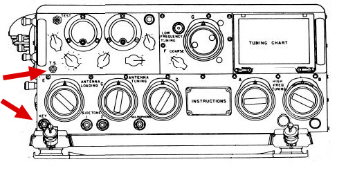
The
lower Jack J103 "Key" will be rewired for the new CW keying
circuit.
The
upper Throttle Switch (TS) Jack J101 wiring will remain intact.
After rewiring the Key Jack J103 for a alternate keying circuit the TS
Jack J101 can still be used for the original keying of the transmitter.
However the Key Jack circuit will need to be closed to provide a carrier.
Several ART-13 users have
installed a external RT switch using the TS jack. More info below.
J103 and J101 are standard 1/4 inch jacks on the "Keyline"..
813 Screen keying for the ART-13
 During bench testing small relays were used initially
for keying the RF carrier to test bypassing the main relay for keying..
The smaller relays were very quite when compared to the larger relay K102
that remained "closed" via the "Key" line.
During bench testing small relays were used initially
for keying the RF carrier to test bypassing the main relay for keying..
The smaller relays were very quite when compared to the larger relay K102
that remained "closed" via the "Key" line.
It helps to read all of the info below before going to the Mosfet keying circuits.
My first attempt at "Stealth" keying and to test the keying concept - - - I just keyed the 813 screen with a small relay. The smaller relay was very quite. No more Clack Clack of K102.
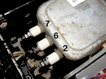
My first attempt at screen keying was to simply remove the 813 screen feed lead from terminal 7 of modulation transformer T101 and insert a small relay connected to the terminal.
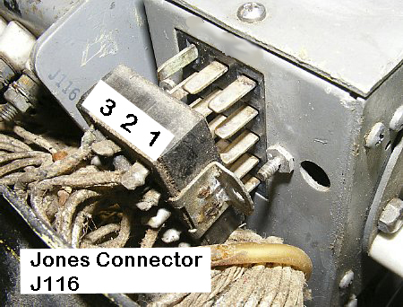
Later I removed the large Jones connector J116 from the side of the RT Relay for access to the wiring for the screen voltage terminal #13.
Relay
K102 uses a 15 pin Jones Connector
 High voltages are present on the Modulation
transformer and on J116.
High voltages are present on the Modulation
transformer and on J116.
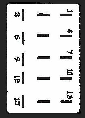
Jones
Connector Diagram
![]() When
keying just the 813 screen the HF oscillator ran
continuously. During key up conditions approximately
3/4 watt from the oscillator would bleed through the 813 (with no screen
voltage) circuit and feed the antenna via the ART-13 matching network.
This "Backwave" or small RF carrier could easily be heard in
the station receiver. During good HF conditions distant stations could
often hear the low power signal in the back ground. It
was very annoying to hear the constant carrier when monitoring on my receiver.
When
keying just the 813 screen the HF oscillator ran
continuously. During key up conditions approximately
3/4 watt from the oscillator would bleed through the 813 (with no screen
voltage) circuit and feed the antenna via the ART-13 matching network.
This "Backwave" or small RF carrier could easily be heard in
the station receiver. During good HF conditions distant stations could
often hear the low power signal in the back ground. It
was very annoying to hear the constant carrier when monitoring on my receiver.
![]() Another issue. When keying just the 813 screen separately via T101 terminal
7 (by passing the connector wiring) the CW sidetone circuit will
not be keyed and will be on continuously. I never use the sidetone to
monitor my keying so that was not a real problem.
Another issue. When keying just the 813 screen separately via T101 terminal
7 (by passing the connector wiring) the CW sidetone circuit will
not be keyed and will be on continuously. I never use the sidetone to
monitor my keying so that was not a real problem.
But
read on for Plan B.
The Key Jack 103 shell remains grounded to the chassis and the tip contact is rewired. The original "Tip" wiring was carefully removed and insulated. A single wire is connected to the tip contact and fed to the new keying circuit.
The Key Jack is grounded via its frame.
813 Screen and HF Oscillator Keying
Plan B: The
813 screen voltage and HF Oscillator Cathode keying were then tested by
using small relays to key circuits connected to Jones Connector terminals
9 and 13. The main Relay K102 contacts between 5 and 13 and 3 and 9 will
still be closed during transmit. In addition the Glass Antenna relay will
be in the transmit position and not Clack back and forth.
Any device used for keying the 813 screen voltage should be rated for
400 volts.
Keyer
circuits using Mosfits for the 813 screen and oscillator cathode will
be shown later but read on but for now I played with the small relays.
They were very quite.
Further info on using Mosfits instead of small relays for keying will be shown below.
Smaller "Quite" Relays can be used for keying the 813 Screen and if necessary the 837 Oscillator cathode. I used a "high voltage" vacuum relay (SPST) to key the 813 screen voltage and a smaller enclosed relay for the Oscillator cathode. I used this system for quite a while and it was very quite but later decided to continue on with a Mosfet keyiing system.
Q. Why use relays to eliminate keying a relay? It doesn't make any sense.
A.
You can barely hear these smaller relays when keying and they reduce the
maintenance on the main RT relay K102 contacts which will now remain closed
during transmit. In addition the glass antenna relay also remains closed
during transmit. However read on as solid state Mosfet keyers are presented
below.
Q.
Why not key the set with high voltage transistors or Mosfets?
A.
I used relays first as it was simple and to test the keying concept but
later switched to a Mosfet keying circuit. Circuits presented below.
Q.
What about the glass antenna relay? How do you key it for antenna change
over?
A.
K102 is constantly closed during transmit and that keeps the fragile glass
antenna relay switched to the transmit position.
Q. How to you keep K102 and the Vacuum relay closed during transmit?
A.
I used a simple toggle switch labeled Trans/Receive wired to a quarter
inch plug and inserted into the TS jack.
Q. Where do I plug in my key?
A.
The "Keyline" jack J103 (1/4 inch jack) is rewired to activate
the new keying circuit.
Q.
Why all this fuss? I am losing interest.
A.
You obviously do not work very much CW with the ART-13. The Clacking
of the main relay during CW is very distracting. In addition I dreaded
performing the K102 contact maintenance. The glass vacuum antenna relay
adjustment is scary.
Q.
I do not want to add mods that harm the original wiring of the set.
A.
All wiring is easily reversed to its original state.
Q.
What about my "Break-In" keying with the originial keying you
had a Break In system.
A.
It was a lousy system I do not miss it.
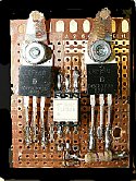
The two relays - - one for the 813 screen and the other for the HF Oscillator cathode are held in place with a piece of clear lexan. The small Screen keying relay is near the modulation transformer. Later the Mosfet keyers will replace the relays and occupy the same space.
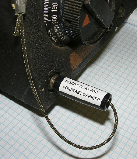
When Screen and Cathode CW keying circuits are used and phone operation is desired then use a "Shorting Plug" for a constant carrier. This restores normal PTT RF operations.Your microphone PTT will function and the TS jack will function. You can even insert a key into the TS jack and key with the original keying circuit if you miss the Clacking of the large relay.
813 Screen Mosfet Keyer
Click
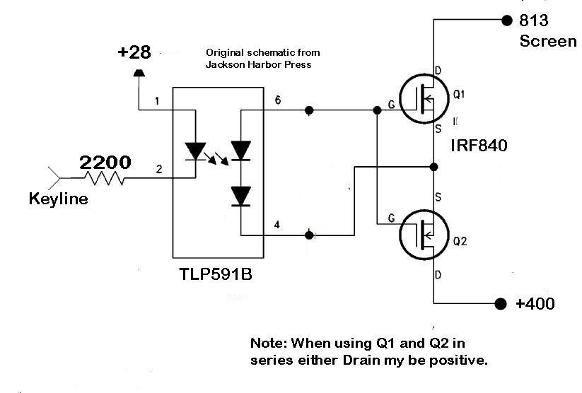
to enlarge - a Optical Mosfet "Keyer" schematic from "Jackson
Harbor Press."
The screen
voltage for the 813 can by keyed using Mosfets driven with a Photocoupler.
Complete
isolation of the high voltage is achieved.
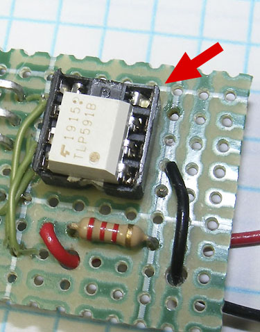
TLP591B Photocoupler is available from Mouser. A Keyer
board is available from Jackson Harbor Press,

Click
to enlarge
When using Mosfets in series the ratings are doubled.
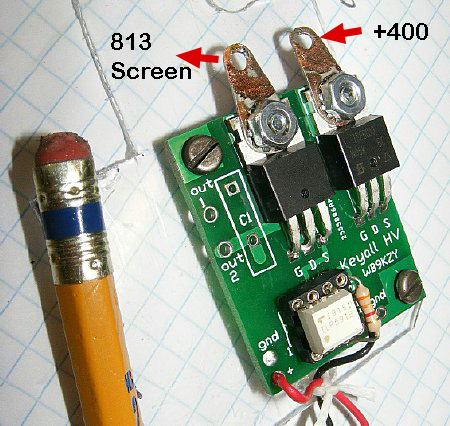
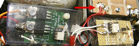
A
slightly modified "Keyall" Keyer board (Kit) by Jackson Harbor
Press
Jackson Harbor Press " WB9KZY" provides a dual Mosfet kit for keying. Initially a 3300 ohm resistor was used in series with the 28 volt power for keying the Photocoupler. On later circuits for other ART-13 transmitters I used a 2200 ohm resistor. A Max current of 25 mA is usually the recommended MAX current for the internal coupler LED and the minimum recommended is 3 mA. The 400 volt screen supply is connected to the two "Collector" tab terminals at the top. The polarity of the two tabs can be either way and positive voltage can be applied to either tab.
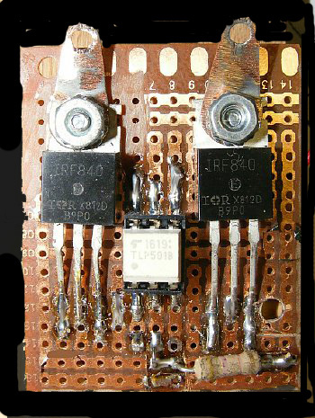
I
fabricated a keying board similar to the Jackson Harbor Circuit and it
is shown below. But the Harbor Press keying kit
is a bargain - you get a well designed board and all the parts.
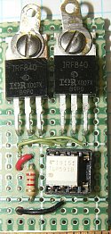
K4CHE
Ugly Screen Voltage Keyer
The Opticalcoupler / Dual Mosfet circuit is easy to fabricate on a Proto Board or Perf Board but the "Jackson Harbor Keyall" kit is a lot neater than my 20 minute creation shown above. I did wire up another version which is shown below.

813
Screen Voltage Keyer
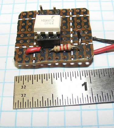
The specification sheet
for the HSR412 input current lists minimum and maximum current as 3 and
25 mA. Using Jackson Harbor info they use 1.25 as the LED voltage. 28
volts minus 1.25 =26.75. Using a current of 15 mA a resistor of
approx 1800 ohms would suffice. I had several 2200 ohm resistors in my
supplies. A 2200 ohm resistor would provide a current
of approx 12 mA - close enough for Government work.
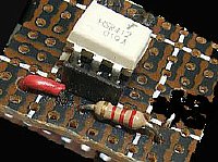
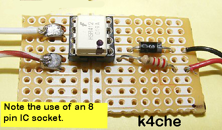
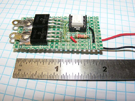
813
Screen Voltage Keyer
Another
perfboard (perforated board) version. Note the 2200 resistor for dropping
the 28 volts to the IC and the use of a 8 pin socket for the 6 pin IC.
Four (4) components - a quick project.
Q. Why not use a single mosfet?
A. You can but be sure and observe polarity. Dual mosfets give you higher ratings and you do not have to observe polarity.
Q. I don't have a 6 pin IC socket.
A. Use an 8 pin or take a larger socket and trim with sharp dikes.
Q. On the "Ugly" board shown above you put the components on the copper side instead of sticking the leads through the holes?
A. Sometimes I do things differently. A through hole version is shown above.
Q. What about a "Snubbing" circuit?
A. It was not deemed necessary.
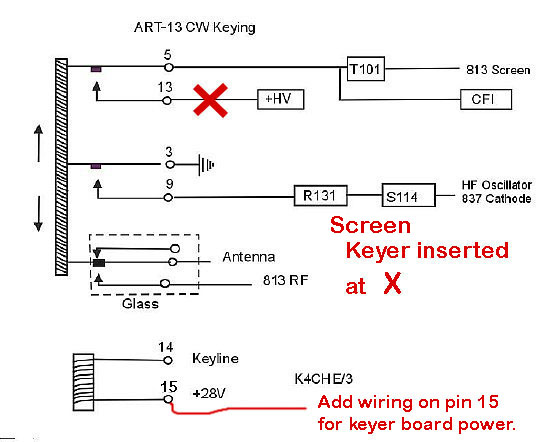
Disconnect Jones Connector pin 13 wiring and insert screen voltage keyer.
Use pin 15 for a 28 volt source for keyer boards. Do not remove original pin 15 wiring.
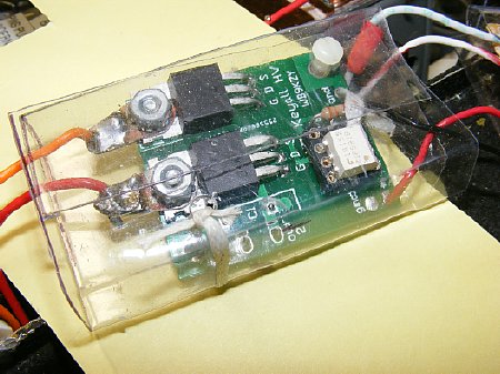
The screen keyer board can be enclosed in scrap sheet plastic.
![]() Use
a Heat Gun to bend the plastic scrap. Use a vise and clamp the plastic
while bendng. Scronge the plastic from a store package.
Use
a Heat Gun to bend the plastic scrap. Use a vise and clamp the plastic
while bendng. Scronge the plastic from a store package.
There is plenty of room for the "813 Screen" keyer next to the modulation transformer.
Oscillator
Cathode Keyer
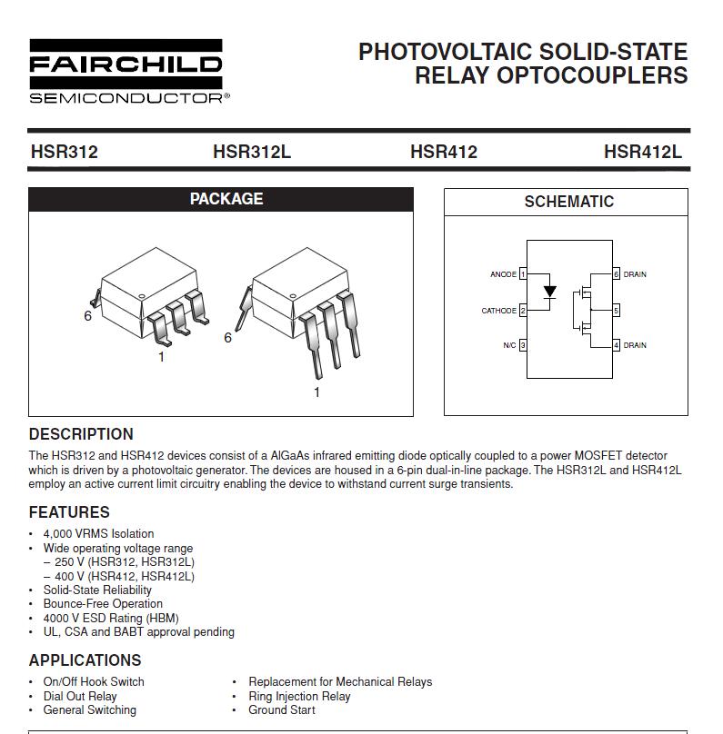
A keyer for the HF Oscillator cathode was constructed using an HSR412. Spec sheet shown below.
An 8 pin IC socket may be used - just use 6 pins.
Many Thanks to "Mr. Wizzard" - Al Klase N3FRQ for introducing
me to the HSR412 IC series. Its a great switch and has many applications.
ART-13
CW Keying of 813 screen and oscillator cathode
Insert the HSR412 keyer prior to pin 9.
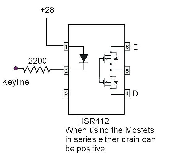
HSR412
HF Oscillator Cathode keying circuit.
When using the Mosfets in series either "D"
(Drain) can be the input regardless of polarity.
Click to enlarge.
The HSR412 has a 400V rating with excellent circuit isolation. It all most makes you believe in a "Free Lunch".
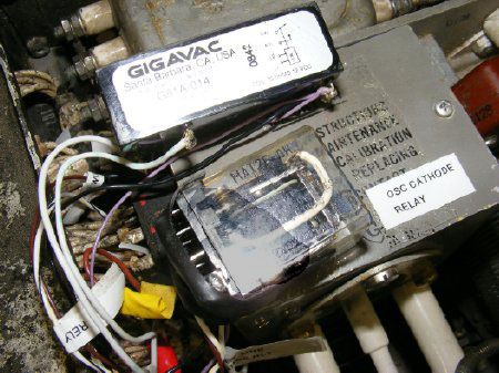
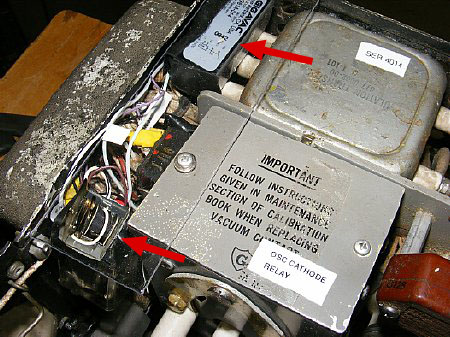
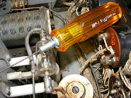
Loosen the relay mount and move the relay slightly and then you can have easier access to the female Jones connector J116.
For
Screen keying remove the connections (two wires) from Pin 13 of
the Jones Connector J116.
Connect the keyer
between the pin 13 wires that you removed and pin 13 on the Jones connector.
For Cathode keying remove the wire from Pin 9 (3rd row) and connect the HSR412 keyer between the wire you removed and the connector pin. Do not confuse pin "6" with pin "9".
Rear
view connection diagram of the Jones Connector.
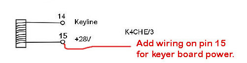
Power
for keying circuits can be obtained by "solder tacking"
a wire onto pin 15 but do not remove the pin 15 wire from the Jones
Connector.
Pin
13 wire information to confuse you: On the ART-13 original wiring there
are two wires connected to Jones Connector Pin 13. One wire connects
to Pin 1 of the main power connector J108 Dynamotor output (410V DC) and
the other wire wire feeds numerous circuits which consist of the R117,118,119,120
resistor combo which feeds Audio Amp, Low freq Osc, and HFO plate.
If you are curious you can ID the wires. Have fun tracing it out on the schematic. With the meter probe grounded the Pin 1 dyn will show continuity between the main power connector pin 1 and the other wire will exhibit the resistance of R117, 118 etc.
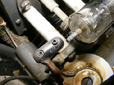
When moving the relay slightly for access to the Jones connector you may have to remove the end RF connections from the glass antenna relay.
Use the proper "Torx" tool for removal of the Glass Vacuum relay connector set screws.
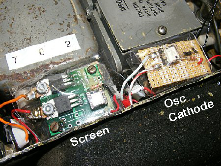
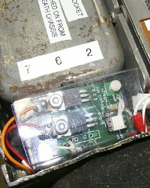
Plenty of room for the 813 Screen and HF Oscillator Cathode Mosfet keyers. The boards are enclosed in thin scrap sheet plastic scrounged from a store package.
I made a small wiring distribution board for the +28 volt power (Red) and J103 Keying line (Blk).
Plenty of room on a 2 inch perf board for the 813 Screen Voltage Keyer.
I ran out of 6 pin IC sockets. Used a 8 pin.
TLP591B is available from Mouser.
The HSR412 Cathode keying circuit can utilize a 1 inch perf board.
Q.
Will using two different and seperate keyer boards (813 Screen and Osc
Cathode) result in a keying sequence problem.?
A.
No sequence problem was noted since they both use the same short keying
line. "Unmodified and Modified" Oscilloscope video and photos
are presented below.
Q.
Why use two different board designs why not just use another 813 Screen
Voltage board to key the Osc Cathode ?
A.
You can - but for the Osc cathode I like the smaller HSR412 board better.
Q.
I've read all your info. Are there any other simple CW modifications by
others?
A.
Not very simple but you can go to I0JX's web page and down load his paper
on the ART-13. Link below. In additon the "CQ Surplus Conversion
Handbook" has info.
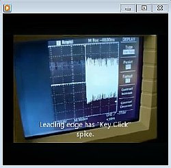
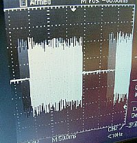
Click her for Scope video of ART-13 Standard Keying without modification.
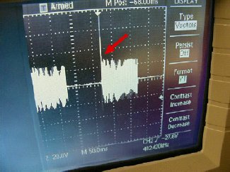
ART-13
Standard Keying no Modification.
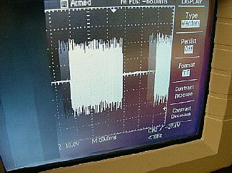
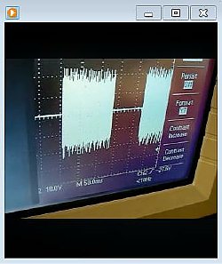
ART-13
Modified keying with Mosfets.
The above photos appear to indicate
that 'Mosfet Keying" of the 813 Screen and Oscillator Cathode on
the Test transmitter provides a cleaner pattern. However the ART-13 relay
K102 contact sequence could have possibly be "Fine Tuned" for
a better pattern.
The same transmitter was used for all testing.
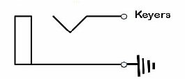
Shorted
plug inserted into Key Jack
During Phone Operations insert a shorted plug for normal PTT and a constant carrier.
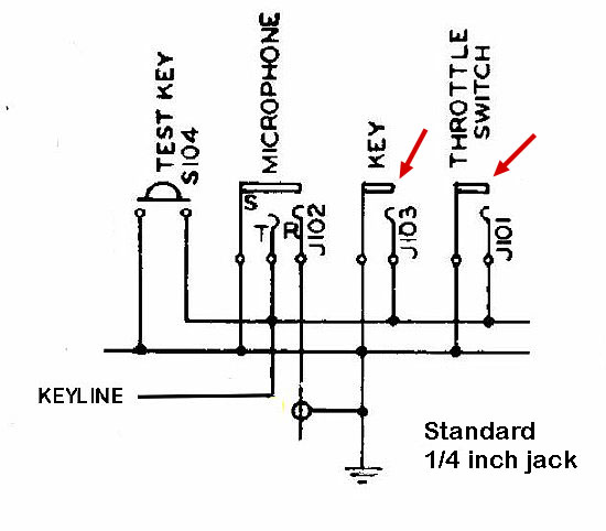
Note that the Throttle Switch "TS" jack is on the same keying line as the Key and Microphone.
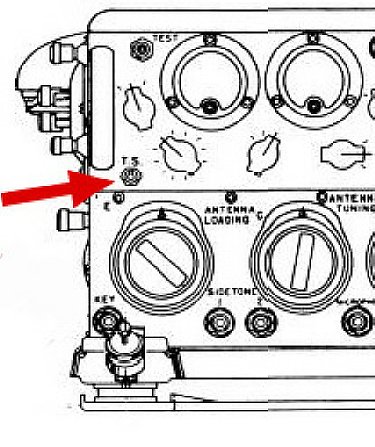
TS
(Throttle Switch) jack
The
TS (Throttle Switch) is a Standard 1/4 jack
can be used for an easy connection for an external TR switch. When the
circuit is closed K102 goes to the transmit position. You can mount an
external switch at a convenient location at your operating position. The
upper panel mounted Test Key switch still functions and was not changed.
Remember that if you get home sick for the relay
Clack Clack sounds you can always close the Mosfet RF keying circuits
with the "Shorted Plug" and then insert your key in the TS jack.
"That's about all I know bout ART-13 keying."
Return
to K4CHE Index.
ART-13
CDA-T Info