| ART-13 CDA-T( Info on crystals, LF ops, filament circuits, extended range notes.) |
 This page on the ART-13 contains information and techniques
dedicated to the ART-13 transmitter. This web page assumes that the reader
has possession of the ART-13 A amd B manuals. The Philco "Training
Manual is also a valuable source of info.
This page on the ART-13 contains information and techniques
dedicated to the ART-13 transmitter. This web page assumes that the reader
has possession of the ART-13 A amd B manuals. The Philco "Training
Manual is also a valuable source of info. Perhaps some of my adaptations or mods offend those that want a "perfect" radio. My goal is to move the radios off the shelf and into hobby type operation.
Index Click to Navigate
CDA-T
Simple Installation
Crystals
Tuning
837
Filament Circuit
Low
Frequency
Extended
Range Mod
CDA-T
Simple Install
The
material presented below describes a "Simple Installation" of
the CDA-T module.
 The
"Simple Installation" has limited channels etc. but will provide
you with a working CDA-T chassis. Those wanted a perfect 20 channel installation
can skip this part.
The
"Simple Installation" has limited channels etc. but will provide
you with a working CDA-T chassis. Those wanted a perfect 20 channel installation
can skip this part.
The Low Frequency section which is "Plug and Play" has 4channels and does not require any modification of the transmitter. - - just plug it in.
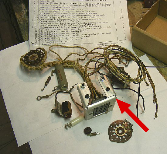
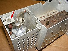
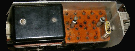
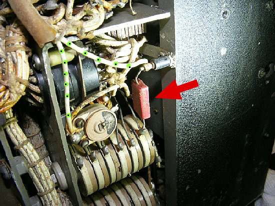
Original
Installation Parts that were removed. The Jones Connector Bracket (Red
Arrow) was not supplied in the original kit and has to be fabricated.
The original installation required extensive disassembly of the ART-13. Estimated man hours for the CDA-T original installation was 15 and did not include time utilized for fabrication of the "Bracket".
The parts in the photo above were removed from a ART-13B.
Note that the large 15 pin Jones connector is mounted to a heavy duty
bracket. The bracket was not supplied with the original kit but you were
provided detailed engineering drawings - you will need to possess good
sheet metal skills and equipment or a machine shop to fabricate the bracket
out of .065 Aluminum. On
the "Simple Installation" we eliminated the bracket and most
of the parts.

Q.
On the "Simple Install" what are the operational differences
between the original install and the "Simple Install" ?
A. You only get two crystal positions. You can not assign a crystal position to a ART-13 channel.
Q.
How do I turn on the CDA-T chassis after the simple install?
 A. Switch from VFO to XTAL.
Q. What has to be done to modify the ART-13 to use the Low Frequency portion of the CDA-T chassis?
A. Nothing. Plug and Play. Just plug it in. More info later.
Q. With only two crystal channels why bother.
A. The simple install gives you a chance to play with the CDA-T. Plus you get LF ops if it is installed on the CDA chassis . Another bonus is it fills the blank hole in the front of the ART-13 and the on board resistor network on the CDA-T provides the proper filament ballast for the HF Oscillator 837 filament circuit. How many channels do you need anyway?
Q. I need all of the twenty (20) channels.
A. You are SOL.
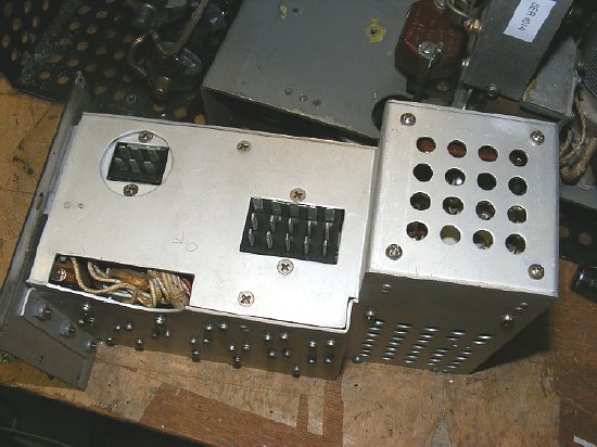
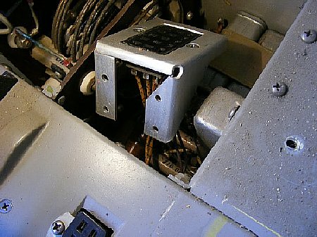
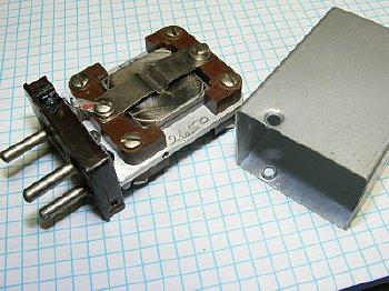
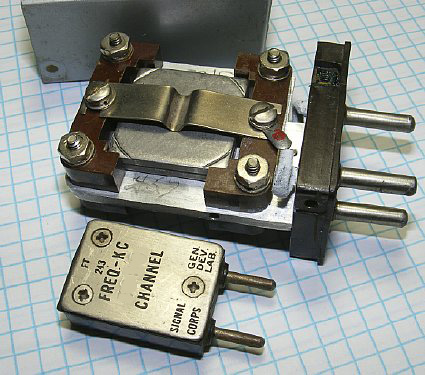
CDA-T
module bottom view.
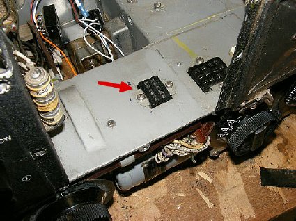
The CDA-T chassis utilizes Jones connectors. The smaller 6 pin male connector plugs into the same chassis connector (6 pin female) P401 on the ART-13 that was installed for the low frequency oscillator. The larger 15 pin connecor needs a socket installed on the transmitter or do the "Simple" install.
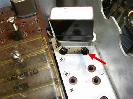
The
P401 6 pin Jones connector was installed on all transmitters. See next
photo.
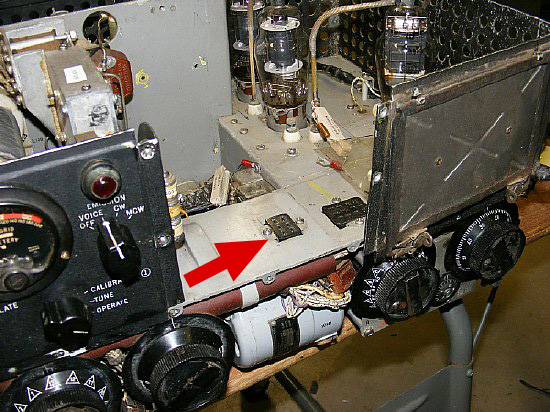
Red
arrow: P401
The
6 pin male Jones Connector P401 that was installed for the LF Oscillator.
The LF VFO oscillator
( 0-16/0-17) was simply plugged in and the Low Frequency RF output connected
via a short wire to the ceramic feed through. The ceramic feed through
can been seen in the back ground next to a 1625 multiplier tube.
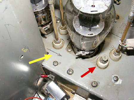
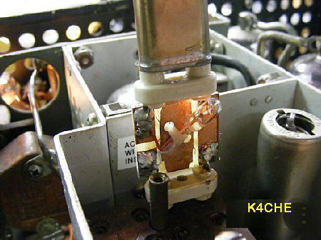
Ceramic
Feedthrough Connector (Red Arrow)
The Low Frequency Feed
through (red arrow) was installed on all ART-13 transmitters. The feedthrough
allowed direct connection from the Low Frequency Oscillator output to
the grid circuit input of the 813.
![]() When trouble shooting and changing tubes etc. observe the orientation
arrows painted on the chassis next to the vertical posts that connect
to the tube caps. Do not reverse the cap connections.
When trouble shooting and changing tubes etc. observe the orientation
arrows painted on the chassis next to the vertical posts that connect
to the tube caps. Do not reverse the cap connections.
Jones
connector Bracket manufactured to specs. Removed from a "Parts Only"
transmitter.
I put bracket fabrication and the disassembly
of the transmitter for the installation of the bracket in the "To
Hard To Do Box".
![]() Here
is the original scan of the CDA-T Crystal Control Conversion developed
by Pan American Airways and manufactured by Gables Engineering in the
years 1948-1949. The original scan was made available by WA5CAB. Many
thanks to Robert who has helped many military radio and vehicle collectors
with his sage advice and vast inventory of parts. He also has reprints
of military manuals that are of the highest quality and my wife says they
smell good !
Here
is the original scan of the CDA-T Crystal Control Conversion developed
by Pan American Airways and manufactured by Gables Engineering in the
years 1948-1949. The original scan was made available by WA5CAB. Many
thanks to Robert who has helped many military radio and vehicle collectors
with his sage advice and vast inventory of parts. He also has reprints
of military manuals that are of the highest quality and my wife says they
smell good !
CDA-T Conversion 1-Jan-50 WA5CAB
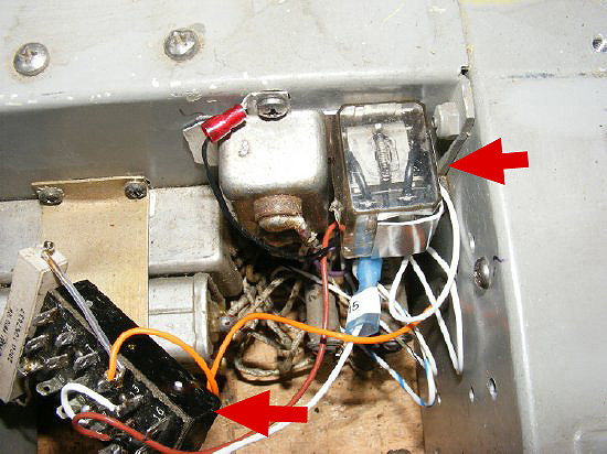
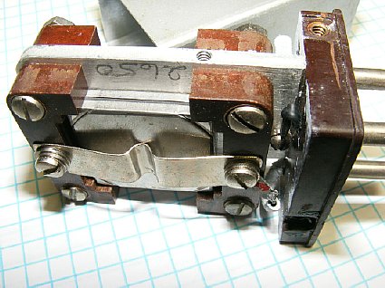
CDA-T
Jones Connector and Relay.
The Simple Install - just wire up 4 pin connections on the 15 pin Jones connector and install a relay. It takes more time to describe it than to do it. The 15 Pin Jones connector is not mounted on a chassis bracket and is just plugged into the bottom of the CDA-T chassis.
Q. Why not just plug in the CDA-T module and insert a crystal?
A. The Gables Engineereing CDA-T kit required transmitter extensive rewiring, sheet metal work, wafer switch modifications and extensive disassembly of the transmitter. "There is no free lunch".
Q. With the "Simple Modification" what features are available"
A.
VFO or XTAL . You
can select two crystal positions A or B.
Q. I don't want to modify my CDA-T module as it is used on another of my transmitters.
A. You do not have to modify the CDA-T module. You will only add wiring to the ART-13.
Q. What parts do I need for the Simple Installation?
A. A 15 pin female Jones connector or use Push On wire terminals. A DPDT relay, two resistors
Q. Where do I find the 15 pin Jones connector.
A. Where else but ePay.
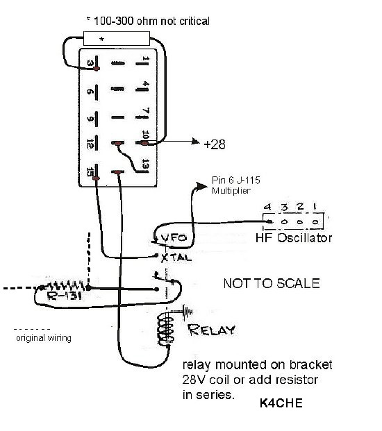
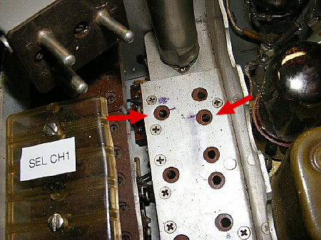
The
Simple Installation
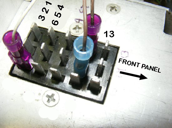
The original single wire running to pin 4 for the HF oscillator is disconnected and the end insulated. Then connect Pin 4 with a new wire to a upper contact on the DPDT relay. Run another wire from pin 6 (tack solder) of the multiplier connector J115 to the armature of the "New" DPDT relay.
Connect the other contacts of the relay to R-131. Leave existing wiring to R-131 in place.
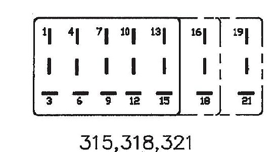
Jones 15 pin female connector is a female stock #315. However if you find a 18 pin connector (318) in your junk box that will also fit the 15 pin male on the CDA-T chassis. "Improvise-Adapt-Overcome"
Push On terminals can be used instead of a Jones Connector.
HF Oscillator terminal 4. The original wire to terminal 4 is unsoldered and the end insulated. Connect a new wire from Terminal 4 to the upper contact of the DPDT relay. Later if desired you can reverse the process to return the transmitter to its orginial wiring.
Tack
solder a wire to pin 6 and connect to the relay.
Pin 6 connection of the J115 multiplier connector (female side). The original installation required pulling the entire multiplier unit. In the "Simple" installation we leave the Multiplier unit in place and just tact solder on a wire to pin 6 while leaving the original wire to pin 6 intact. The original wiring from pin 6 went to Terminal 4 of the HF oscillator which was disconnected in the previous step.
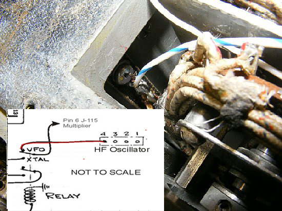
Here are the original instructions:
CLICK
to enlarge
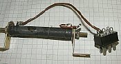
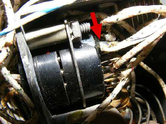
The
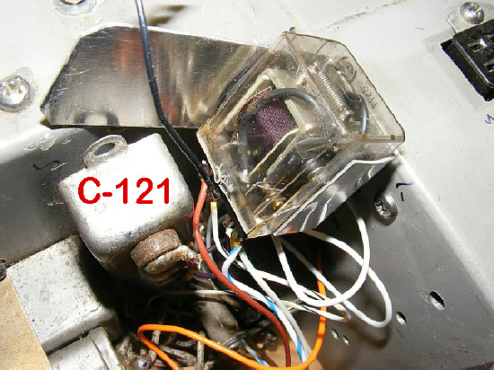
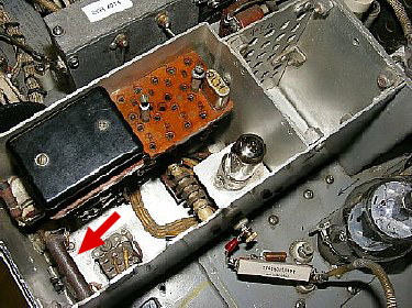
DPDT relay is mounted with a small bracket behind C121.
R131 is mounted on the chassis below.
The DPDT relay and fabricated bracket are mounted under one tab of C121. The R131 original wiring will be left intact and new wires from each end of R131 will be connected to the new DPDT relay. The DPDT relay disables R131 when switching to XTAL as the 6AQ5 does not need a cathode resistor.
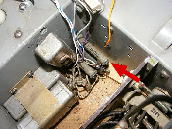
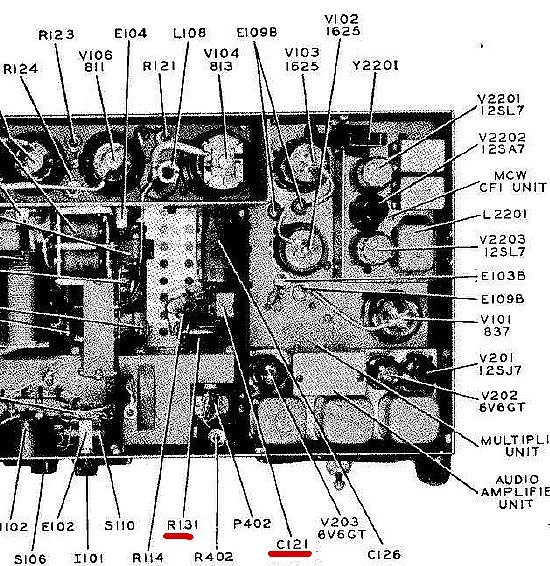
R131
Red Arrow
R131 connections to the relay can be easily wired. Connect wiring from the upper and lower contacts of the DPDT relay to each end of the resistor. Do not remove any exsisting wiring from R131.
Q. Why short out R131 with the relay ?
A. R131 is the cathode resistor for the 837 oscillator. The 6AQ5 in the CDA-T does not require a cathode resistor so the relay provides a short across R131 which then provides a direct ground for the 6AQ5 cathode.
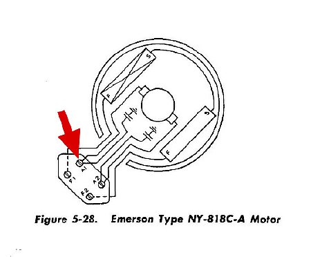
Terminal
A1 on the motor was used as a source of +28.
Connect a wire from this terminal to pin 10 of the new female 15 pin Jones
connector to provide power to the CDA-T chassis.

The
6AQ5 high voltage plate connection for the CDA-T oscillator is made via
a 6K resistor and a 25 pf capacitor in parallel to the vertical post of
the 837 spring lead plate connection.
Use
a terminal and a knurled nut for easy removal from the ceramic feed through
terminal of the CDA-T chassis.
Q. I don't have a 6K 10W resistor or a 25pf capicator
A. Try a 5K and 30 pf as the circuit is not very critical.
Q. The connection for the resistor/capicator assembly is to the plate lead "post" of the 837 oscillator. Will this CDA-T resistor/capicator connection load down the output of the 837 oscillator? When I am not using the CDA-T do I have to disconnect the resistor/capicator network?
A. No. Bench testing of 813 Grid Drive/Output was conducted with and without the resistor/capacitor connection to the CDA-T. No noticeable degradation in output was noted.
Q. I don't have a knurled nut.
A.
Visit your hardware store.
HC-6 crystals or an adapter. Crystal current check below.
 Ham Bands 1-4 the first frequency multiplier acts
as a doubler. Use the formula Carrier Frequency divided by 2. Example
frequency 3558 Kc requires a crystal of 1779 kcs. Band 7 and 8 the frequency
multiplier acts as a tripler. Example 7040
requires a crystal of 2346.6.
Ham Bands 1-4 the first frequency multiplier acts
as a doubler. Use the formula Carrier Frequency divided by 2. Example
frequency 3558 Kc requires a crystal of 1779 kcs. Band 7 and 8 the frequency
multiplier acts as a tripler. Example 7040
requires a crystal of 2346.6.
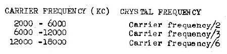
Example:
 Band
3 crystal frequency = Carrier Frequency/2
Band
3 crystal frequency = Carrier Frequency/2
6AQ5
Crystal current Check.
Using an current jig with a 30 mA test bulb the 6AQ5 crystal oscillator circuit drew less than 10 mA. The older Military Surplus HC-6 crystals (CR-18 specs) should not be a problem.
The small bulb is wired in series with one pin of the
crystal holder. The bulb will change/soften
the CW keying characteristics.
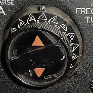
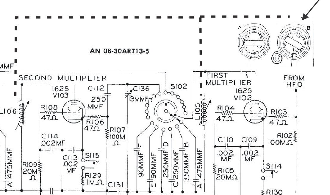
There
are no adjustments or tunable circuits on the CDA-T chassis for HF ops.
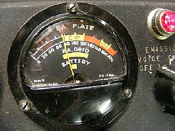
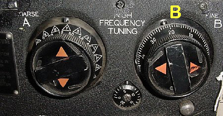
Peaking of the PA Grid is accomplished using "Control B" which tunes L105 and L106. As a general rule set "B" via the frequency tables to the multiplier output frequency and then peak. The setting does not have to be exact and only approximate as you will be using Control B to peak the CDA-T output.
When using the CDA-T chassis. Peak Grid using control B which is mechanically coupled to L105 and L106
During CDA-T HF ops Peak Grid using control "B"
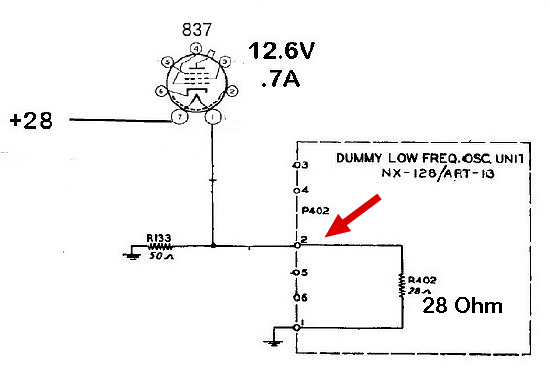
837 Oscillator Filament Circuit
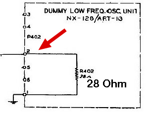
Schematic
Dummy Low Frequency Osc Unit
The 837 HF Oscillator filament (12.6 V at .7A ) is in series with a resistive network consistiing of R-133 and with ever module or chassis network is connected to pin 2 of P402.
Without
a load on pin 2 of P402 the filament voltage for the 837 will be too low.
The "Dummy Low Freq Osc Unit" (shown later) consists of a 28
ohm resistor connected to pin 2 and ground. The "Dummy Low Freq Osc
Unit" was utilized when low frequeny operations were not utilized.
Suggested
Proper loads for Pin 2:
1.
Dummy Low Frequency Osc Unit.
2.
O-16 and O-17 Tunable Low Frequency Oscillator Units.
3.
CDA-T Crystal Controlled Unit. (Requires modification of transmitter)
4.
Home brew plug in unit using a 28 ohm resistor.
5.
A home brew light bulb load. (Shown below)
P402
P402 is a 6 pin Jones female connector and is standard on all ART-13 transmitters. Orginally installed for the Low Frequency Oscillator O-16 or O-17.
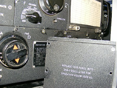
The
"Dummy Panel" looks great and plugs into the P402 chassis connector
and fills the vacant hole in the front panel if a LF Oscillator is not
installed.
R402 on the "Dummy Panel" is a 28 ohm power resistor - when plugged into P401 on the ART-13 chassis it provides the proper load for the 837 filament circuit.
CDT-A
chassis without a LF Oscillator. A 28 ohm resistor is mounted at
the end.
The CDA-T chassis without the 1625 low oscillator section has a internal 28 ohm resistor. The 6AQ5 filament is on a seperate circuit.
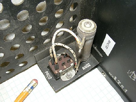
A
bench test jig for P402 which is used to replace the "Dummy Panel"
or the other plug in Low Frequency Oscillators . The Resistor is grounded
at one end to the mounting bracket the other end connected to pin 2 of
the Jones connector. Suggested resistance is 28 ohms.
The
original R402 was 28 ohms.
![]()
Be
careful when experimenting with different resistor loads in place of "R402".
Monitor the filament voltage carefully to prevent damage to the 837 tube
12.6Volt filament.
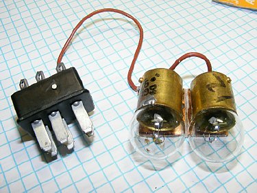
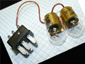
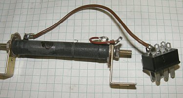
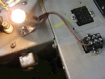
A pair of Type 97 bulbs (12V) can be wired in series and used as a close substitute for a 28 ohm resistor.
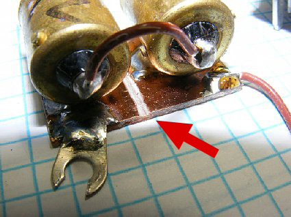
Light
bulb substitute for the 28 ohm resistor.
The bulb bases are soldered to a blank copper clad board (PC Board) with a grove to seperate each bulb as they are wired in series. The board is grounded to the chassis.
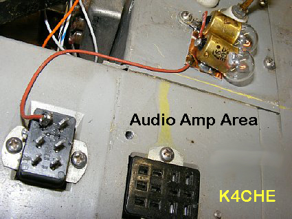
ART-13
chassis with "Audio Amp" removed.
The
double bulbs in series glow at a reduced brillance but provide a resistive
load close to 28 ohms.
"Improvise-Adapt-Overcome"
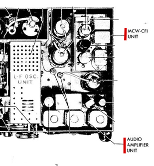
 The ART-13 can produce a basic RF carrier with the MCW
and Audio Amp removed.
The ART-13 can produce a basic RF carrier with the MCW
and Audio Amp removed.
Pin 2 needs approximately 28 ohms connected and grounded.
A
single 12 volt bulb resulted in a filament voltage to the 837 of around
11 volts. The 837 oscillator had output with the 11 volts but drive may
be reduced depending on your tube.
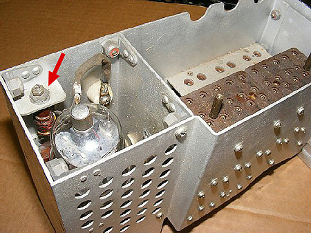
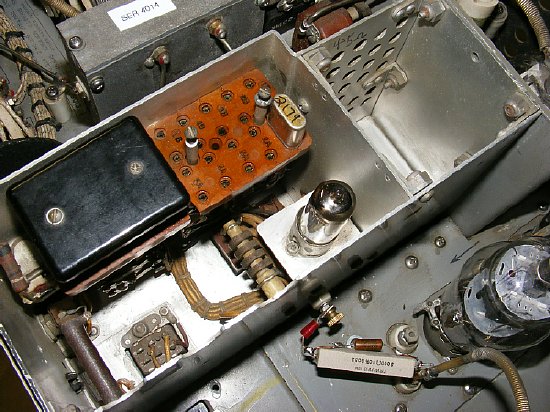
CDA-T
Low Frequency Oscillator.
Shown above is the CDA-T with the Low Frequency oscillator installed using a 1625 tube. The 1625 plate tuning coil for LF is located on a bracket located in the upper left corner.
![]() High voltage is present on the coil and the plate cap of the 1625.
High voltage is present on the coil and the plate cap of the 1625.
CDA-T
chassis without the Low Frequency Oscillator installed.
The CDA-T plug in chassis came in two versions with and without the Low Frequency section.
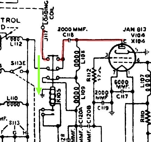
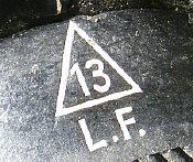
Low
Frequency RF path. K105 is energized when you select Position 13 on Control
A.
During Low Frequency Operation K105 is energized and the 813 RF output is fed direct to J117 "Load Coil" push terminal connector on the side of the transmitter. An external tuning network and load must be connected to the "Load Coil" terminal located on the side of the transmitter.
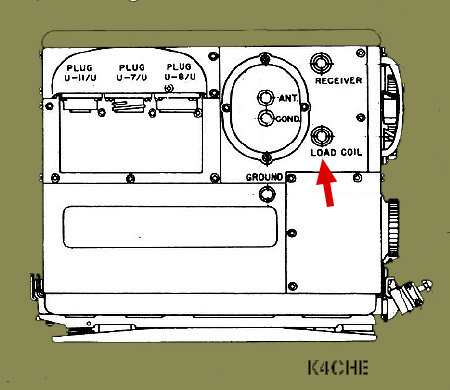
A "Load" must be attached to the "Load Coil" J117 terminal during testing of the LF range.

CDA-T
with Low Frequency Oscillator- tube is a 1625.
The
CDA-T Low Frequency Oscillator is active when the chassis is plugged into
P402 and is plug and play. No modifications to the ART-13 are necessary.
The CDA-T chassis (all versions) provide the proper resistive load resistor
for the 837 filament circuit.
 Remember you must be in the L.F. Position
on Control A - this will activate relay K105 and connect the 813 output
to the "Load Coil" terminal.
Remember you must be in the L.F. Position
on Control A - this will activate relay K105 and connect the 813 output
to the "Load Coil" terminal. 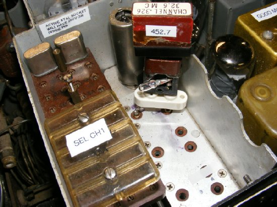
Crystal
current check using a minature 30 ma bulb.
The CDA-T low frequency oscillator requires a crystal mounted in a FT-249 (3 pin) holder or similiar. A Crystal Current check on the 6AQ5 circuit was accomplished and the current is well below 10 ma. If the 30 ma bulb glows bright you are in the critical zone and are subject to crystal damage.
Only
two pins are used on the FT-249 socket.
The FT-249 crystal holder is sort of rare. An adapter of sorts can be fabricated. On other equipment the FT-249 holder often had two crystals installed for two channels. On the CDA-T chassis only one crystal position (two pins) are utilized.
Robert Downs : "There are several nomenclatures for the holder. FT-249 is one. The TCS used one, Navy Type Nr COP-40068-A, CHF-40130 and COP-40130-B that I know of. Despite the fact that neither the receiver nor the transmitter ever had but one crystal in it and there was no facility to select the 2nd crystal anyway."
Robert WA5CAB has FT-249 crystal holders in stock but does not have any
frquencies below 1500 kcs.
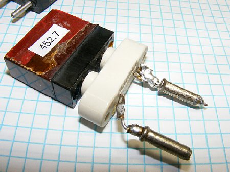
FT-249 Crystal Holder
The FT-249 holder has provisions for two (2) crystal blanks - one on each side.
The crystal blanks in the FT-249 are fairly large. The holder is easy to disassembly for removal of the blank for frequency etching.
A quick adapter can easily be fabricated in 10 minutes. This one is so ugly it may have only taken 5 minutes.
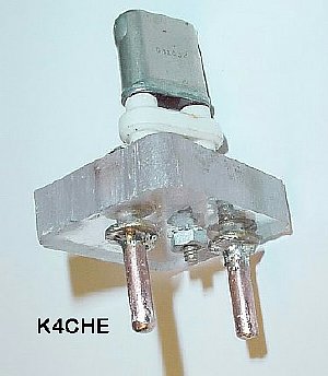
Another version of a adapter.
Crystal
Adapter in the Low Frequency #1 socket Position.
The adapter only uses 2 pins. Approximately 150 volts will be present on the outboard pin when the socket is activated by the CDA-T front panel. The adjacent socket pin is not used
During
Low Frequency Ops internal tuning networks on the ART-13 are bypassed
and the the 813 output is fed straight through to the side "Load
Coil" terminal. The ART-13 does not have any internal provisions
for matching the Low Frequency RF output.
Connect a Low Frequency Antenna Tuning network to the Load Coil terminal.
![]() Do not operate the transmitter in Low Frequency mode
without a "LOAD". Extremly high RF voltages are present. K105
contacts may be damaged.
Do not operate the transmitter in Low Frequency mode
without a "LOAD". Extremly high RF voltages are present. K105
contacts may be damaged.
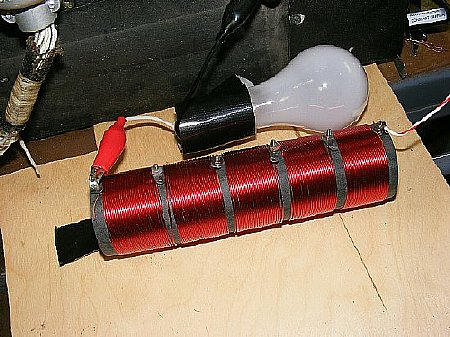
A temporary low frequency load for the bench can be constructed. Use a 300-400 uH coil in series with a light bulb. It won't be a perfect match but will allow partial loading of the light bulb. Get a 2 inch size PVC and wind turns until you get tired.
Click
to enlarge.
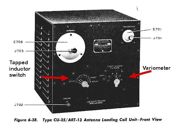
The CU-25 is easy to use and will match a variety of loads
Fixed capacitors, a tapped coil, and a variometer.
Click
to enlarge.
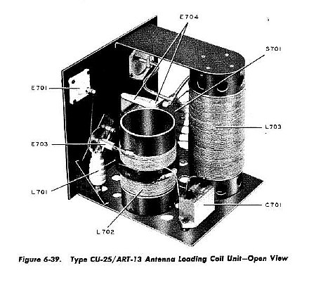
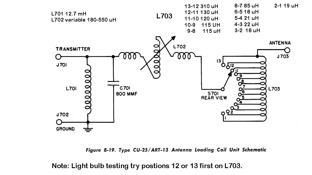
L701
is a 12.7 mH choke and is used to bleed off static electricy.
L702
is a Variometer and tunes 180 to 550 uH.
L703
is a tapped inductor with variable taps varing between 18 and up to 310
uH
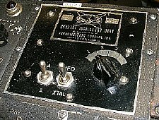
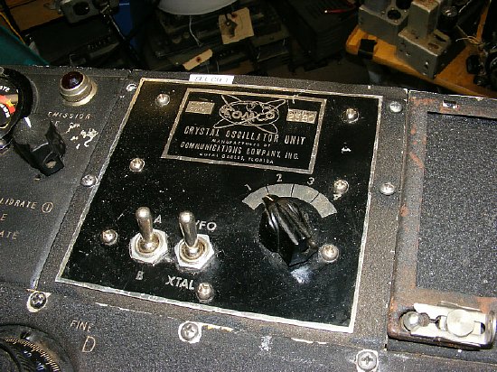
Extended Range Switch Modification
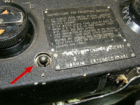
Extended
Range Switch
Most installations of the CDA-T kit included the Extended Range mod for the ART-13 multiplier section. The toggle switch was used to add a capacitor to the multiplier for lower frequency operation.
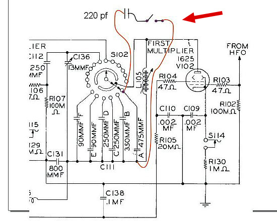
The Extended Range Switch adds 220 pf to the position "A" trimmer (475pf ) to lower the frequency coverage. The 220 pf capacitor lowers the tuning range of the position "A" multiplier section from 2000Kcs down to 1670 Kcs.
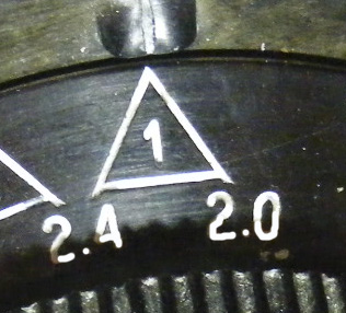
![]() When
selecting "Extended Range" and Position 1 (2.0 2.4)
and you are operating in the High Frequency "VFO" mode selecting
the "Extended Range" will effect the grid drive. During normal
operations when the CDA-T module is not being utilized make sure the switch
is OFF.
When
selecting "Extended Range" and Position 1 (2.0 2.4)
and you are operating in the High Frequency "VFO" mode selecting
the "Extended Range" will effect the grid drive. During normal
operations when the CDA-T module is not being utilized make sure the switch
is OFF.
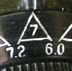
![]() Same
problem occurs when selecting postion 7 (6.0 - 7.20 ) as the wiper
on S102 selects trimmer capicator A again.
Same
problem occurs when selecting postion 7 (6.0 - 7.20 ) as the wiper
on S102 selects trimmer capicator A again.
![]() Disconnect the Extended Range toggle switch unless operations are necessary
in the lower ranges as sooner or later you will forget to check the switch
in the Off position.
Disconnect the Extended Range toggle switch unless operations are necessary
in the lower ranges as sooner or later you will forget to check the switch
in the Off position.
One end of the 220 pf capacitor is connected to the first 475 pf ceramic trimmer(A) . When the front toggle switch is placed in the ON or UP position the other end of the capacitor is connected to RF ground.