T-195
"FSK IN / MO" Operations
4 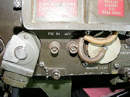
 By
switching cables located in the upper section of the T-195 you can connect
the front panel FSK IN and MO connectors (BNC's) for Frequency
Shift FSK operations with the MD-203 Modulator. On most transmitters the
front FSK IN and MO (BNC) connectors are inoperative and
not connected to any transmitter stages.
By
switching cables located in the upper section of the T-195 you can connect
the front panel FSK IN and MO connectors (BNC's) for Frequency
Shift FSK operations with the MD-203 Modulator. On most transmitters the
front FSK IN and MO (BNC) connectors are inoperative and
not connected to any transmitter stages.
![]() Do not connect the MD-203 modulator until you have verified
the status of the front BNC connectors. A simple check is to use an ohm
meter and check for continuity between the two FSK IN and MO
connectors on the front of the T-195. A direct short indicates
that they are connected to each other (stowed) and can not be used
for the MD-203. The cables must be reconfigured for MD-203 FSK ops.
Do not connect the MD-203 modulator until you have verified
the status of the front BNC connectors. A simple check is to use an ohm
meter and check for continuity between the two FSK IN and MO
connectors on the front of the T-195. A direct short indicates
that they are connected to each other (stowed) and can not be used
for the MD-203. The cables must be reconfigured for MD-203 FSK ops.
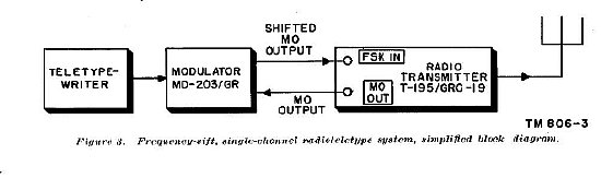
The T-195 MD-203 Modulator
utilizes the "FSK IN" and "MO" BNC connectors.
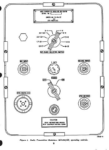
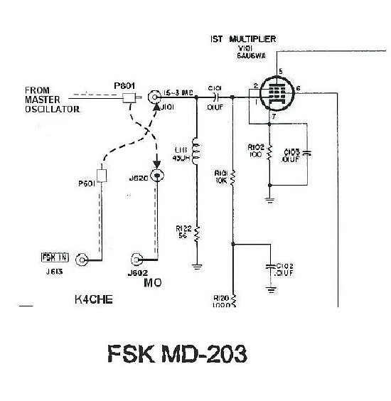
MD-203 Modulator
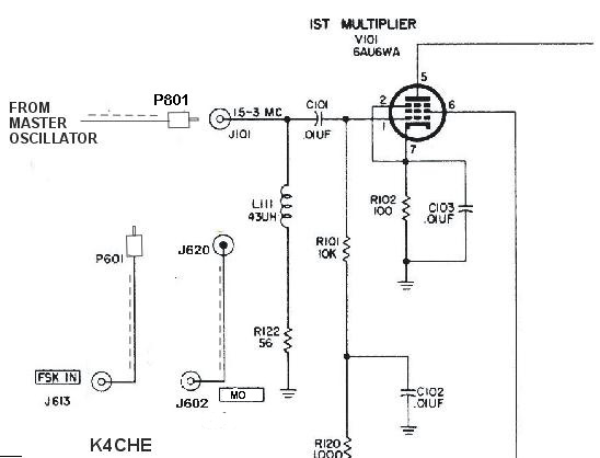
Figure 1-10 from TM 11-5820-335-35 with a few changes.
The front FSK IN and MO (BNC) connectors
are depicted at the bottom of the sketch.
FSK configuration
for the MD-203: Plug P801 into J620. Connect P601 into
J101.
NON FSK: P801 is plugged in J620. The cables are not used.
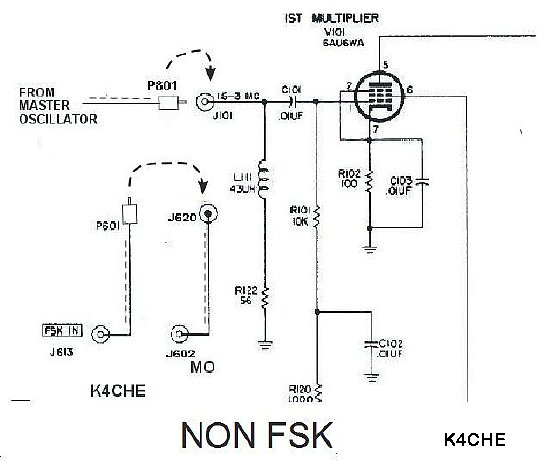
Most transmitters will have the cables stowed in the Non FSK position and the T195 transmitter Master Oscillator feeds the 1st Multiplier direct. The front BNC's are connected to each other. The MD-203 modulator can not use this configuration.
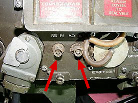
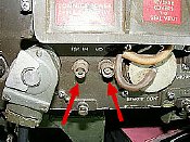
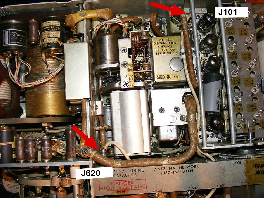
FSK IN and MO BNC Connectors
CLICK
to enlarge
Arrows point to cables plugged into female connectors
J620 and J101.
J620 mounted on the transmitter chassis feeds the front MO BNC connector. J101 is located on the Multiplier Chassis.
Female chassis connector J620 is mounted on the chassis near the front above the "Antenna Tuning Capacitor"
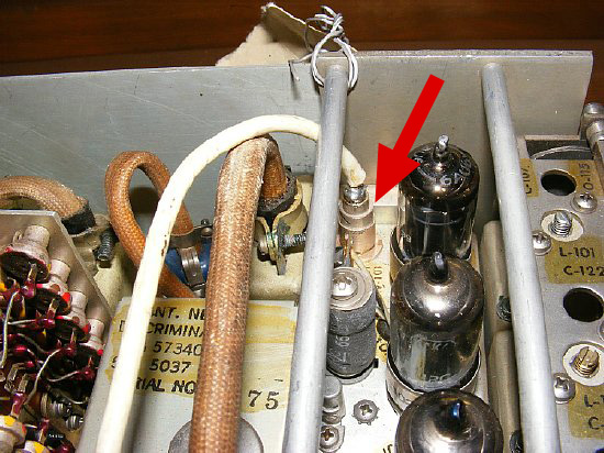
J101 is located on the rear of the Multiplier chassis.
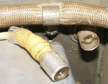
Connectors
are coaxial and are held in place by a friction fit.
![]() Connector wiring is fragile. Grasp the cable and
the top edge of the connector when plugging in or unplugging.
Connector wiring is fragile. Grasp the cable and
the top edge of the connector when plugging in or unplugging.
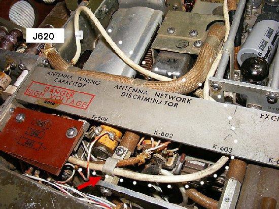
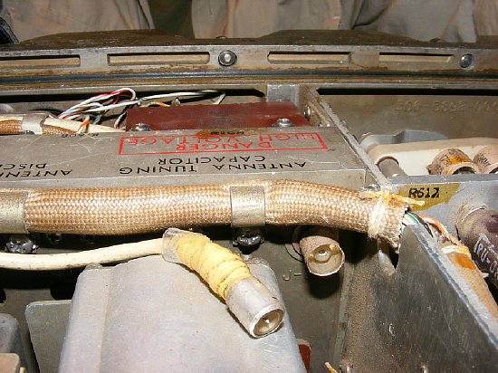
The FSK IN cable (white dots) connects to the front panel BNC and is buried in the front of the chassis and emerges with a long lead from under the phenolic cover for CR602,C642. In the example above the FSK IN cable is connected to J620 on the main transmitter chassis. J620 is connected to the MO front BNC connector on the front of the chassis.
This is a closed circuit and the cables are in the "stowed" or Non FSK configuration. The MD-203 will not be functional with this cable configuration.
 When
the interior cables are "stowed" there will be continuity or
a direct short between the two BNC connectors on the front of the transmitter.
Use your ohm meter.
When
the interior cables are "stowed" there will be continuity or
a direct short between the two BNC connectors on the front of the transmitter.
Use your ohm meter.
Configure cables for the MD-203 by plugging P601 into J101. Plug P801 into J602.
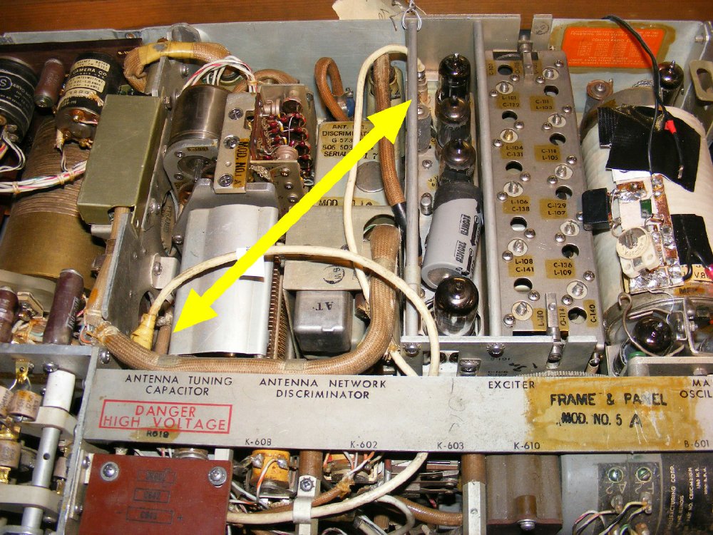
In this photo to configure the front FSK IN and MO (BNC) connectors for the MD-203. Just switch the male end connection for the cables. Carefully unplug the top cable from J101 on the multiplier chassis and the bottom cable from J620 and swap.
 Q. Can I still use the
T-195 on AM and CW with the cables configured for FSK?
Q. Can I still use the
T-195 on AM and CW with the cables configured for FSK?
A.
Yes but the MD-203 needs to be powered and ON and the correct band selected.
Q.
Can I still use the T-195 on AM and CW with the cables confirgued for
FSK?
A.
Yes you can just disconnect the MD-203 cables and run a short BNC jumper
between FSK IN and MO on the T-195
Q.
Can I use the FSK IN on the transmitter for an external VFO?
A.
Yes as an experiment try driving with 3 to 5 volts PP.
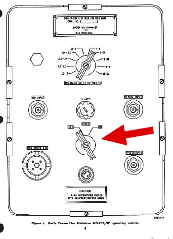
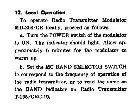
![]() Power switch must be ON and the correct Band
selected for "Local" operation. Selection of the wrong band
on the MD-203 will result in low drive for the multiplier stage.
Power switch must be ON and the correct Band
selected for "Local" operation. Selection of the wrong band
on the MD-203 will result in low drive for the multiplier stage.
Local operations can also be accomplished by disconnecting MO
and FSK cables between the transmitter and the MD-203 and
substituting a short BNC jumper.
TM
11-5820-205-10 Chapter 2.
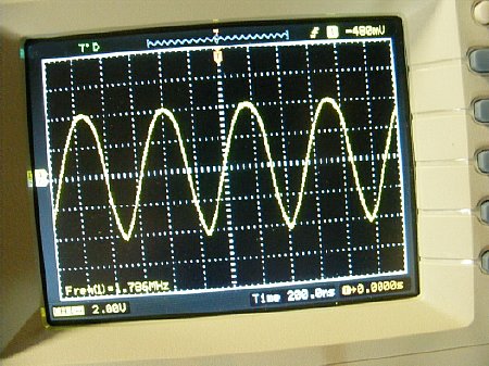 Measursement made on the Master Oscillator while feeding
the front MO connector (BNC) the voltage should be approximately
8 volt PP measured at the connector.
Measursement made on the Master Oscillator while feeding
the front MO connector (BNC) the voltage should be approximately
8 volt PP measured at the connector.