Part 5 contains information on a solid state Vibrator replacement board. Filament voltage and bias voltage adjustment. More Ballast Info. Alternate filament voltage supplies.

I've jumped around quite a bit with these pages with a lot of emphasis on the correct filament voltage. Be sure and read Part 4 and combine that information with Part 5 before making any decision on making changes to the 1.5 volt filament voltage circuits.
Please test your choice of circuit(s) before making a permanent installation. There are many factors that effect the 1.5 volt filament supply.
![]() The 1.5 volt filament supply is critical. Voltages must
be within specified parameters otherwise the receiver may not function
properly especially when operated under varying battery supply conditions
when portable or from a vehicle. In the event excess filament voltage
is applied to the 1.4 volt tubes - the tubes may be damage. .
The 1.5 volt filament supply is critical. Voltages must
be within specified parameters otherwise the receiver may not function
properly especially when operated under varying battery supply conditions
when portable or from a vehicle. In the event excess filament voltage
is applied to the 1.4 volt tubes - the tubes may be damage. .
BE
sure and identify which serial number series you have and use the correct
schematic. See "Identify Version" in Part 4.INDEX Click to Navigate
Suggested
Test Fixtures
Aurora
Design VBX-1 Vibrator Board
Low
voltage rectifier replacement.
More
Ballast Info
Low Filament
Voltage
Using
a LM337 Regulator
Bias Voltage
Discussion
 High Voltage
Bleeder resistors are not installed on the PE-104 for the High voltage B plus and Bias supplies or any of the low voltage circuits. Discharge capacitors on the PE-104 before working on the set. Examine the schematic. Remember that the ground on some of the capacitors is "Radio Ground" and on others the ground is "Chassis" ground.
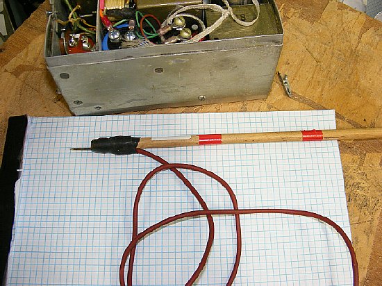
A simple shorting stick suitable for receiver power supplies. When dealing with transmitter power supplies a more sophisticated stick will be needed with better insulation. In any case route the ground wire away from your body.
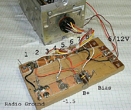
As discussed in Part 4 a break out test board comes in handy.
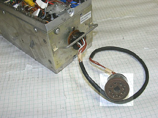
And as we discussed in Part 4 an extension cable comes in handy.
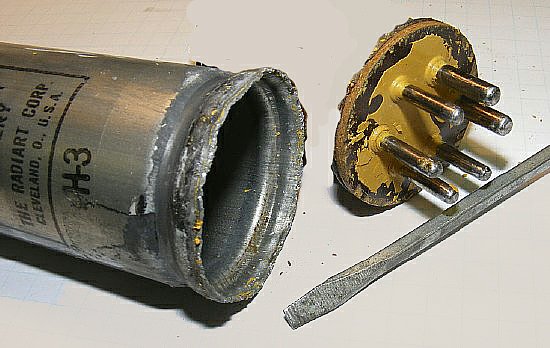
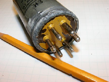
The
PE-104 uses a standard 8 pin octal plug.
When wiring the plug for the PE-104 extension cable add extra bare wire tabs in order to measure voltages.
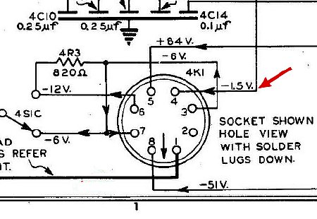
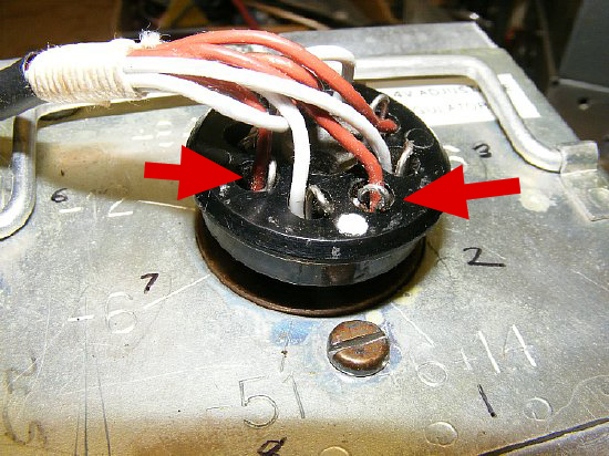
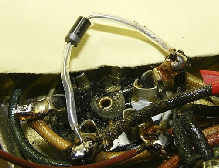
![]() Be
careful when measuring voltages on the PE-104 4K1 socket. Pin 4 is the
-1.5 volt filament output and it is located
right next to pin 5 the +84 volt output
and next to pin 3 the 6 volt output if used. A slip of the meter probe
could result in blown filaments.
Be
careful when measuring voltages on the PE-104 4K1 socket. Pin 4 is the
-1.5 volt filament output and it is located
right next to pin 5 the +84 volt output
and next to pin 3 the 6 volt output if used. A slip of the meter probe
could result in blown filaments.
CLICK
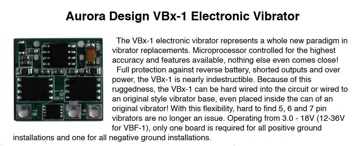
to enlarge. Shown here is a portion of the Aurora PDF file - see link
below.
Aurora makes a small microprocessor based board to replace the mechanical vibrator. Aurora is the only company that I am aware of that has a vibrator replacement board that will function in a "Positive Ground" circuit. An interesting specification is that the board will operate from 3.0 to 18 volts. Another version is designed to operated from 12 to 36 volts.
A PDF file with specifications is available from the Aurora Site.
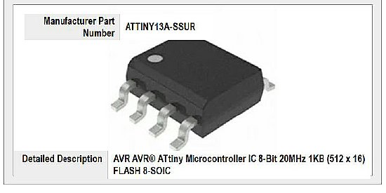
The Aurora vibrator replacement board uses a 8-bit Microcontroller.
 RFI? Input Voltages?
Q. When utilizing the vibrator substitute board made by Aurora are any spurious emissions "Birdies" found on 75 or 80 meters.
A. No, the board when installed inside the vibrator can or hard wired to the bottom of the vibrator socket was very quite across the entire band.
Q. The specifications state that the board will operate down to 3.0 volts input. Did you test this?
A. Yes but at 3.0 volts the input to the PE-104 will be too low to produce any useable voltages. But the board is perfect for other low voltage applications. Another version of the board is designed for 12 to 36 volts.
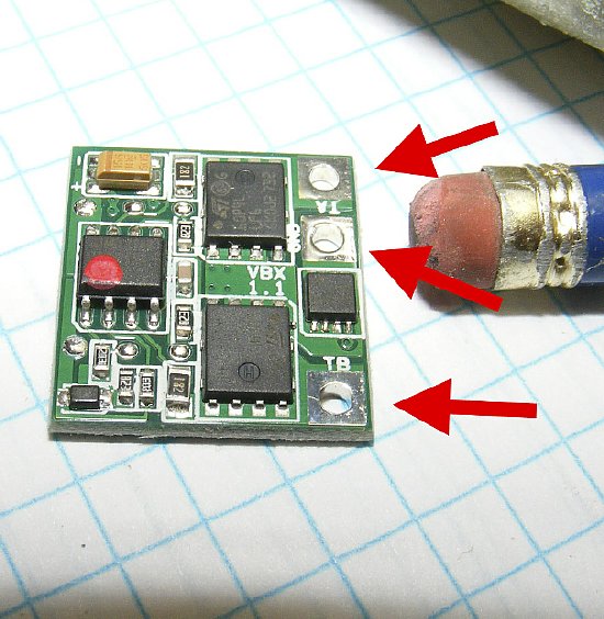
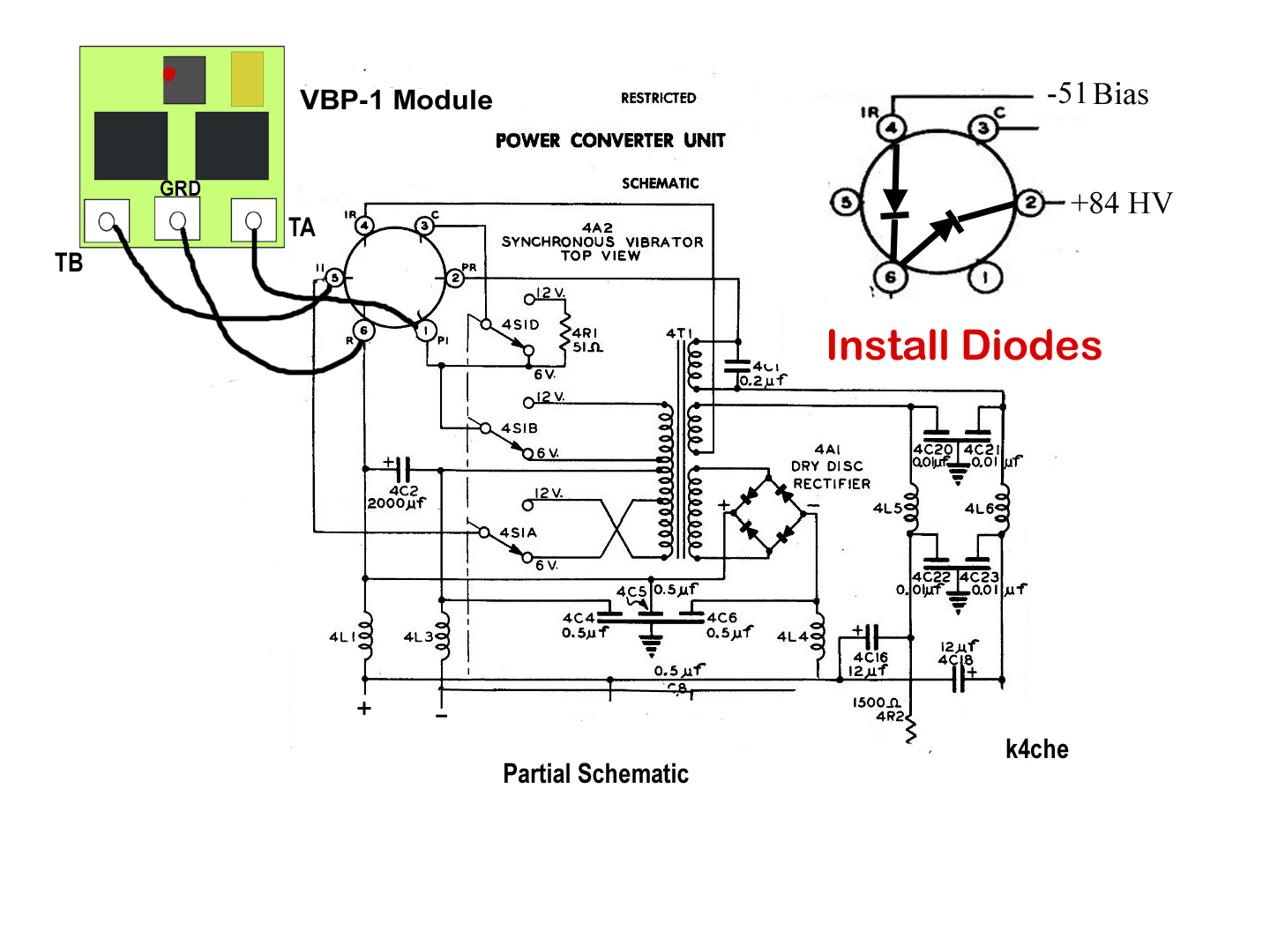
The board is installed using 3 connections TA, TB and GRD. TA and TB are interchangeable connections and connected to the transformer primary winding. Available in two versions Positive and Negative ground. The PE-104 uses a "Positive" ground system.
CLICK
to enlarge
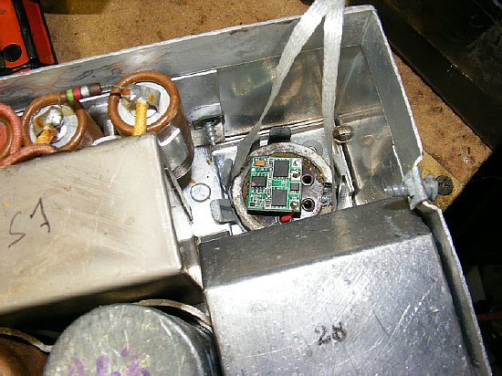
The VBP module can be hard wired under the chassis to the vibrator socket or use the vibrator base and retain the plug in feature.
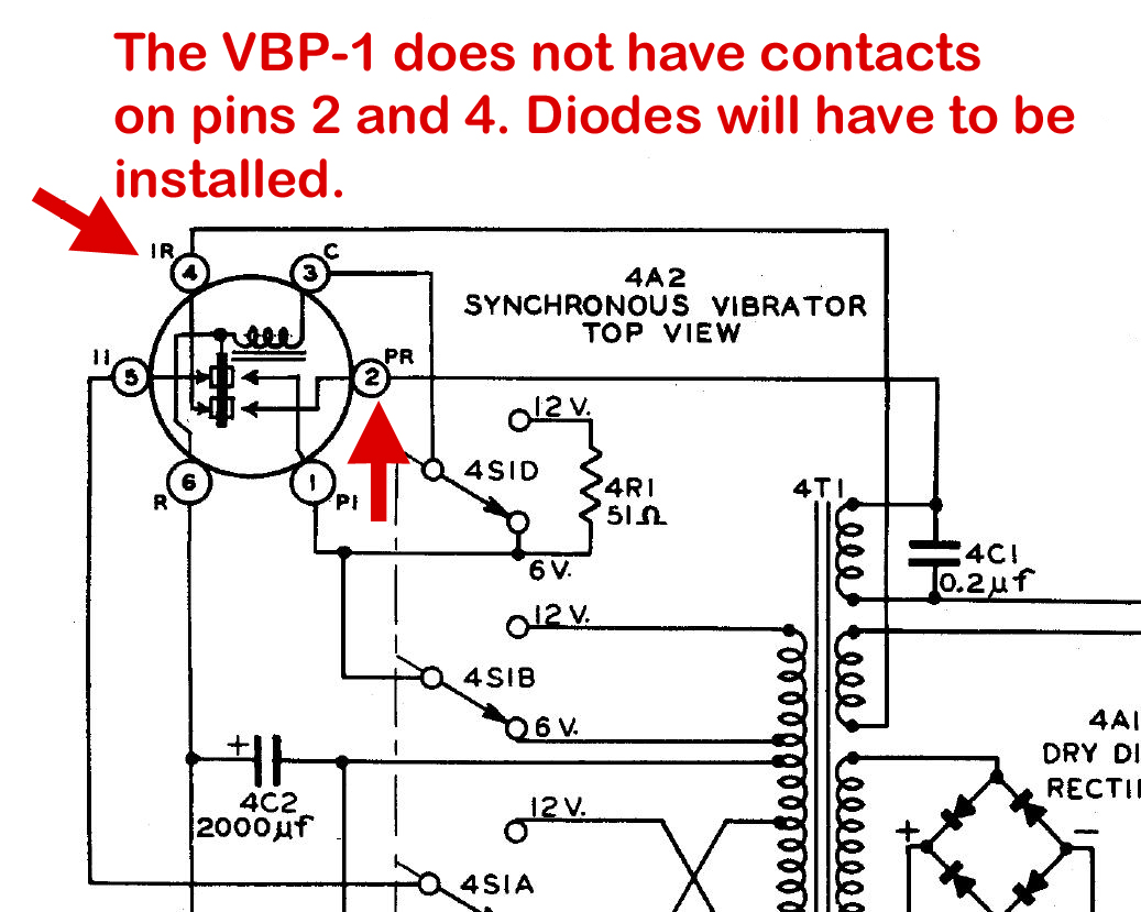
The
VBP-1 module does not provide rectification of High Voltage and Bias as
it only provides excitation of the transformer primary. A DIODE
for the High Voltage and Bias Voltage must be added by wiring both diodes
inside the vibrator can or soldering the diodes to pins on the vibrator
socket under the chassis. .
CLICK to enlarge
The VBP-1 is wired to the primary of the transformer only. Diodes have to be connected with the proper polarity between radio ground pin 6 and the high voltage winding pin 2 and bias winding pin 4.
There is plenty of room inside the vibrator housing.
Diodes
Q. Why do I need to install diodes when using the
VBP-1 board.
A. The VBP-1 board does not provide rectification of the 85 volt
B plus and the -51 volt Bias
Q. Why use only one diode for HV and one for Bias?
A. One diode is all that is needed for a "half wave"
circuit.
Q.
Where can I install the diodes?
A.
You can install the diodes inside the vibrator can or on the vibrator
socket chassis.
Q. Why install the diodes inside the vibrator can?
A. Installing inside the can allows the vibrator can to be a complete unit and then it can then be used on different power supplies.
Q. Why not just install the diodes under the chassis on the vibrator socket pins?
A. You can. Installing the diodes on the vibrator socket pins allows easy replacement in event you short out the power supply and blow a diode. Installing the diodes inside the vibrator can is neat but in the event you blow a diode you have to open the can back up. Just choose one and get on with the project. Flip a coin if necessary.
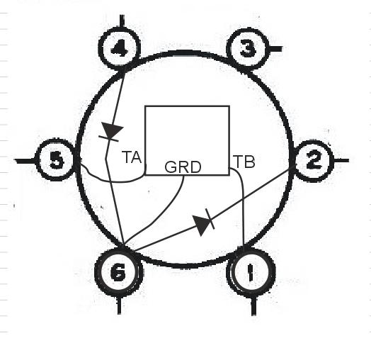
VBP and diodes wiring top of socket view. Pins are underneath. Pins 1 and 6 are larger pins. Pin 6 is the Positive return for the circuit. TA and TB connections are interchangeable.
Connections TA and TB on the VBP-1 board are interchangeable and can be
reversed
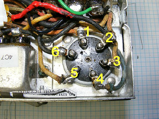
Bottom socket view. Note the large pins 1 and 6. Pin #2 is easy to identify as it connects to the buffer capacitor 4C1. The buffer wire was painted Red when I was working on the unit.
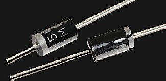
Diodes? Any general purpose power supply diode can be used. 1N4007
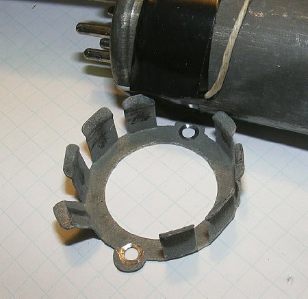
The hold down assembly for the vibrator is a PITA. I removed them.
Attach
a lanyard to the bottom of the vibrator plug to help with extraction after
it is plugged in.
The diodes can be soldered to the socket pins underneath the chassis in lieu of installing on the vibrator can base. Shown above a diode tack temporarily installed for testing of the B plus.
Voltage increase
Q. Will the voltages from the power supply be higher with the use of silicon rectifiers?
A. Yes. In the case of the B+ and Bias the voltages will be slightly higher. Since the Bias voltage will effect transmitter power output a adjustment procedure will be discussed later on this page. The small increase in B+ will not be noticed in receiver or transmitter operation.
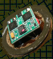
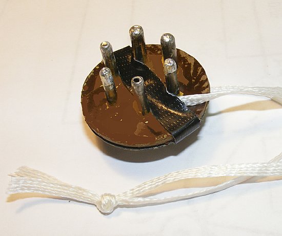
Vibrator
base with the board installed. Diodes were installed under the VBP-1 board
and are hidden by the board. During testing of the board the lanyard
helps with extraction of the vibrator base out of the socket.
Reassemble the vibrator can. DO NOT glue with Epoxy etc. you may have to reopen the can later. Don't be in a hurry and carefully bend the metal back into place.
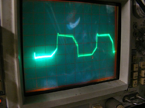
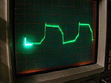
Scope photo of the VBP-1 vibrator board wave form. Bench frequency check in this case was a steady 116 cycles under varying load and voltage conditions.
Video of the bench frequency check:
Component labels help in testing and trouble shooting.
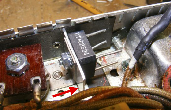
Low voltage Rectifier Replacement (4A1)
CLICK to enlarge. Early version schematic. See Section
4 on how to Identify which version of the PE-104 you have.
Most of the PE-104's have a shorted "Dry Disk Rectifier" 4A1. The rectifier provides DC voltage to the 1.5 volt filament buss.
The above schematic does not have the Ballast Rectifier for the 1.5 volt
filament buss. The Ballast was installed on later models of the power
supply. Please read Section 4 and there is more Ballast info on this page.
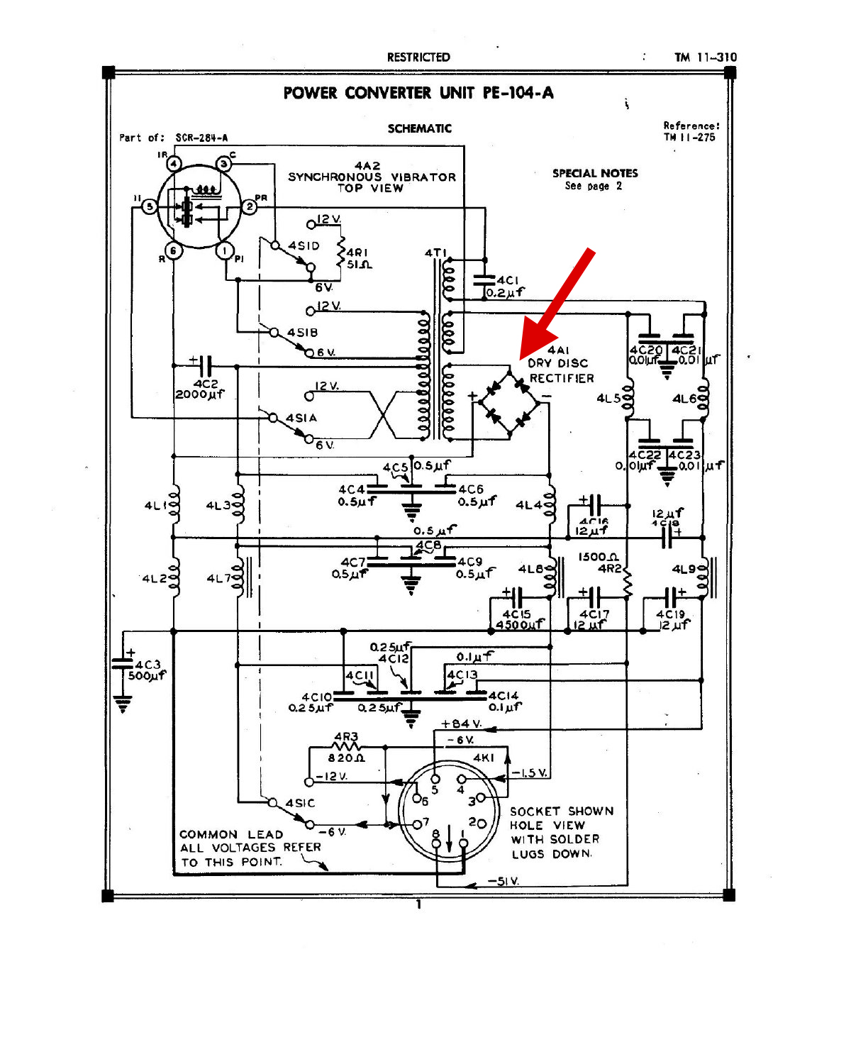
The
1.5 volt dry disk rectifier is mounted on a metal bracket at a 90 degree
angle to the chassis. The Ballast Rectifier is mounted on similar bracket
at the bottom. (Left)
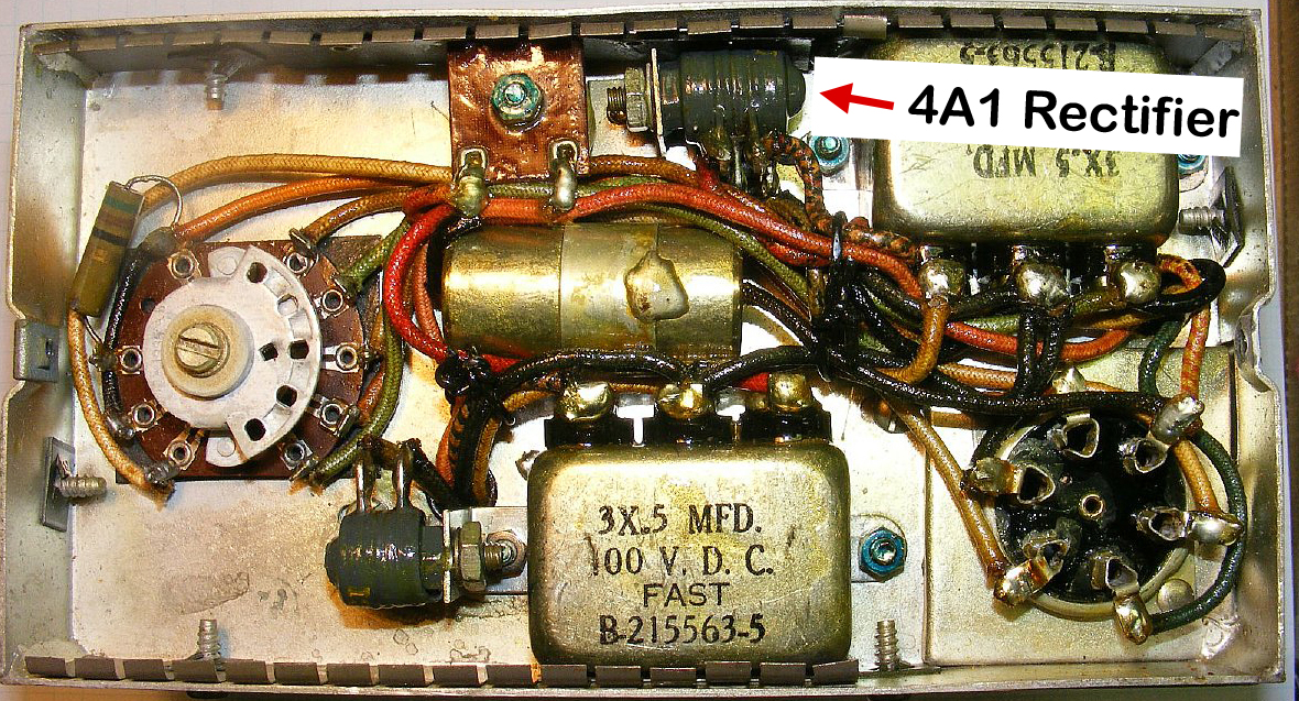
There are numerous small bridge rectifiers made in a "brick" configuration. A DB604 is shown above and is mounted on the original chassis bracket. Note that on the power supply chassis shown above I added an additional heat sink area with a piece of aluminum. On further power supplies this step was omitted and is probably overkill for heat dissipation. The filament supply draws 400 mA and the AC input to the bridge is approximately 3 volts.
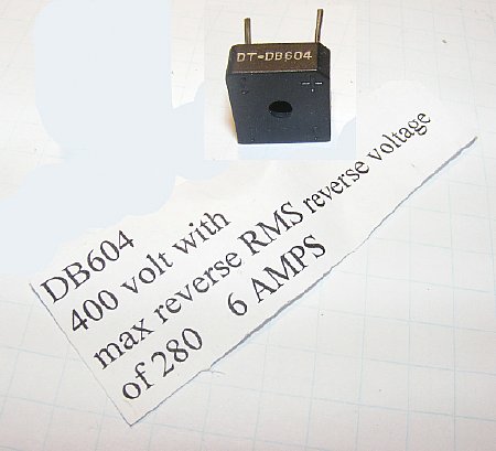
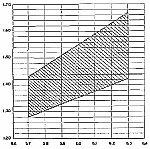
The DB604 will easily handle the low voltage and current required to supply the 1.5 volt filament buss. The filament supply requires 1.5 volts at .4A (400 mA) amps. The receiver will tolerate voltages variances within specified limits - see chart below. See Part 4 on testing etc.
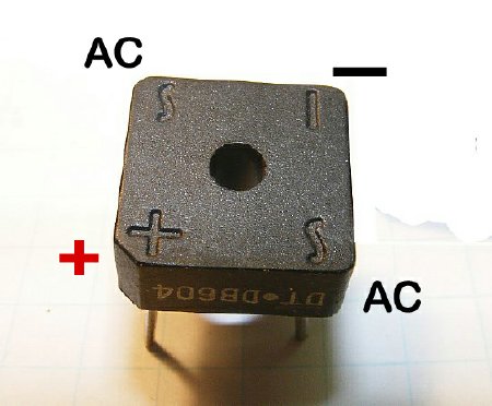
Most Diode Bridge modules are clearly marked.
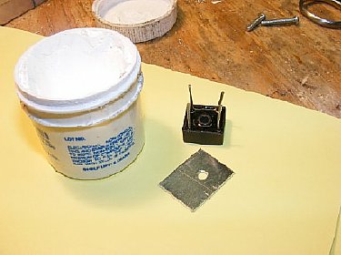
Don't forget to use heat sink compound or paste.
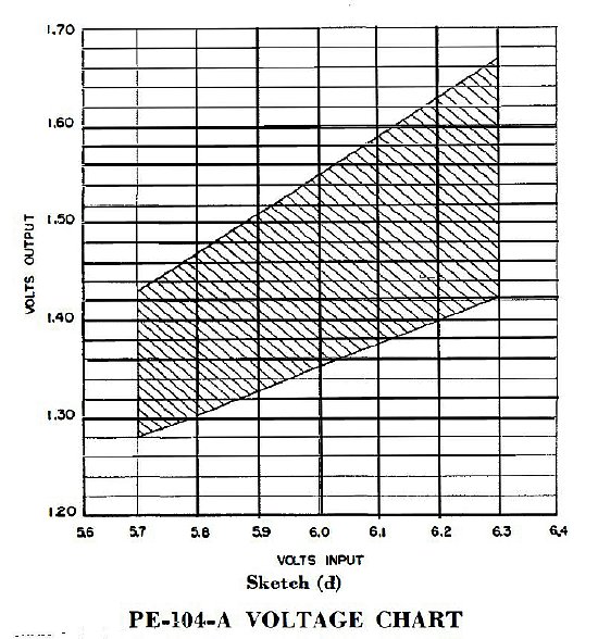
The 1.5 volt filament circuit requires a nominal voltage as shown in the shaded area above. The filament voltage output from the transformer bridge circuit varies with the 6 or 12 volt input to the vibrator circuit on the primary side. Be sure and read Paragraph 35 and examine Sketch (d) in the manual.
Test your PE-104 power supply over a wide range of input
voltages such as11.0 to 14.0 to ensure proper filament voltage. When operating
the power supply from a vehicle battery while being charged by the generator
expect 14 volts or higher input to the vibrator circuit depending on what
voltage the regulator is set on. Same procedure applies when using a 6
volt system.
![]()
When the filament voltage is too low the receiver sensitivity and audio output are reduced. When the filament voltage is too high the tube life is reduced. Exposing the tube filaments to a higher voltage for even a short period and then reducing it to its required value is not good for the tubes and may result in reduced tube gain and life.
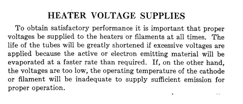
N3FRQ comments: "Battery tubes use a chemical coating on their tungsten filaments. This allows them to emit sufficient electrons at modest temperatures, (700 F) and low power. In an over-voltage condition, the filament can go to a much higher temperature without melting, but the coating may evaporate, resulting in reduced emission. Here's a blurb from the 1935 Sylvania Tube Manual:
CLICK
to enlarge
More Ballast Rectifier Information
Read the information on the Ballast Rectifier in Section 4 of the manual. Later versions of the PE-104 had a Ballast Rectifier added to the -1.5 (minus 1.5) volt filament circuit to aid regulation and prevent over voltage.

CLICK
to enlarge. Late model schematic.
Later models of the PE-104 had a Ballast Rectifier.

After
bench testing the Diode brick as suggested by WA5CAB it can be mounted
on the original Ballast bracket or you can fabricate a bracket. When using
the original bracket I recommend using an additional aluminum plate for
a heat sink.
![]() Try
the diode brick as suggested above but you may find that the 1.5 volt
buss voltage is too low. Different diodes have different voltage drop
characteristics.
Try
the diode brick as suggested above but you may find that the 1.5 volt
buss voltage is too low. Different diodes have different voltage drop
characteristics.
Q. I replaced the 4A1 bridge which was shorted and then measured my filament voltage under a resistive load (3.5 ohm = 400 mA) the 1.5 volt filament buss was low around 1.3 volts. I realize that with a fresh 12 volt battery the voltage may be higher but I would like to raise the filament voltage slightly as I plan on operating in portable in the field at a military rally using a battery which would slowly discharge down to less than 11 volts during extended operations. I don't want to lose receive capability due to low filament voltage.
A. You can try using a Schottky low loss bridge in place of the normal bridge 4A1. The Schottky diodes in the bridge will have less voltage drop resulting in slightly higher voltage output. Remember that we are dealing with tenths of a volt. On one power supply I used a D30XBN20-7000 Schottky diode bridge.(Mouser part # 627-D30XBN20-7000) but had to find a alternate mounting place for it.
Q. Why not just use a LM-337 "Negative Voltage" adjustable regulator and set it to 1.5 volts.
A. You can and it provides a worry free filament voltage. Be sure and order a "Negative Regulator."Info later on this page. .
Q. I am not worried about the filament voltage so I will just replace the 4A1 bridge and see what happens.
A. Good luck.
Q. Why not just hang a D cell battery pack to provide the 1.5 volts for the filament Buss.
A. That will work and will be ugly but will get the set operational with a reliable voltage source for the 1.5 volt filaments. SEE BELOW. Sometimes it pays to use a Ugly solution and at least get the radio in operation and off of the shelf. There are a lot of BC-654 sets that are just sitting around and have never been used.
.JPG)
On one power supply I had low filament voltage and installed a Schottky Bridge for the 1.5 volt filament buss. The bridge was rather large so I mounted it on the side of the chassis on a bracket. No other circuits were added just this bridge. In this case the filament voltage met specifications.
BE PREPARED to test various filament circuits in order to arrive at proper filament voltage to meet your operational requirements.
Another Filament Voltage Solution. (D Cells) Ugly but easy.
Battery
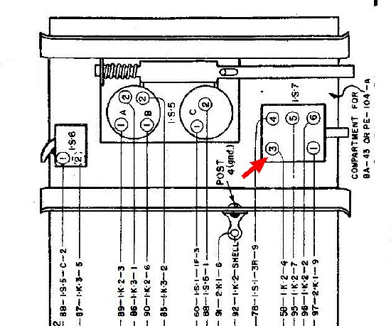
Compartment Switch Wiring. Emergency D cell pack
voltage Point.
Switch 1S7 interrupts the 1.5 volt filament buss when depressed. Terminal 3 goes to the main power connector. Disconnect the wire to terminal 3 and hang your D\ cell pack Minus on terminal 3 and use 1S6 for your "Radio Ground and connect the D cell pack Positive.
The Battery Compartment Switch panel was discussed in detail in "Part Two".
![]() Switch
1S7 shown above is wired differently on earlier sets with serial #1 to
3500. Check your individual schematics. Remember that the "Ugly"
1.5 volt D cell pack will be wired with the positive to "Radio Ground"
and the negative to 1S7.
Switch
1S7 shown above is wired differently on earlier sets with serial #1 to
3500. Check your individual schematics. Remember that the "Ugly"
1.5 volt D cell pack will be wired with the positive to "Radio Ground"
and the negative to 1S7.
![]()
On one power supply I replaced the bridge rectifier but the output from the PE-104 filament circuit was too low even with a Schottky bridge. All components were checked for leakage and the Ballast had never been installed so that was not the problem. There just was not enough output from the low voltage winding on the transformer to produce enough voltage for the Bridge Rectifier. A LM337 voltage regulator circuit was installed. A drastic solution but in the end provided a well regulated filament voltage to the sensitive 1.4 volt tubes. In addition to providing a well regulated filament voltage the LM337 has internal "Short - circuit current limiting protection." And other features.
1.5
Volt Filament Supply.
Using a LM337 Negative Voltage Regulator

CLICK
to enlarge
By utilizing
a LM337 "Negative Voltage Regulator" a reliable 1.5 volt source
can be achieved. Impervious to the input voltage. Note the polarity of
the capacitors with Positive going to circuit ground.
R2
is a adjustable pot 250 ohms or less. R1 can be 220 or 240 ohms.
Here is a site
with a adjustable calculator for the R values and includes a simple table
of standard resistor values if needed.
http://www.reuk.co.uk/wordpress/electric-circuit/lm317-voltage-calculator/
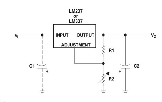
Note: that the capacitor(s) Positive + side goes to circuit ground which in this case will go to "Radio Ground" not the chassis.
A small circuit board with the LM337 can be inserted into the top of the PE-104 chassis near the voltage switch. The 1.5 volt Bridge and Ballast (if installed) are no longer needed and should be disconnected.
The parts for the LM337 circuit can be mounted on a piece of perf board or a copper clad board with groves cut in it to separate the solder "Islands". Use a Dremel tool or a Xacto knife. The fixed resistor is 220 ohm and a small 250 ohm variable was used. The variable is not critical but should be in the low 100 ohm range. The 1 uF caps are fairly large but were found in my capacitor box so they were pressed into service. Smaller capacitors could be used such as tantalums and the entire board could be smaller.
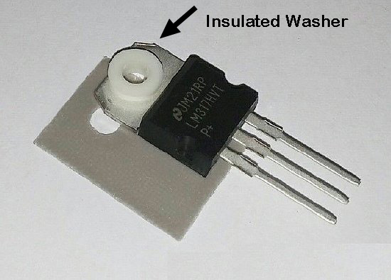
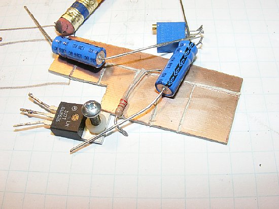
The LM337 in a TO220 case is mounted to the chassis and uses the chassis for a heat sink. The regulator needs to be insulated from the chassis. The regulator is rated at 1.5 Amps. The BC-654 filament circuits require .4A or 400 mA.
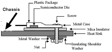
Insulate the LM337 from the chassis. The chassis is the heat sink.
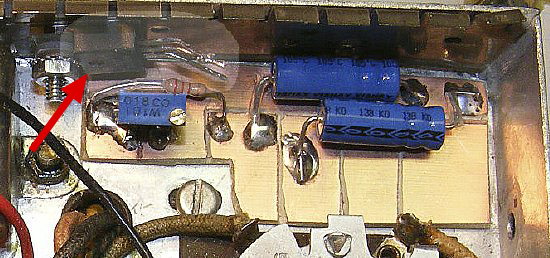
Connect the LM337 which is mounted to the side of the chassis to the copper clad board circuit with short leads. See next photo.

LM337
Regulator Connections
Plenty of room on the board for components and connections. Remember that the Positive + on the caps go to GRD.
CLICK
to enlarge Early model schematic
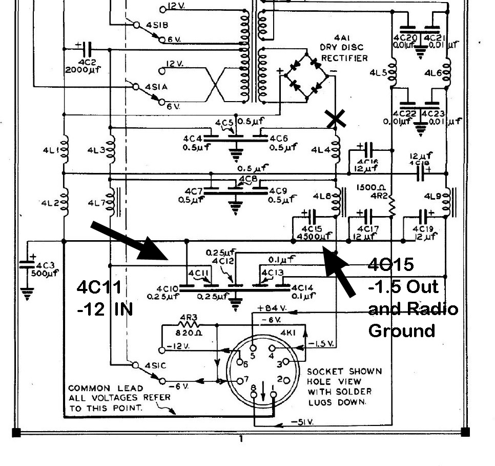
4C11 is a good source of -12 volts for regulator input. The terminals on 4C15 can be used for Regulator -1.5 Out and Radio Ground. Disconnect bridge wiring. The 4L4 choke was only used on early units . . .
![]() Do not use capacitor 4C6 and choke 4L8 in your circuit, 4L8 will interfere
with voltage regulation. Connect the output of your regulator to 4C15.
Do not use capacitor 4C6 and choke 4L8 in your circuit, 4L8 will interfere
with voltage regulation. Connect the output of your regulator to 4C15.
Identify
which serial number version you have, the schematic shown above is for
Early Units serial #12,000 and below. However 4C15 and
4C11 are present on all versions of the PE-104.
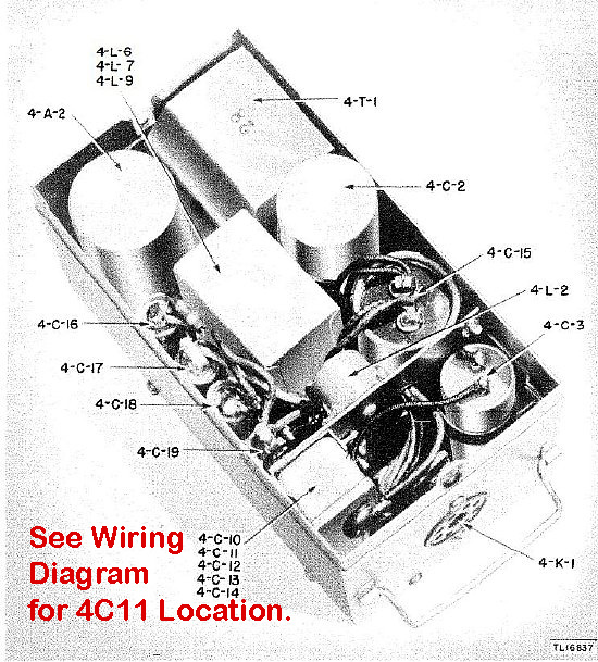
The
pictorial of parts location sometimes is misleading. The capacitors in
the stack at the bottom left are not in order. In this case capacitor
4C11 is actually at the top of the stack.
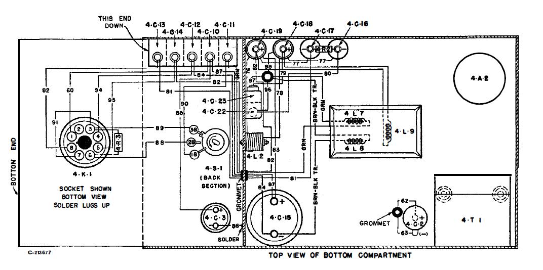
4C11 is located at the top of the capacitor stack. 4C10 is second down from the top.
An optional 10 ohm resistor was inserted on the -12 volt input line to the regulator to reduce voltage input to the LM337 and reduce heating of the IC.
Adjusting Bias Voltage on the PE-104
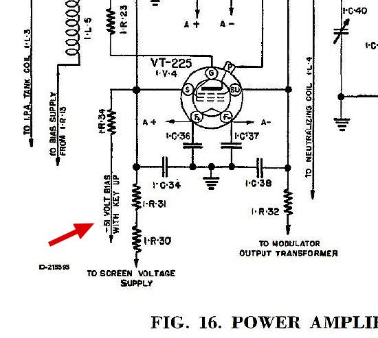
The bias voltage is used in several stages of the receiver and transmitter. One of the stages the final amplifier is shown here with -51 (minus fifty one volts) available under KEY UP no load conditions.-
CLICK
to enlarge
The
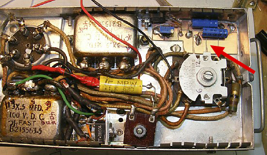
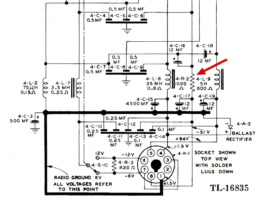
bias voltage can be adjusted by changing the value of 4R2.
CLICK
to enlarge
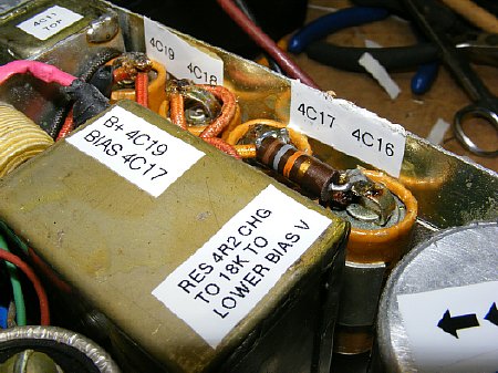
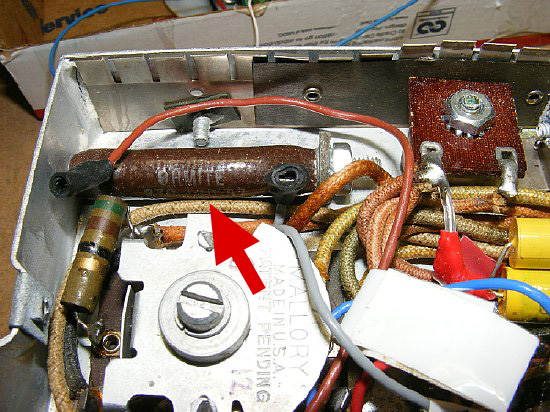
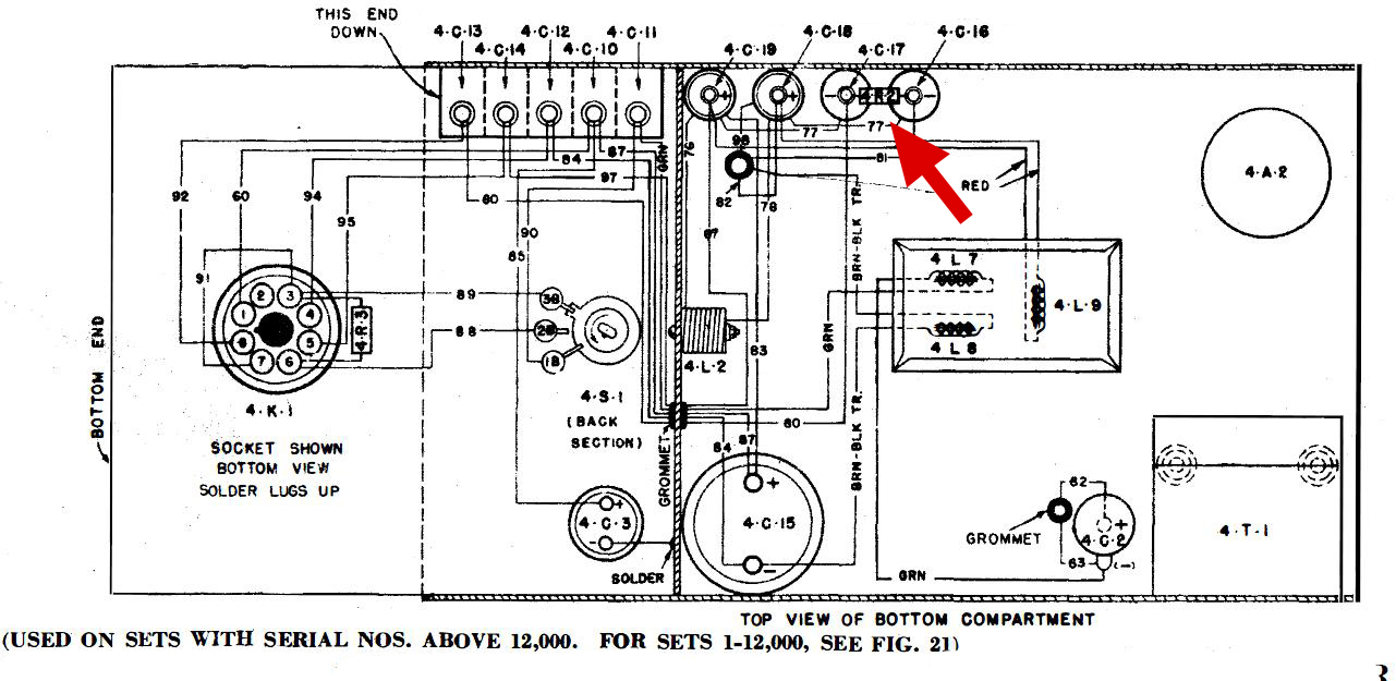
Its
easy to locate 4R2 as it is soldered to the top of capacitors 4C16 and
4C17.
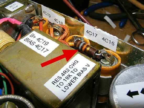
My
bias voltage when measured on one supply was all most 80 volts so I changed
the resistor.
When measuring your bias use the top of 4C17 as a test point.
 BIAS
BIAS
Q. How much current does the transmitter and receiver bias circuit consume?
A. Not very much approximately .5 mA (point five milliamps). Leaky capacitors may result in a slightly higher value.
Q. How can I test the bias voltage while working on the PE-104 without the radio ?
A. Load the bias circuit down with a test resistor of 100K ohms. (One hundred Thousand).
Q. The bias voltage listed on the transmitter schematic is -51(minus 51
volts) for the PE-104 but for the BA-41 battery the voltage is -45 (minus
45 volts).
A. Either voltage may be used. See next question.
Q. Will transmitter output be effected by the bias voltage.
A. Yes. A low bias voltage will result in increased RF output and modulation will decrease. During bench testing reducing the bias to approx -35 volts resulted in a increase in RF output of a couple of watts with the transmitter operating AM in the High power position. Over voltage above 70-80 volts will decrease RF output by several watts.
Q. My radio works fine so I am not going to measure or test the bias supply.
A. Okie Dokie