Use
OTS boards to simulate an RY signal for local loop or TU keying.
 Two
versions using 555 boards are presented here. One for local DC loop keying
and the other for keying a "Mark Only" tone for TU input. A Two
Tone board will be presented later.
 An OTS Chink 555 board (on ePay)
drives an optocoupler which can key the local loop. More info below.
The large outboard
Pot mounted on the metal bracket replaced the original board mounted wide
range miniature pot. The large pot provided easier control/resolution
of the pulses at slower speeds.
 When
you replace your miniature frequency pot check its resistance. Some boards
used 10K and others used 100 ohm.
The unit is power by a 9V battery and
the battery connector serves as a switch. KISS.
The
local loop is connected via the 1/4 inch jack.
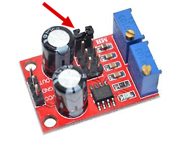
When
searching for 555 boards on ePay - be sure and purchase boards that have
two (2) pots. One pot is for frequency and the other is for pulse width.
These boards usually have an "Output" LED triggered by the output
pulses.
A jumper on
the board above selects different capacitors for four (4) frequency ranges.

Q.
Why purchase a 555 Chink board on ePay when you can build a 555 circuit
in 30 minutes?
A.
Its hard to get hams to build anything anymore but go for it. ePay boards
are cheep and have a built in wide frequency selection, an output
LED, adjustable pots as well as a lot of features.
Q.
Why not just use a 555 pulse generator without all the adjustments?
A.
You need to be able to adjust speed and pulse width in order to create
a proper square wave.
Q.
When adjusting the speed of the circuit - won't that effect the pulse
width?
A.
Yes, its a simple circuit so be prepared to adjust back and forth.
Q.
Can I use the RY generator to adjust the "Range" on my model
15?
A.
You can use it for initial testing but you should actually use another
machine source for fine tuning the range.
Q.
What about carriage return and line feed?
A.
Its a simple RY generator.
Q.
Why do I need this RY generator when I can just type R and Y on the keyboard?
A.
Allows you to have hands free to make machine adjustments while printing
RY's.
Q.
Those little tiny pots on the Chink boards are hard to adjust.
A.
I replaced the frequency pot with a larger 1/2 watt.
Q.Why
does my 555 board output LED stay on continuously?
A.
You have to select a slower speed to observe the pulses.
Q.
Everything is exposed on your wooden board - - is this dangerous?
A.
Don't touch the DC loop jack wiring when plugged into a loop that is not
terminated.
Q.
Why not just use computer software and record RY's and play them back
thru the TU?
A.
Yes but the RY generator is a very compact board and easy to use.
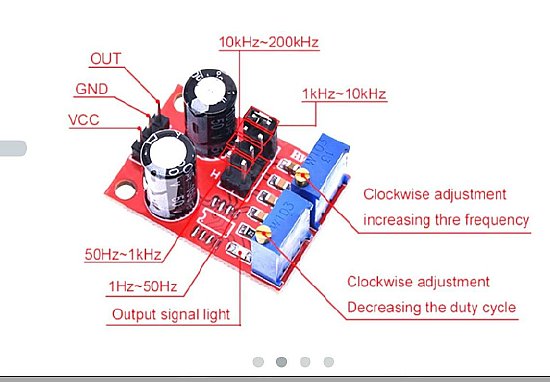
Typical
Chink board with "Two Pots". Cheep. Buy 3 or 4. Help the Chink
economy.
Note that the board has a Pulse or Output Signal Light (LED).
 The LED will appear to remain on continuously at the higher speeds/frequency.
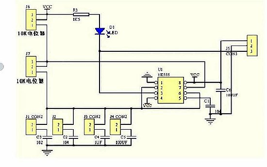
Typical ePay board schematic. Your board may be different.
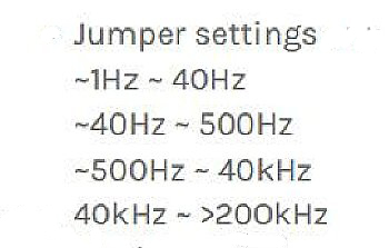
Typical speed/frequency settings.
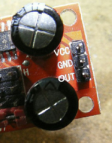
Typical "Header" connector for a ePay 555 board. Pins have a 2.54(two point five four) mm spacing or .1 inch.
Do a search on ePay for "Header Connector" and you can buy a complete connector kit.
555
Pulse Board from a Kit Board and was marked HW619.
555
Board built from a kit. Note the IC socket and the large LED. The small
frequency pot was removed and replaced with an external 10K pot with a
22K resistor in series for the 22 cps range.
 The LED resistor in the kit
was 1500 ohm and the LED was too dim, I used 470 ohm.
 The
Dovetron TU series have a built in RY generator. - - I copied their
frequency scheme.
The
goal is to generate a square wave at approx. 22 (twenty two) cycles per
second with a "50 percent" duty cycle.
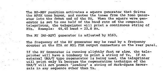
CLICK to enlarge
The Dovetron Terminal Units have a built in RY generator.
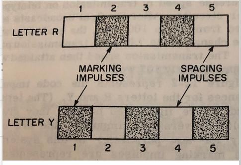
A Square wave created by the 555 board emulates the RY pattern.
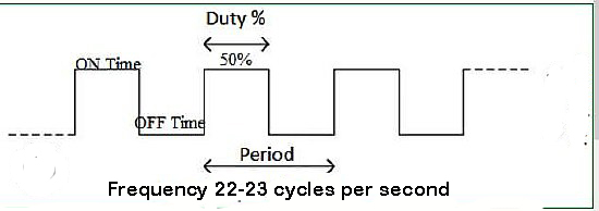
Diagram source unknown.
The object is to have a symmetrical square wave with a 50% duty cycle - frequency 22-23 cycles.
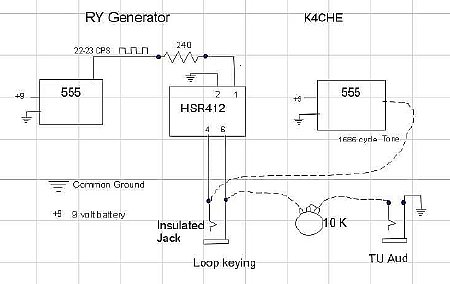
Click to enlarge
The
small copper clad boards used as distribution boards were made with a
Dremel tool.
Basic
RY loop test board. The 555 board sends pulses ![]() which key an Optical keyer (HSR412) which in this example the output is
connected to the 1/4
inch phone jack for local loop DC keying.
which key an Optical keyer (HSR412) which in this example the output is
connected to the 1/4
inch phone jack for local loop DC keying.
 You will need a 240 ohm current limiting resistor between
the 555 board output and the HSR412.
Click
to enlarge
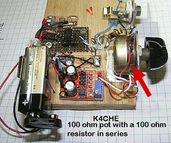
An external
pot replaced the on board miniature pot for easier frequency control.
On this particular 555 board (marked YL107)
I used a 100 ohm pot with an additional 100 ohm resistor in series.
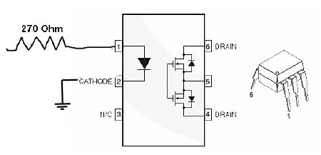
HSR412
Use a current limiting resistor on the input of the HSR412.
 Pin
6 and 4 will be utilized to key the DC loop.
Back
to back mosfets are used for keying - - HSR output pin connections to
the loop jack are not polarity sensitive.
Typical Voltage and Current Measurements. (Fresh 9 Volt battery used for power)
 555
Board pulse output with HSR load was 7.5 volts measured with a Simson
260 Analog meter.
The same pulse without the HSR load was 8.5 volts.
Current on the "output" line with the HSR412 load was 15 to
20 mA.
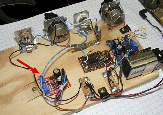
An
additional 555 "Tone" board added for Mark Only.
Later I mounted an additional
555 board which generated a steady audio tone of 1575 cycles. The steady
tone output is used for Mark Only keying and the audio is keyed by the
HSR412 board. A 20K pot is used for output level control.
Video Mark Only.
 A
two tone(Mark and Space) board using a XR2206 chip. FYI: Dovetron uses the
same IC.
