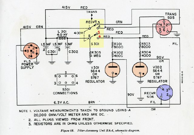
NOTE: The toggle switch S-301 on the filter Accessory Unit controls the B + for receive and and transmit. During transmit the RS-6 receiver is inoperative.
B Plus Path with S301 TOGGLE SWITCH ON TRANS:
The 415 Volt source from the power supply enters the filter unit at connector PL3 pin 3 and then is connected to terminal 1 of the toggle switch-- In Transmit this switches the HV is switched to to terminal 3 of the switch.
Terminal 3 then goes to the TRANS socket SO5 terminal pin 2. PIN 2 is inner connected inside the transmitter to transmitter PL 5 Pin 6. Pin 6 then supplies B+ back to the Filter Accessory Unit TRANS socket SO5 pin 6 which then feeds terminal 4 of the toggle switch. (Wonder what rocket scientist did this?)
Terminal 4 of the toggle switch then feeds the B + through choke L301 and then goes to terminal 2 of the toggle switch.
In transmit TRANS mode terminal 2 of the toggle switch feeds terminal 5 of the switch which then goes to pin 3 of the TRANS power socket which then finally feeds the B+ circuit for the transmitter. (Your government tax dollars at work.)
The RS-6 radio system depends on the interconnect present in the transmitter between pins 2 and 6. Since the B+ is removed from the receiver you can not zero beat or hear any signal.
B Plus Path with S301 TOGGLE SWITCH ON RECVR:
The 415 volt line goes to terminal 1 of the toggle switch and connects to terminal 4 of the toggle switch which feeds the TRANS SO5 pin 6 which is again inter connected to pin 2 which then returns to the toggle switch terminal 3 which due to the position of the switch is now open.(Wow)
Terminal 4 of the toggle switch also feeds through
the choke L301 to terminal 2 of the toggle switch which due to the position
of the switch in RECVR goes to terminal 6 of the toggle switch and then
feeds the top of the resistor R301 and R303 for the VR's which supply
B+ to the receiver. Terminal 6 also goes to the pin 4 of the TRANS SOS
plug feeding the transmitter pin 4 which goes to the relay. Since the
relay closes during a transmitter condition when the toggle switch is
switched to transmit (the key is up and not closed ) the flow of B+ stops
there.
(The relay coil is opened when you key the transmitter)
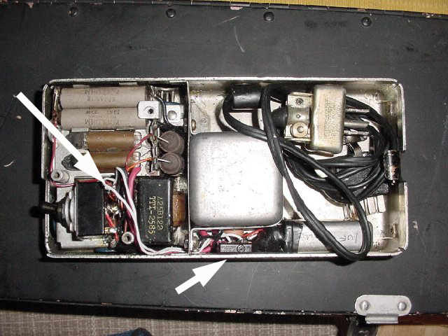
Left arrow points to the toggle switch. Right arrow points to the
small microswitch that was added. To spot you open up the cover of the
Filter Accessory Unit and push the switch.
Receiver Spotting Modification:
You may enable receiver spotting by modifying the wiring on the Filter Accessory Unit. It will be necessary to temporary jumper terminal 5 of the S301 toggle to provide High Voltage to terminal 6 of the toggle switch. Use a momentary push button switch such as a small micro switch. In the photo of the Filter Accessory Unit the white "spotting" wires are going to the toggle switch, Terminals 5 and 6 on the toggle switch are the ones closest to the VR tubes.