The progrock2
by "QRP labs" is a very versatile crystal substitute.

Initial Testing
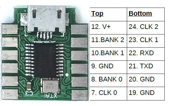
Connections
Power
Programming
Test Board
Output Voltage
Crystal Box
Military Radio
Misc
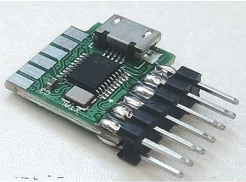
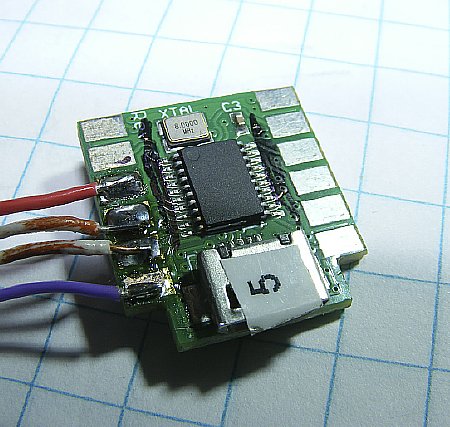
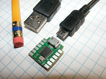
The
tiny Progrock2 board has the capability of being programmed with 24 frequencies.
Frequency range 2 kc to 200 Mcs.
Configuration Utility Screen
A total of 24 frequencies can be programmed in 8 "Banks."
![]() I recommend reading all of the QRP Labs info and downloading their manual
(PDF) then come back to this page. Purpose of this page is to provide
additional info.
I recommend reading all of the QRP Labs info and downloading their manual
(PDF) then come back to this page. Purpose of this page is to provide
additional info.
If
all else fails RTFM.
https://qrp-labs.com/progrock2.html (scroll down the page)
Initial Testing
 You can test your board immediately as it is shipped with
three (3) frequencies programmed. You do not need additional software
or a terminal program for initial testing.
You can test your board immediately as it is shipped with
three (3) frequencies programmed. You do not need additional software
or a terminal program for initial testing.
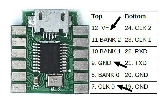
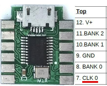
Initial
testing. Power up with V+ and a ground.
A preprogrammed 10Mc 3.3V PP
signal output should be available from the CLK 0 pad. In a hurry to power
up ? You can plug in a USB to Micro cable to supply the necessary V plus.
Just monitor the CLK 0 pad for output.You do not need the software as
you are just using the power from the USB connector.
Use a scope,
a counter, or near by receiver to check for output.
![]() It is advised to review all of this page prior to testing. Connection
and power suggestions are below.
It is advised to review all of this page prior to testing. Connection
and power suggestions are below.
 Do not allow the V+ pad to come in contact with the BANK 2 pad.
These pads are right next to each other on the Prog
board. Be careful with connections otherwise you could send the board
South. Been there and done that.
A voltage is never conneted
to a BANK pad. The BANK pads are used for frequency selection and are
activated by grounding.
Connection
info below.
![]() Do not apply 12 volts power to the board for extended periods.
Try and keep voltages in the 5 to 8 volt range. More
power info in the Power section below.
Do not apply 12 volts power to the board for extended periods.
Try and keep voltages in the 5 to 8 volt range. More
power info in the Power section below.
Connections
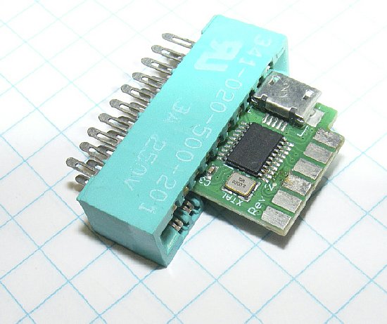
A multi
pin Edge Connector can be used for testing but be careful.
Edge Connector Specs : Connector Pitch is a measurement from center of one contact to the center of the next contact. The smaller 2.54 mm =.1 inch will fit the Progrock2.
The Progrock2 can utilize a 12 pin edge connector however most of the pins may not be used. Most 12 pin edge connectors will need a slot cut in the end of the housing to accommodate the board. Some edge connectors have contacts that "grab" the board better than others. Play with it or just solder direct to pads.
A edge connector with more than 12 pins can be used for temporary testing. Be careful.
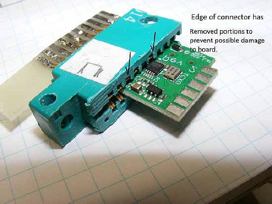
![]() Some
edge connectors may have contacts that allow the Progrock2 board to be
inserted too far into the body of the connector and do possible damage
to the Progrock2 surface mount components. Trimming the top of the edge
connection housing may prevent damage.
Some
edge connectors may have contacts that allow the Progrock2 board to be
inserted too far into the body of the connector and do possible damage
to the Progrock2 surface mount components. Trimming the top of the edge
connection housing may prevent damage.
.jpg)
2.54 mm / .1 inch. 12 pins - two rows of 6.
A notch had to be cut in the end of the 12 pin connector.
12 pin edge connector that
has been modified with a "Notch" on the end of the housing.
Make sure that the pads on the board line up with the edge connector contacts.
A test connector with minimum connections: Power, Ground, and Output.
![]()
A piece of plastic scrap was added as a spacer to assist in horizontal alignment.
QRP Labs Photo
The QRP labs manual offers several mounting options.
Solder connections can always be used.
![]() As
stated in the manual the three (3) CLK frequency outputs are not buffered
and are connected direct to the Progrock2 synthesizer output pins. You
can connect direct to the CLK output pads when there are no voltages involved.
Usually in a transmitter circuit you want to have a isolation capacitor.
I recommend that you use series capacitors on all three CLK outputs for
protection insurance.
As
stated in the manual the three (3) CLK frequency outputs are not buffered
and are connected direct to the Progrock2 synthesizer output pins. You
can connect direct to the CLK output pads when there are no voltages involved.
Usually in a transmitter circuit you want to have a isolation capacitor.
I recommend that you use series capacitors on all three CLK outputs for
protection insurance.
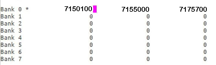
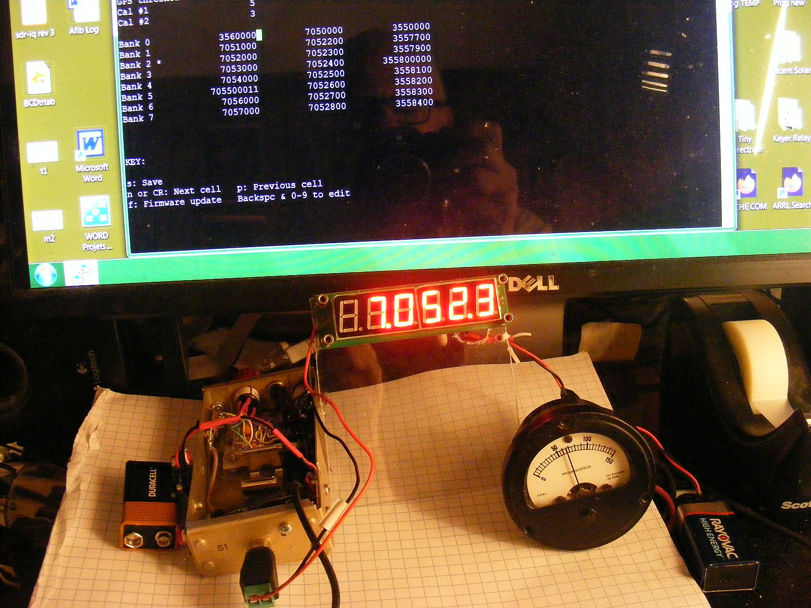
Typical
Screen Display during programming.
A
total of 24 frequencies can be programmed. A
"Bank" contains three (3) frequencies.
Bank
0 with three (3) frequencies is shown above.
Each individual frequency output in a Bank line is
available on the three (3) CLK pads.

Q.
How do you select one Bank? I see 8 Banks listed.
A.
The Banks are selected via BCD switching by grounding a BANK pad on the
Prog board.
Q.
What is BCD?
A.
Binary Coded Decimal.
Q.
Bad news. This is too complicated.
A.
Well the good news is you can have 3X8=24 frequencies available with a
single board.
Q.
How do I select BANK 0?
A.
Do nothing.
Q.
Once I select a BANK what then?
A.
The three (3) BANK frequency outputs are available on the Progrock Board
pads labeled CLK 0, CLK1, and CLK2.
Q.
How do I select one of the three frequencies in a BANK?
A.
By connecting to a CLK pad. Select 0, 1, or 2.
Q.
I just need one frequency.
A.
OK, just apply power and look for output on Bank 0
Q.
This is still to complicated. I rather just use crystals.
A.
Good for you.
Extra Questions;
Can I key the board for CW?
A. Yes by rapidly
grounding a Bank. Key back and forth.Program "0" in one of the
Banks.
Q.
How do I switch from transmitt to receive?
A. Key the board
back and forth between a active frequeny and a "0" in one of
the Banks.
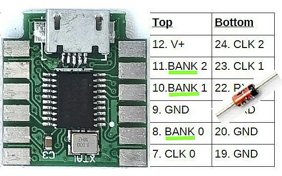
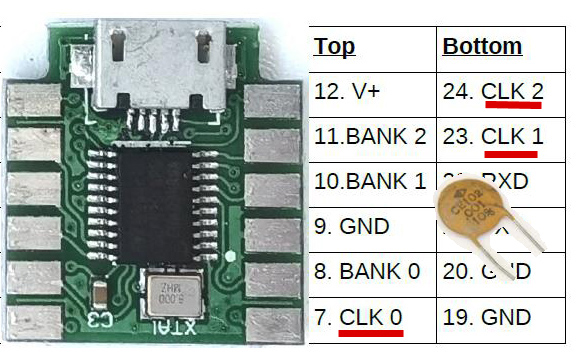
The
BANK pads are grounded to provide BCD coding to select one of the
8 banks of 3 frequencies.
Ground a
single pad or multiple pads for selection. - there are no voltages involved.
Use of a switching diode in
your ground circuit to select a BANK - will give you voltage protection
just in case.
This is not mandatory as normally
you are just applying a ground but may save your chip while your are testing
etc.
Confused yet? If
in doubt RTFM.
The BANK pads are grounded to provide a BCD signal for BANK selection.
No external voltages should be involved.
Power
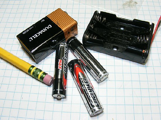
The
Progrock2 can accept a wide variety of DC voltages for power.
Three (3) AAA batteries can supply 4.5V which
is well above the minimum required.
The Progrock board
has an on board voltage regulator for inputs between 3.5V and 12V.
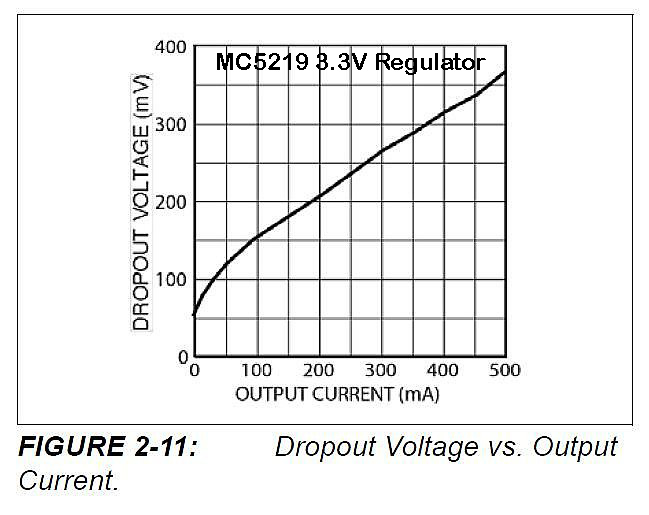
The Progrock2
has an on board 3.3V "Low Drop Out"voltage regulator. It can
operate on low input voltages close to 3.3V and and has a maximum of 12
volts. The Progrock2 has a typical input current of 40 to 50 mA. Using
50 mA the Progrock2 two could utilize a input voltage as low as 3.305
volts.
The
Maximum Progkrock voltage input is 12 Volts IAW the MC5219 data sheet.
BUT DO NOT APPLY 12 Volts to the Progrock2 for an extended period.
Several users have lost the on board regulator as it over heated.
When using 12 volts use a dropping resistor.
KA7OEI was one of the first to warn others of
this voltage problem. He suggested using a 1/2 watt resistor of 120-150
ohms when using 12 volts. KA7OEI also suggests that at even 9 volts a
resistor may be necessary.
![]() Consider
using using 5 volt regulator to supply voltage to the Progrock.
Consider
using using 5 volt regulator to supply voltage to the Progrock.
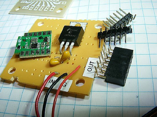
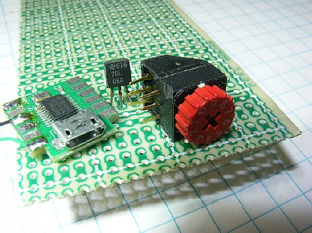
When
using a perf board consider installing a 5 volt regulator.
Q.
What happens when I use the USB cable for power but have a 5 volt regulator
wired to my Progrock2 board. Will it still work?
A. Yes the
Progrock has its own internal regulator. Do not power up the external
regulator at the same time.
Q. What
happens if I am powering the Progrock2 with a 9V battery and accidentally
power it through the USB cable at the same time?
A. You
will have a voltage conflict. See quote below from the Progrock2 manual. (Version
1.00b)
"Care should be taken when powering ProgRock2 directly from the USB cable (see below), and using a power supply connected to +V at the same time. The USB cable +5V will power ProgRock2 via an onboard diode, resulting in about 4.4V supply to ProgRock2. If you have connected an additional external supply voltage to ProgRock2, and that is less than 4.4V, then your external supply will fight with the USB voltage, potentially drawing excessive current through the onboard diode. 3.3V"
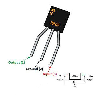
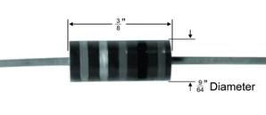
The
78L05 can save you perf board space. It does get warm with 12-14 volts
input.
Consider
a resistor in series. 12 Volts you can try a 100 ohm resistor in series
with the
input. When using the Progrock on a variety
of voltages the 100 ohm will suffice.
Progrock2 Current Consumption: Current can vary depending on frequencies
programmed and number of slots used.
Using
a USB source (5 volts) expect to draw approximately 45 mA. Draws approximately
35 mA at 12 volts.
The Progrock2 board is programmed via a standard USB micro cable.
 When you insert the connected cable into your computer USB you should
get a "Device Connect" notification. No drivers or additional
software will download from the Progrock2 board.
When you insert the connected cable into your computer USB you should
get a "Device Connect" notification. No drivers or additional
software will download from the Progrock2 board.
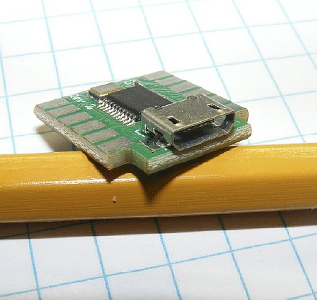
The connector and the board are very robust and have survived my work bench.

The Terminal Program "Putty" can be used to program the board.
Please go to the QRP Labs site and download the "Manual" for
the Progrock2.
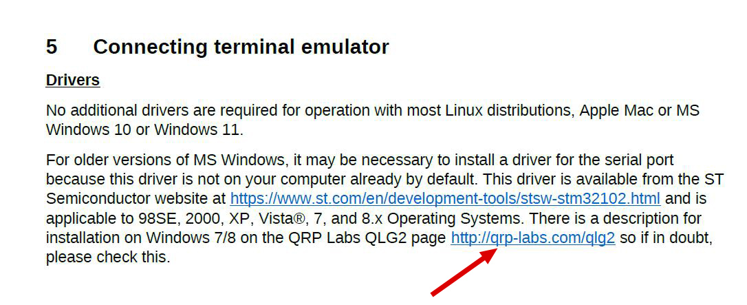
Review
Section 5 "Connecting Terminal Emulator".
![]() On
older versions of windows there can be a driver problem. I say again RTFM.
On
older versions of windows there can be a driver problem. I say again RTFM.
In Section 5 the first paragraph provides links for users of older windows.
CLICK to enlarge
When using an older version of Windows be sure and review info by Alan G4GFQ
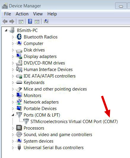
PuTTY will need a COM port identification.
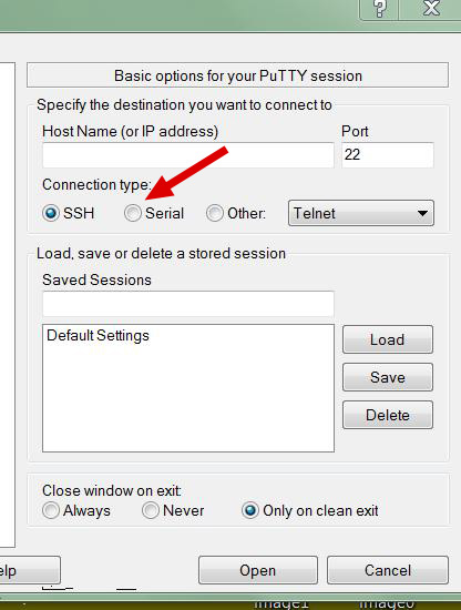
Be sure and select "Serial"
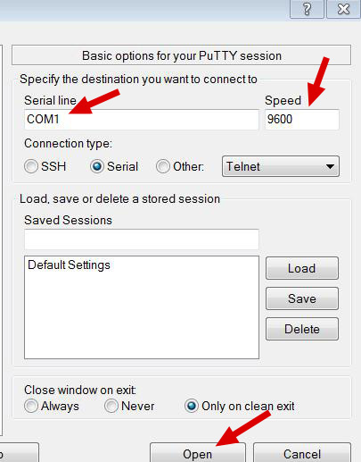
Change the COM port and Speed if necessary. Then Open.
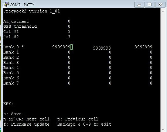
Open
screen shot. Note that the Progrock has BANK 0 programmed.
You can look for output on any CLK pad of 3.3V
PP. Or monitor on a nearby receiver etc.
![]() Zero out any unused cells. Don't leave one blank.
Please read the manual.
Zero out any unused cells. Don't leave one blank.
Please read the manual.
When the board is initially powered you should be able to see an output on the CLK
Pads. 3.3V Peak to Peak.
Test Board and BCD Bank selection
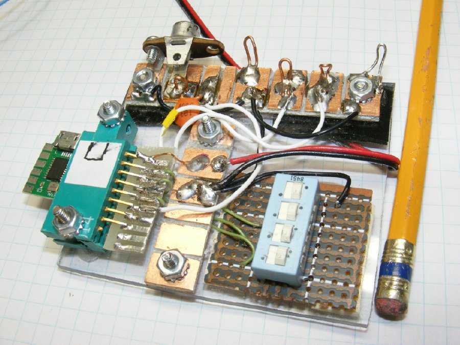
A
"Junk" box test board
A
quick test board using a junk box edge connector. Note the use of a DIP
switch
for BCD coding to select a BANK. Only
three (3) positions are needed on the DIP switch.
The
solder pads at the top provide test point for the 3 CLK outputs.
Total
of 8 BANKS of frequencies.
The board output frequency reverts to Bank 0 when a BANK is not selected.
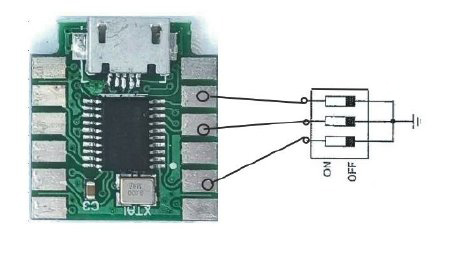
DIP
Switch wiring for BANK selection.
DIP switch BANK selection. Frequency BANKS
are selected by grounding "Bank" pads.
(No selection: Board reverts to BANK 0 BANK
0 frequencies are selected.
Ground BANK 0: Generates a BCD of 1 BANK
1 frequencies are selected
Ground BANK
1: Generates a BCD of 2. BANK 2 selected.
Ground BANK
0 and 1 = BCD of 3
BANK 3 selected.
Ground BANK 2 =
BCD of 4 ETC.
Ground BANK
0 and 2 = BCD of 5
Ground BANK
1 and 2 = BCD of 6
Ground BANK
0, 1 and 2 = BCD of 7
Ground
a "Bank" pad(s) for BCD generation and Bank selection.
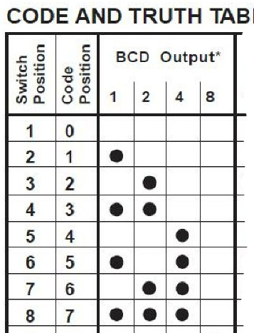
The Progrock2 board uses code positions 0 thru 7 for Bank selection.
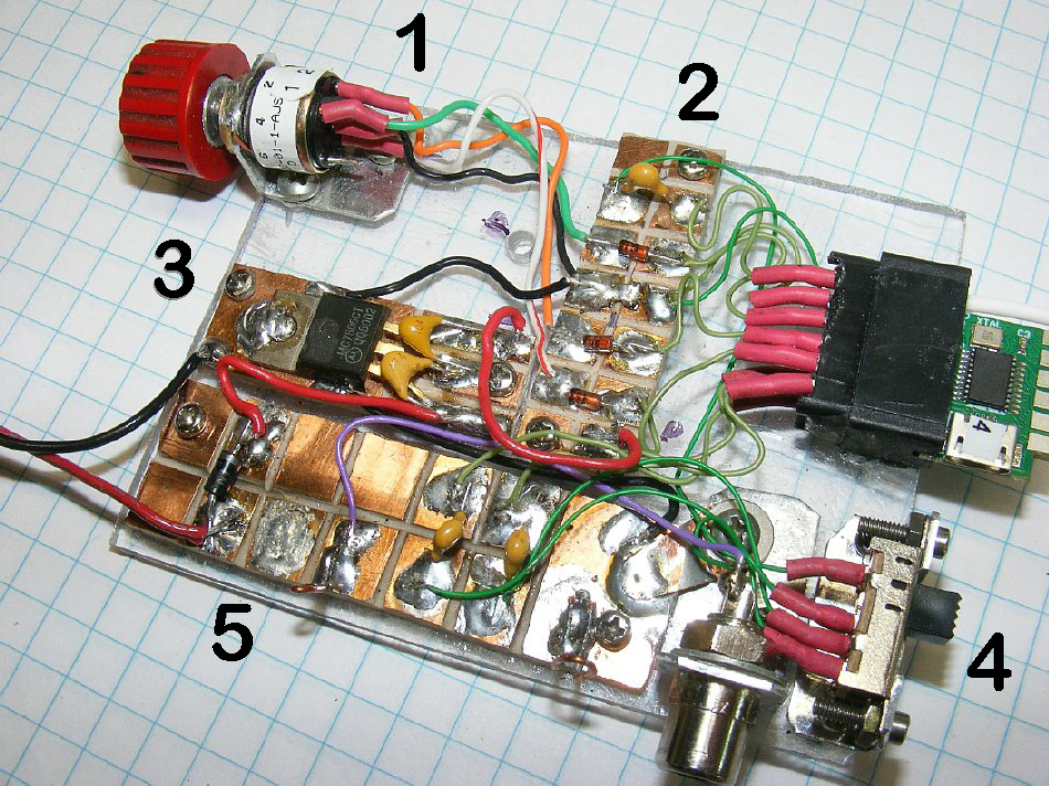
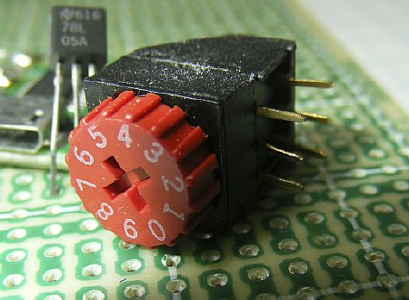
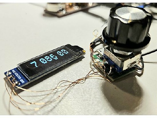
Another Test Board version with a 12 pin
edge connector and phono jack output.
1.
Rotary BCD switch which replaces the DIP switch.
2.
Solder pads for the edge connector.
3.
Voltage regulator.
4.
Three (3) position slide switch for CLK outputs.
5.
Power In and CLK outputs.
With
this test board you can select 24 frequencies. (3 X 8).
Saturday
night project.
The
rotary BCD switch makes it easy to select a frequency and switch back
and forth.
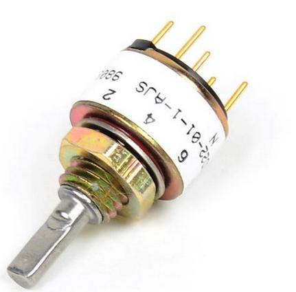
The Grayhill series have adjustable "stops" or they can
also be configured for continuous rotation.
BTW you can take a Grayhill 16 position switch and choose the
number of positions that are active.
Example: positionss 3,4, and 5.
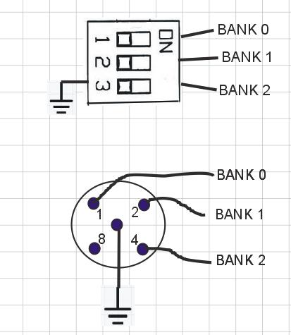
BCD Switch wiring.
Smaller BCD rotary switches for PC boards are available.
Thumb wheel allows easy selection.

CLICK
to enlarge "Proto
Supplies" photo
Position
"0" no pins are shorted to ground and Bank 0 is selected.
Position "1"
pin 1 grounds " Bank 0" Pad. BCD of 1 is selected
Position "2"
pin 2 grounds "Bank 1" Pad. BCD of 2 is selected
Position "3"
pin 3 grounds "Bank 0 and Bank 1. BCD of 3 is selected.
etc,
Be sure and check the pin out diagram for your switch
and
confirm with a resistance
check.
Ground BANK 0: Generates a BCD of 1 BANK 1 frequencies are selected
Ground BANK 1: Generates a BCD of 2. BANK 2 selected.
Ground BANK 0 and 1 = BCD of 3 BANK 3 selected. ETC.
Ground BANK 2 = BCD of 4
Ground BANK 0 and 2 = BCD of 5
Ground BANK 1 and 2 = BCD of 6
Ground BANK 0, 1 and 2 = BCD of 7
Q. Can I monitor the Prog
output frequency with a counter while running PuTTY?
A. Yes
Q. Why did you monitor the current.
A. I tried to determine which combination
of frequencies would alter the current.
Q. What did you find out?
A. There were many variables and it
got too complicated. Maximum increase was about 2 mA.
Q. How much current does the basic
board consume at 5 volts?
A. About 40 mA.
Q. When using a 5 volt regulator will
the current increase?
A. Yes a couple of mA.
![]() "Frequencies
set to zero cause the corresponding Si5351A output to simply be switched
off."
"Frequencies
set to zero cause the corresponding Si5351A output to simply be switched
off."
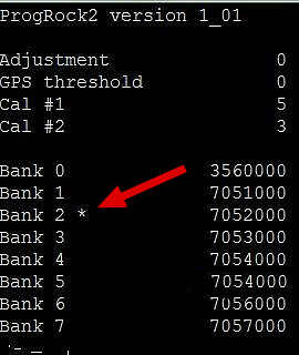
The * indicates your BCD selection.
Output Voltage
The highest output voltage from the Prog
board will be around 3.3V PP
![]() 3.3V PP may not be enough drive for older transmitters.
3.3V PP may not be enough drive for older transmitters.
CLICK
to enlarge Photo
by Frostburg.edu
The 1:2 circuits were the most predictable.
Here
is a link to Frostburg.edu on construction.
https://www.frostburg.edu/
1:2
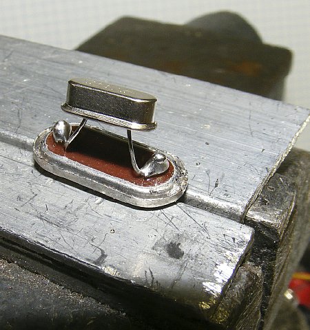
Balun mounted on a text fixture.
I played with different baluns. I started out
big and then used smaller toroid forms.
Keep
leads short. Especially on the output due to capacitance loading.
Hams
suffer from CDS and won't wind a coil.
Q. Did the baluns provide the necessary Peak to Peak voltages?
A.
Yes and NO.
Q.
Why not in some cases?
A. I could not properly match the impedance's.
Q.
How much voltage increase did you obtain?
A.
It doubled or tripled under no load conditions.
Q.
Did you try a 3 wire 1:3 Balun?
A.
Yes but see next question.
Q.
Did you get enough voltage increase for tube type oscillator circuits?
A.
No. I started looking at small RF amplifiers.
Several Progrock2 users have used small
step up transformers.
Look
at Ron NU6F's MAB wiring in the "Military: section of this page.

CLICK to enlarge
Check this site for parts and info.
https://kitsandparts.com/index.php
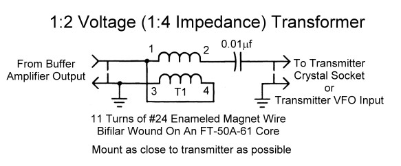
1:2
"Voltage" Balun.
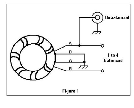
A nice wiring sketch by
N1HFX. Compare it to the schematic below.
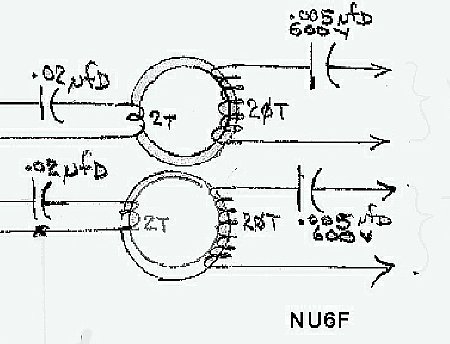
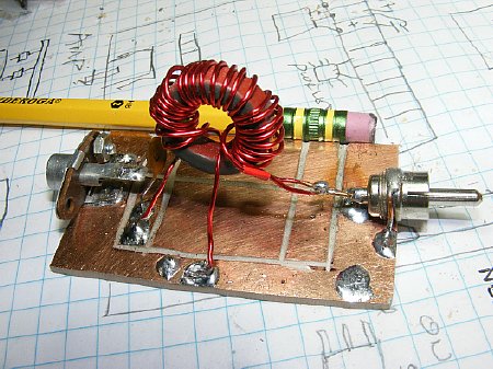
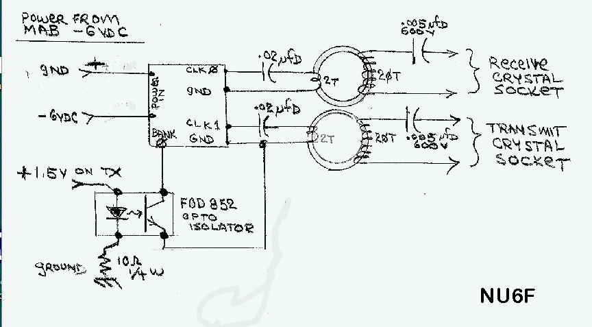
Ron NU6F used small toroid transformer to increase voltage for
crystal socket matching and injection.
A Full schematic is shown below in the "Military" section.
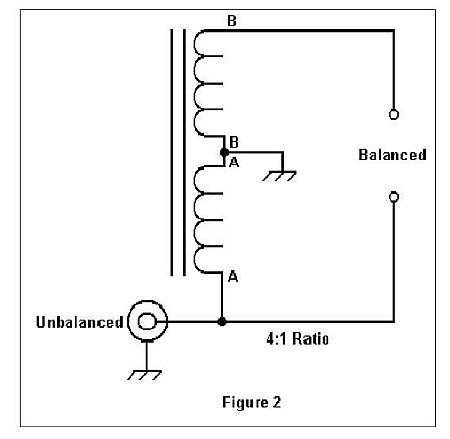
N1HFX 1:2 Voltage Balun
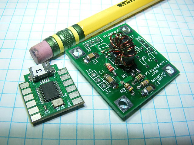
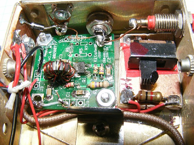
Progrock2
and a small RF amplifier.
The RF amplifier shown above is a "Kit"
by W8DIZ Parts.
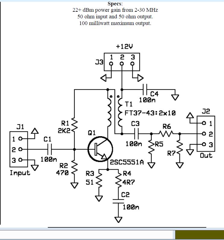
![]() Click here for the "Wideband RF Amplifier
Manual".
Click here for the "Wideband RF Amplifier
Manual".
The RF Amplifier
uses some Surface Mount Components to reduce board size.
Voltage gain is around 10 - 12X.
Q.
I hate kits. They are a PITA.
A. It is a small
kit, you will only be in pain a short time.
Q. How much voltage gain
?
A. Around 10 to
12X
Q. What is the input
impedance?
A. Approx 50 ohms.
Q. I hate SMT components.
A. Good grief -
there are only 4 capacitors and a transistor.
Q. I do not have
a soldering iron for SMT's.
A. Just use a narrow
tip and medium heat.
Q. I hate winding
coils.
A. CDS is very common
among hams.
Q. Can I use a 9
volt battery for power?
A. I've used 9 to 12
volts.
Q. Are there any other
amplifier boards?
A. Yes. Try searching
for VFO or DDS amplifier.
CLICK to enlarge
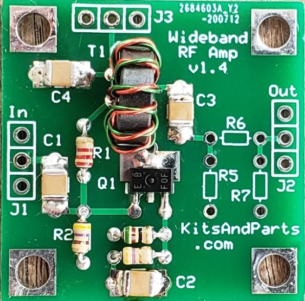
R5, R6, and R7 are not included with the kit.
Solder a jumper in position R6.
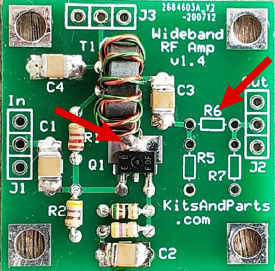
![]() Install a jumper wire in the R6 position.
Install a jumper wire in the R6 position.
Be sure and solder the collector of
the transistor. Resistors can
be
added at R5, R6, and R7 for attenuation.
The four (4) mounting holes are grounded.
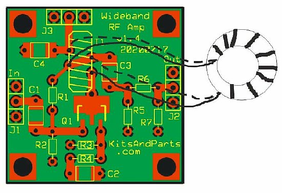
Coil shown off the board for wiring illustration.
Installation of the coil has to be correct for proper coil phasing.
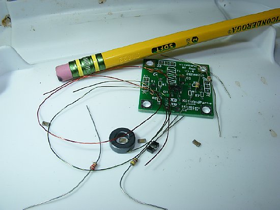
4 Caps, a couple of resistors and a transistor.
Wind a 10 turn coil and FINI a amplifier for the Progrock2.
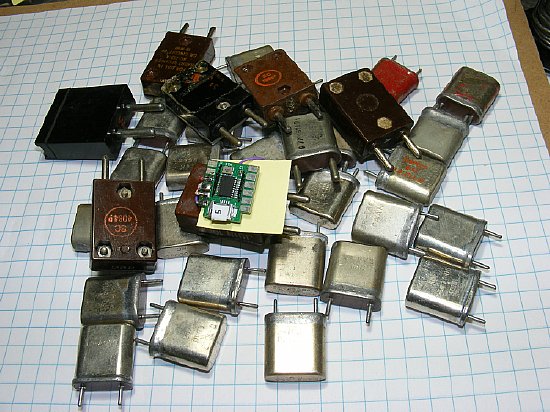
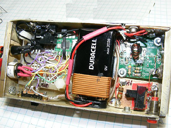
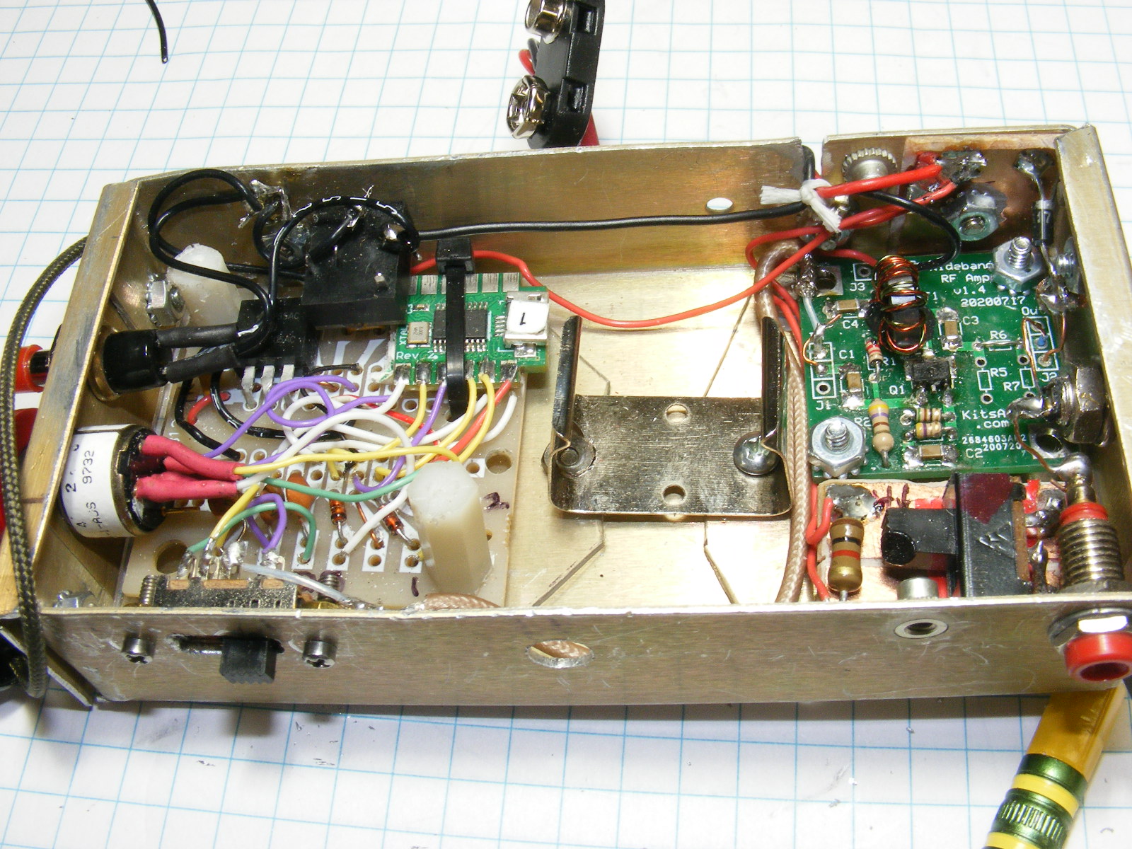
Crystal Box
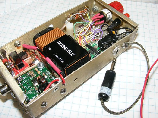
I call it
my "Crystal Box". A total of 24 programmed frequencies.
A small Amplifier board is installed to increase the output
voltage.
A
"shorted" plug is used for power On and Off.
USB cable attached.
The "Box" can be reprogrammed with different frequencies as need arises.
A Saturday Night project.
The battery can be removed
and the battery cable connected to a
external source such as a 12 volt pen cell holder.

This pack has the standard 9V connector.
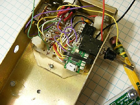
A Perf board is used to mount the Progrock and a 5V regulator, caps, and diodes.
When mounting make sure that the micro connector is accessible.
A 3 position
slide switch was mounted on the left for "CLK" selection.
An 8 position BCD rotary "BANK" switch is
mounted at the top. 24 total channels.
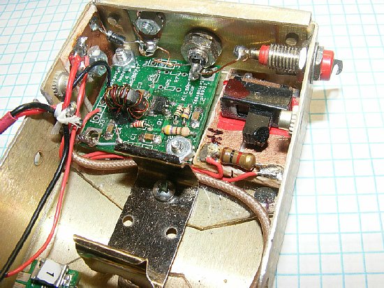
A
W8DIZ amp was mounted in the other end. A slide switch
selects High and Low voltage for the W8DIZ amplifier.
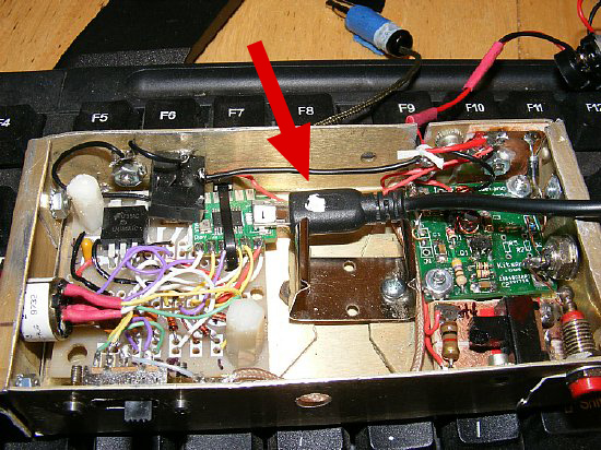
Another view of the W8DIZ amplifier.
A Phono socket is used for
the main RF out. In addition a output tip jack is mounted at the upper
right.
A Hi/Lo toggle switch
is mounted below it.
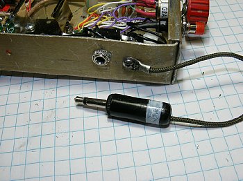
I use a "shorted" plug as a switch for positive control.
CLICK
to enlarge
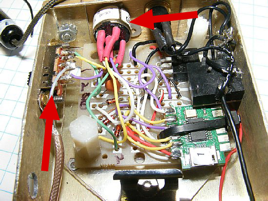
A 3 pole slide switch is mounted on the left for "Bank"
selection.
A tip jack and Phono jack are used
at the output.
24 Frequencies can be
selected via the 8 position Rotary switch
and the 3 position "CLK" Slide switch. Suggested wiring
diagram below.
 A
short demo video of the Rotary BCD switch.
A
short demo video of the Rotary BCD switch. 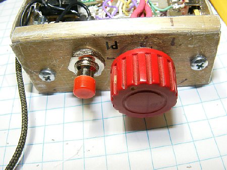
The 8 position BCD rotary switch
is mounted on the end.
The Red push button
overrides the power switch.
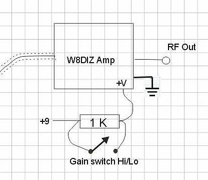
By switching a 1K resistor In and Out - High and Low voltage gain
can be selected for the W8DIZ amplifier.
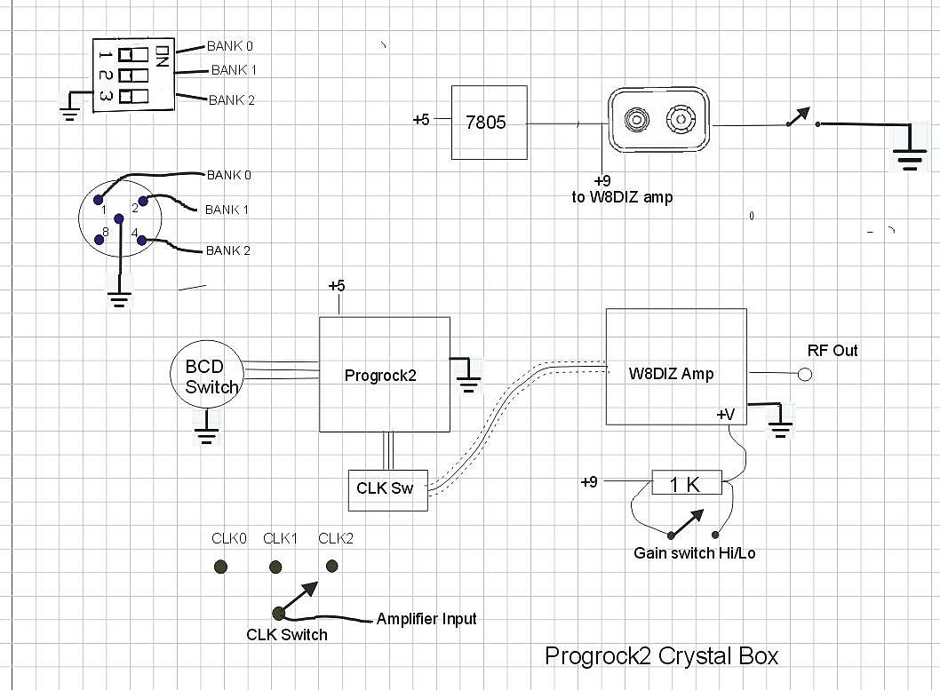
CLICK to enlarge for a wiring diagram.
Military Radio
N3KCB did a nice job of using the Progrock2 in a TRC-77. His documentation is excellent.
CLICK to enlarge
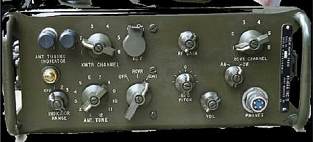
Ron NU6F offers this Progrock2 installation in a MAB. Note the use
of small toroid transformers.
He takes advantage of "Bank" selection when going from receive to transmit.

Here is Ron's Progrock2
MAB assembly. Note the 2 turn primary on the coil.
Misc
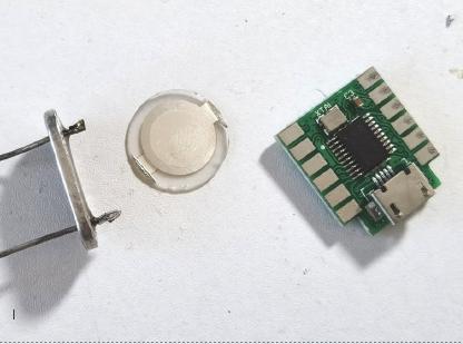
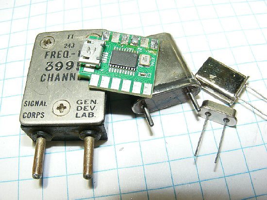
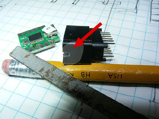
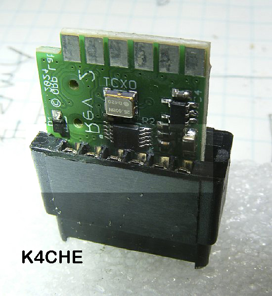
The
Progrock2 board can be mounted in a HC-6 holder.
Q. Why do this?
A. For unique applications.
Q. How do you get power?
A. Use one of the pins.
Q. How do you program the board?
A. It is done before inserting the
board.
Q. How do you change the frequency?
A. Once the board is encased you can't.
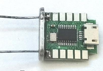
Q. I only see two leads, I need three.
A. Use the outer case for ground.
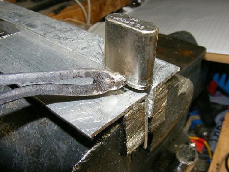
Open a HC-6 crystal holder
A large iron can come in handy or use a home made tip.
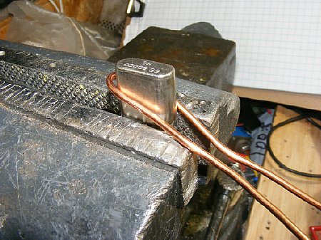
I restuff the HC-6 quite often.
A home brew soldering tip (#12 wire)
for my large 250 watt iron comes in handy.
QRP
Labs photo
The solder
pads on the Progrock2 are convenient for mounting
in a HC-6 holder.
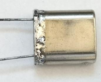
The pins are used for power and output. The case is ground.
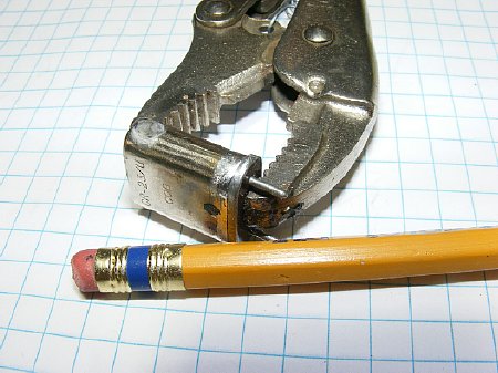
Adjustable pliers are used as a clamp to resolder.
HC-6 case for a crystal socket connector.
I often mount Chink crystals inside the HC-6 holder.
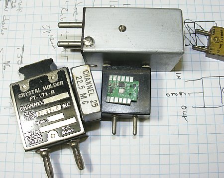
The Progrock2 can fit inside many of the crystal holders.
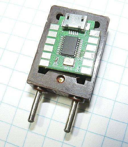
Its
a tight fit.
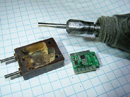
You can mill out the interior with a Dremel tool
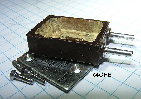
Use the cover for the ground connection.
Remove cover if you need to reprogram.
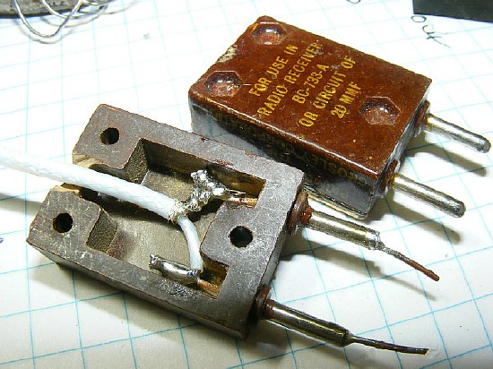
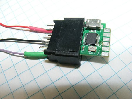
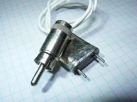
The FT-243 can be used as a Progrock2 cable plug for a crystal socket.
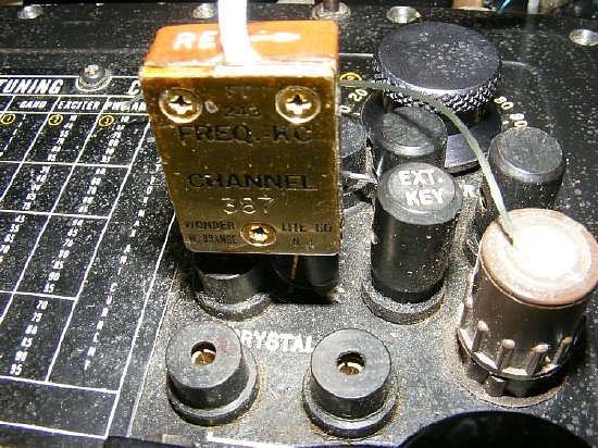
Here the Progrock2 plug is used on a GRC-109. Note: Just use the Grid
position of the crystal socket. Ground the other pin (shield) of the FT-243.
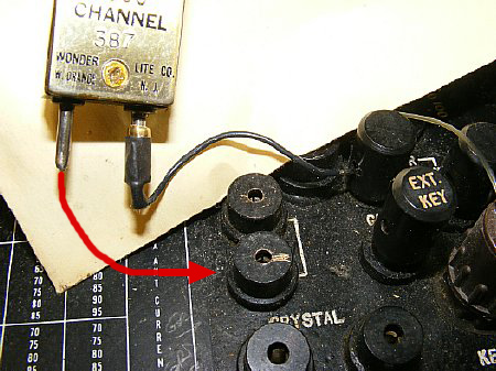
Ground one pin (shield) of the FT-243, the other pin plugs into the grid side of
the GRC-109 socket.
QRP Labs offers several VFO kits that also uses the Si5351
IC.