Polar Relay 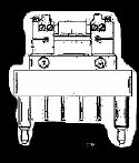 Testing
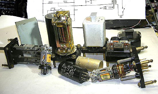
Polar relays have been used extensively in teletype circuits. All the relays shown here can be tested and adjusted with the circuit below.
.JPG)
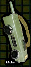
Some of the most popular relays. Show above are the 255, the Automatic Electric style, and the 314
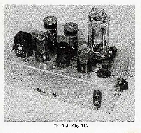
Photo:
Page 92, "RTTY A to Z" by W5VU, published by "CQ"
Technical Series.
Polar relays were popular as loop keyers in early TU's using 6SL7,6C5, and 6SN7 tubes. Later we substituted 12AX7, 6C4, and 12AU7 miniature tubes. The primary feature of the design was the filters composed of very high Q - 88 mH toroids. Construction required punching holes in a chassis, mounting components and tuning filters. Tuning the 88 mH filters usually involved using 60 cycle lissajous patterns. That was real radioing.
 www.
navy-radiocom has a very comprensive collection
of information on the RTTY mode and equipment.
www.
navy-radiocom has a very comprensive collection
of information on the RTTY mode and equipment.
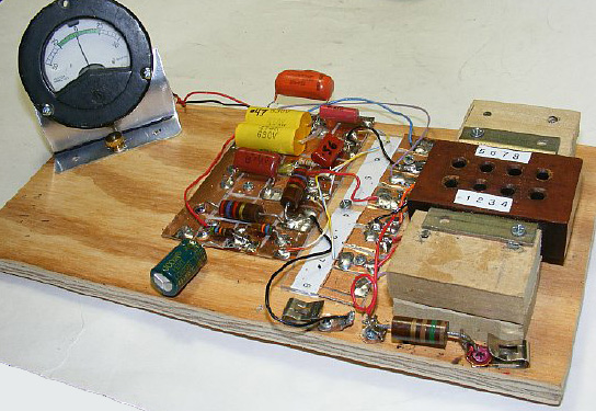
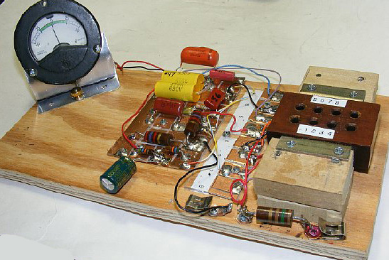
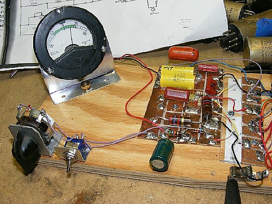
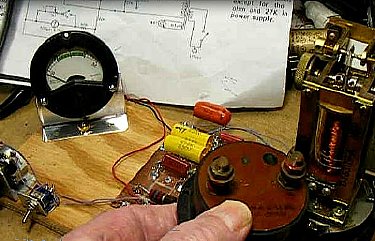
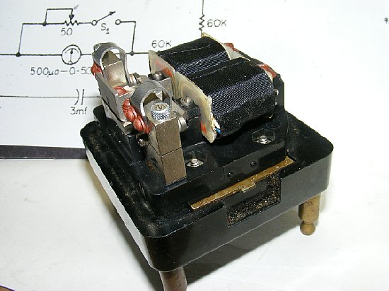
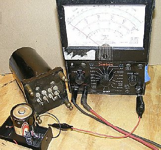
Polar Relay Test Set. Later I added a variable pot as a shunt for the sensitive 50uA meter.
Many thanks to "CQ" editor Rich Moseson, W2VU
for permission to present portions of the November 1960 Issue containing
the original schematic of the "Polar Relay Test Set".
There is a lot of valuable RTTY information available
in the "CQ RTTY" columns for the 1950-1960 time period.
Searchable index and individual issues are available:
https://hamcall.net/cq
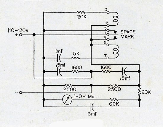
Polar
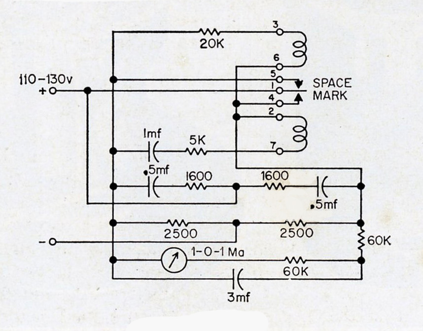
Relay Test Set
Original
schematic "CQ" Magazine November 1960 "RTTY" Column.
![]()
The
Polar Relay Test Set information was also published in the "CQ"
Technical series book "The New RTTY Handbook" by W2JTP.
January 1962.
It was assumed that the above version was powered by the local loop supply.
Another version with an on board power supply is depicted below.
I used the "Polar Relay Test Circuit primary to find out if a
relay was operational and to make small "Mechanical Bias"
adjustments to equalize the ON/OFF cycles. Any relay that can not
be set to zero with small Mechanical Bias adjustment will need
to go through a complete adjustment cycle to include Armature centering
and Contact adjustment. A lot of these relays have been "Ham Hacked".
The "Polar Relay Test Set" was again published a second time in the "CQ" Technical Series" book RTTY from A to Z by W5VU. 1970.
Note in this version that the meter was changed from a 0-1 mA to a more sensitive 500 uA meter and a on board power supply was utilized. In addition the sensitive uA (microamp) meter had a 50 ohm adjustable shunt that could be switched In and Out.
Mount the meter as far as possible away from the 255 relay mount to prevent
magnetic interference during adjustment. A shielded meter is best.
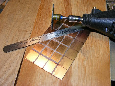
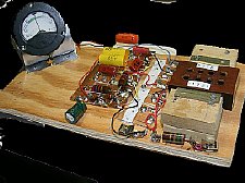
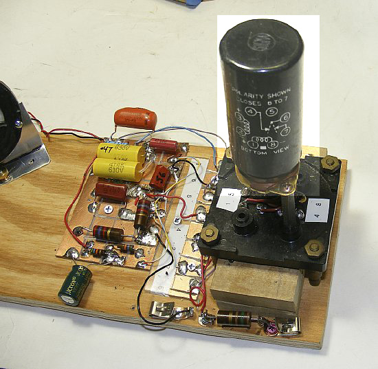
A quick way to fabricate a circuit is to use a PC board (copper clad) cut with small squares.
Mounting
parts on the individual squares makes it easy to experiment with the circuit.
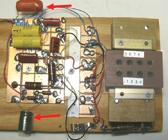
The top Red capacitor is a .22 (point two two) placed in parallel with
a couple of .47 caps used to adjust the frequency of the circuit to 22
cps. The large bottom capacitor is a 10 uF and is used across the meter
to dampen the movement of my 50 uA meter.
PARTS Info: I subbed two .47(point 47) caps and a .22 (point 22) all in parallel for the 1 mF "timing" capacitor. My meter was a 50 uA with a 10 uF damping capacitor. A meter shunt was not used at first but added later in order to detect larger off center (off zero) operations. I used a 600 ohm pot as a meter shunt which gave my 50 uA meter a range of 100 to 1000 uA.
My meter shunt was a 600 ohm pot and a toggle switch to allow insertion of the shunt. Besides if you have a variable pot to turn and a toggle switch to flip it makes you feel like you are doing some real "Radioing".
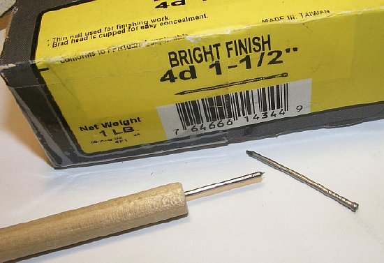
A 4d nail can be used to adjust the 255 relay. Make a tool with a wooden dowel.
![]() The power supply high voltage voltage is present
on all metal surfaces of the 255 relay regardless of armature position
or activity.
The power supply high voltage voltage is present
on all metal surfaces of the 255 relay regardless of armature position
or activity.
Exception:
The metal base plate is insulated from the upper section.
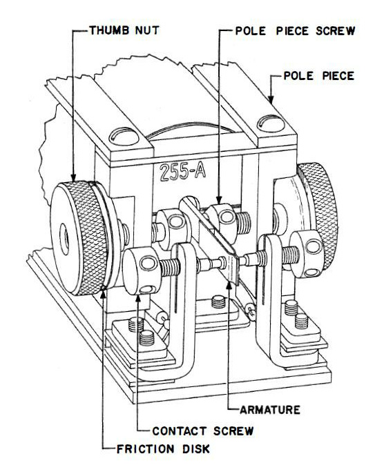
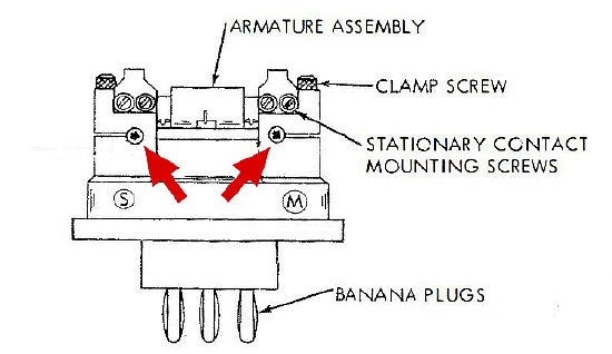
Most
255 relay contacts can be adjusted for equal On/Off time by adjusting
the Mechanical Bias via a Pole Piece. Loosen
the Thumb Nut first.
The idea is to adjust the "Mechanical Bias"and
to observe the meter for "Zero". Try to leave the Contact Screws
alone.
MOST
relays just need minor adjustment. But there are a lot of meters that
have been "Ham Hacked".
 Q.
With a sensitive 50 uA meter and the meter indicates slightly off center
isn't that a small amount of current indication to try and correct compared
to the amount of current in the circuit.
Q.
With a sensitive 50 uA meter and the meter indicates slightly off center
isn't that a small amount of current indication to try and correct compared
to the amount of current in the circuit.
A. It would seem that way. On some of the relays that I tested the meter (with a shunt) would read up to 500 uA and required considerable adjustment. The closer you get to "Zero" the better balance of On and Off time occurs.
Home
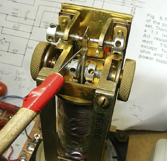
made probe
![]() You can try a tiny amount of pressure on the armature to test for "Pole
Piece" adjustment. A small amount of side pressure on the armature
creates instant "Mechanical Bias". Just barely touch the
armature with the needle probe.
You can try a tiny amount of pressure on the armature to test for "Pole
Piece" adjustment. A small amount of side pressure on the armature
creates instant "Mechanical Bias". Just barely touch the
armature with the needle probe.
![]() In the event the relay does not start a small amount of probe
pressure on the armature may get it started.
In the event the relay does not start a small amount of probe
pressure on the armature may get it started.
![]() The power supply High Voltage present on all metal
surfaces regardless of armature activity. Exception:
The metal bottom base plate is insulated from the upper section.
The power supply High Voltage present on all metal
surfaces regardless of armature activity. Exception:
The metal bottom base plate is insulated from the upper section.
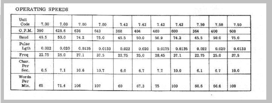
.jpg) TEST SPEED: Dovetron Company uses 1/2 (one half) the baud rate as the
speed for their square wave generator to create RY's. The military test
set the I-193 used a pulse generator of "22 milliseconds". Most
amateur RTTY ops are conducted at 60 WPM or a baud rate of 45.45. Try
setting the frequency of the Polar Relay Tester to approx. 22 cycles per
second.
TEST SPEED: Dovetron Company uses 1/2 (one half) the baud rate as the
speed for their square wave generator to create RY's. The military test
set the I-193 used a pulse generator of "22 milliseconds". Most
amateur RTTY ops are conducted at 60 WPM or a baud rate of 45.45. Try
setting the frequency of the Polar Relay Tester to approx. 22 cycles per
second.
CLICK
to enlarge
The
Operating Speeds chart from one of "Navy Radio's" files.
Test
Set Power Supply Voltage: A well adjusted relay should start and function
using the Test Set between 50 and 150 volts DC. It helps to power the Test
Set with a variable voltage power supply. 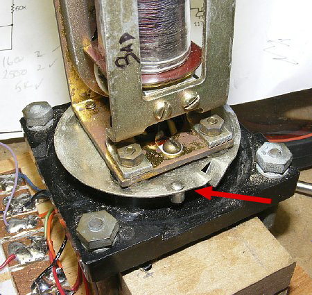
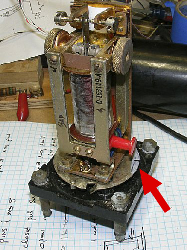
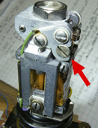
The
base plate (arrow is insulated from the upper relay section. Voltage is
present on the upper section.
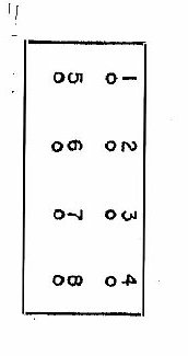
255
Base Bottom View looking at the pins.
Standard pin configuration. In the event your 255 pins are not marked, examine the base wiring and the #8 pin can be identified as it will not have any wires connected to it
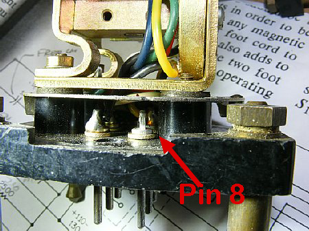
Pin 8 is bare. There are no wires connected.
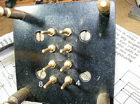
Bottom view of pins 8 and 4. Pins 5 and 1 are at the top.
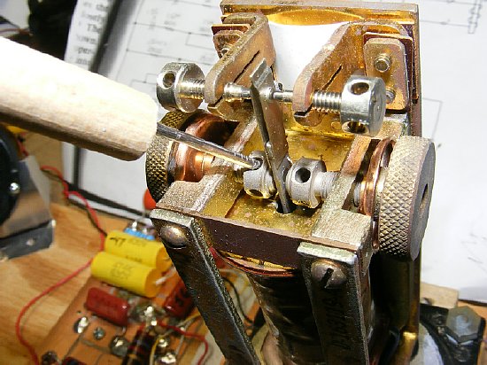
The "Nail Tool"
fits inside the holes on the Pole Piece Screws as well as the Contact
Screw holes. It is easy to make small adjustments.
Make small adjustments. Observe the meter to determine direction.
![]() When the relay is just a little out of Mechanical Bias adjustment turning
either Pole Piece should allow adjustment for equal ON/OFF periods and
a "Zero" indication on the meter.
When the relay is just a little out of Mechanical Bias adjustment turning
either Pole Piece should allow adjustment for equal ON/OFF periods and
a "Zero" indication on the meter.
Keep any unshielded meters away from the 255 during testing. Large tools also effect the field.
Q. Since the 255 relay is sensitive to external magnetic fields - why
was it not shielded with a metal cover?
A.
I don't have a clue.
Q.
What do you do for an audio output.
A.
Try tapping at various places in the Tester, use a .01 in series.
www.
navy-radiocom has a very comprehensive collection of information on
the RTTY mode and equipment.
https://www.navy-radio.com/rtty.htm
Here is a PDF on the 255 adjustment that was downloaded from Nick' site.

Here
is a couple of pages from a "CQ" article describing a condensed
method of 255 relay adjustment
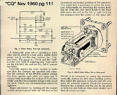
PDF
file below. Permission granted
from CQ magazine editor Rich Moseson, W2VU to publish part of the original
article. The article describes a condensed and simpler procedure for 'adjusting
the 255 relay.
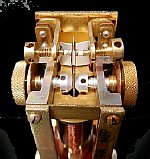
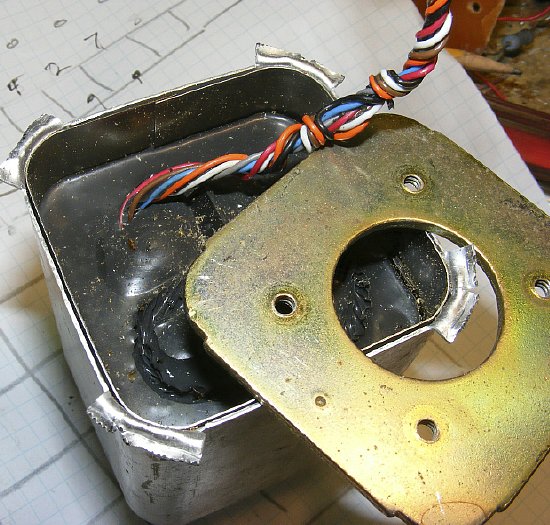
Automatic Electric style of relay. Cover removed. The AE can be tested in the Polar Relay Tester.
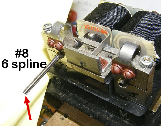
Magnetic Bias adjustment of the Automatic Electric Style Relay using a spline key.
Loosen
the "Clamp Screw"on top before attempting adjustment of the
"Magnetic Bias" screws.
CLICK
to enlarge
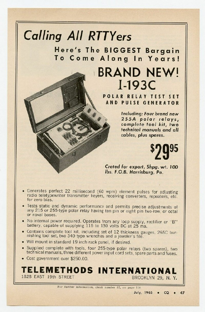
The
I-193 Test Set was a popular surplus item years ago. I would like to obtain
the manual or at least the schematic of the set.
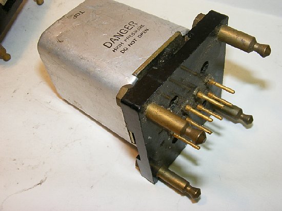
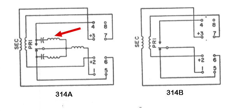
The 314 series has coil resistance's of approximately 140 ohms and will function and test in the Polar Relay Test Set.
Click
to enlarge
The "A" version of the 314 has "Contact Protection" which may interfere with keying characteristics.
The 314 is sealed, no adjustment.
255 Quick coil and contact check
Using
a D cell (1.5 volts) and a VOM you can determine if the 255 coils are
OK and run a contact check.
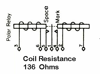
Procedure. Contacts 1 and 4 Check: Set Meter on X100 and connect meter to coil contacts 1 and 4 - if meter indicates that the contacts are closed then supply Negative voltage to pin 3 and Positive to pin 6 and contacts should open. If contacts are open then supply Positive to Pin 3 and Negative to Pin 6. Contacts will close.
Contacts
1 and 5 Check: contacts closed - then provide Positive to Pin 2
and Neg to Pin 7
Contacts are open reverse and put Negative voltage to Pin
2 and Positive voltage to Pin 7.
Use a 1. 5 volt battery for powering the
relay coils or use a 12 volt supply with a 1K dropping resistor.
An
Experiment
Simple
Modification
You can turn the Polar Relay into a NC/NO relay by up setting the magnetic field. Try placing a small magnet in various places on the relay frame. Try input on pins 3 and 6 and output on pin 1 and 4. Play with it.
Sigma Style Octal Relays
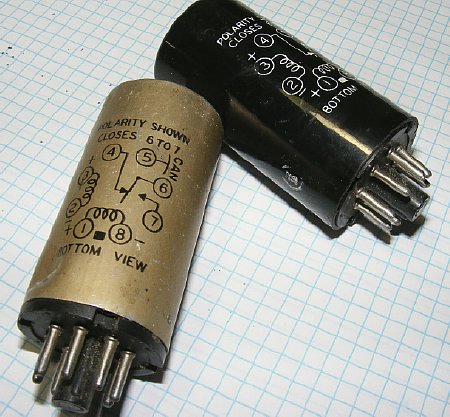
Octal version of the polar relays come in shielded and unshielded versions.
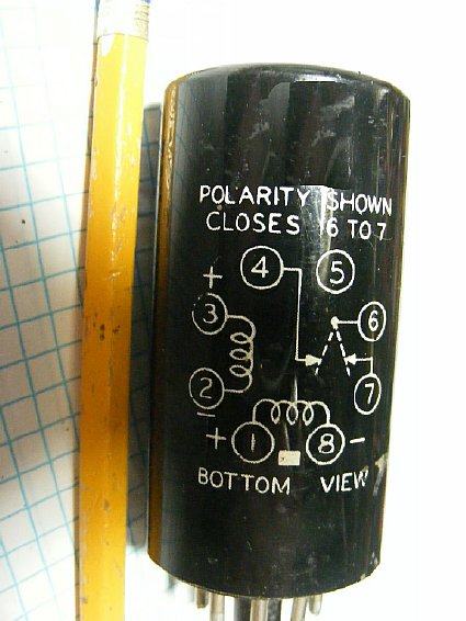
Pin
numbers of the coils and contacts are not the same as the 255 series.
These Sigma relays were a little strange. Contacts 4 and 6 are NC and
return to that state every time. The 255 series contacts will flip flop.
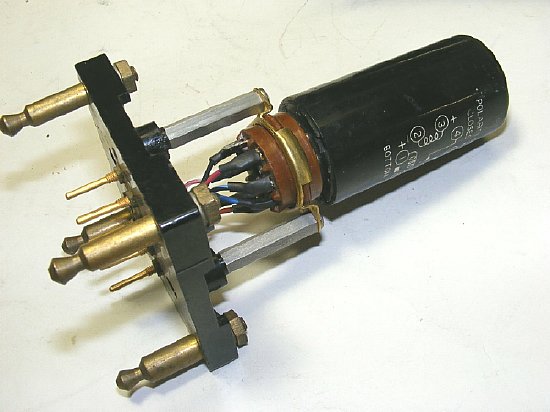
An octal adapter was fabricated from a "Ham Hacked" 255 Relay base.
The
smaller octal relays operate the same as the 255.
These Sigma relays were a little strange. Contacts 4 and 6 are NC and
return to that state every time. The 255 series contacts will flip flop.
Some of the Sigma series polar relay have 4K coils.
Mechanical Bias Adjustment