
PRC-6 Battery Box
Note: You have enough time to get your PRC-6 powered up in order to be at the Military Radio Collector Association Meet next September at Gilbert.
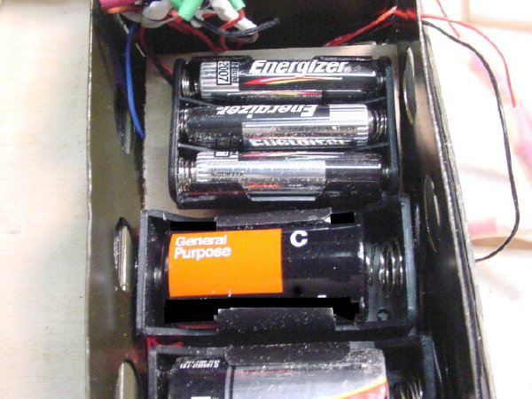
WARNING: I have had several reports of Energizer batteries overheating when used in parallel. Please make sure that the batteries that you use are fresh, same date code etc. I suggest testing them for equal voltages under load before using them in the battery pack. I would not mix different brands of cells. Some of the overheat reports resulted when the Energizer C cells was used. During periods when your PRC-6 is not used I would remove the pack from the radio.
UPDATE: May 2006, I have also experienced the same with C cells in a PRC-6 but they were not the Energizer brand but were cheaper batteries. One cell shorted out internally and drew the other batteries down which created a lot of heat.
Please read Energizer's Product Safety sheet at: http://data.energizer.com/PDFs/carbonzinc_psds.pdf
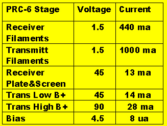
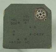
.JPG) Overview: The PRC-6 requires
two high voltages: 90 volts and 45 volts.
In addition it requires a filament voltage of 1.5 volts. A bias voltage
of 4.5 volts is also needed for the frequency control and audio circuits.
Off the shelf batteries will be used in a unique two tiered battery box
that is easy to construct, service, and is robust in construction.
Overview: The PRC-6 requires
two high voltages: 90 volts and 45 volts.
In addition it requires a filament voltage of 1.5 volts. A bias voltage
of 4.5 volts is also needed for the frequency control and audio circuits.
Off the shelf batteries will be used in a unique two tiered battery box
that is easy to construct, service, and is robust in construction.
 Basically
the box is in two tray sections, high voltage on the top and low voltages
on the bottom. The upper "straddle tray" holds the 9 volts batteries
can be removed for service. The "straddle tray" straddles and
fits on top of the C cells below. Simple spade type connectors are are used
between the trays..
Basically
the box is in two tray sections, high voltage on the top and low voltages
on the bottom. The upper "straddle tray" holds the 9 volts batteries
can be removed for service. The "straddle tray" straddles and
fits on top of the C cells below. Simple spade type connectors are are used
between the trays..
WARNING: Even though we are dealing with those harmless 9 volt batteries , when they are wired in series the voltage is over 90 volts and you can shock the xiss out of your self if you forget or get careless. Do not test the 90 volt battery string with your tongue.
: The
bottom sections holds 4 "C" cells wired in parallel and the
4.5 volt bias pack consisting of 3 AAA batteries. Don't worry about the
small size of the AAA batteries, they will hold up as the bias circuit
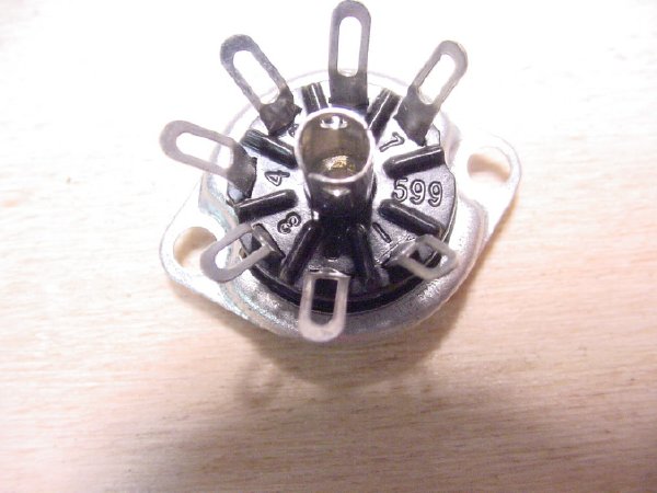
draws less then 10 microamps. A standard 7 pin vacuum tube* socket
is used for the pack connector.
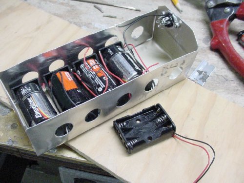
The
bottom sections holds 4 "C" cells wired in parallel and the
4.5 volt bias pack consisting of 3 AAA batteries. Don't worry about the
small size of the AAA batteries, they will hold up as the bias circuit
draws less then 10 microamps. A standard 7 pin vacuum tube* socket
is used for the pack connector.
* That hollow thing that lights up.
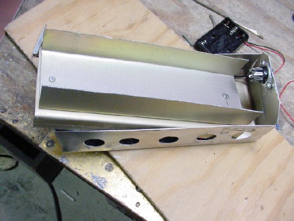
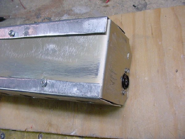 The
"Main Tray"consist of a long tray with attached sides. This view
is of the bottom of the main tray showing the bottom over lapping edges
of the sides.
The
"Main Tray"consist of a long tray with attached sides. This view
is of the bottom of the main tray showing the bottom over lapping edges
of the sides..JPG)
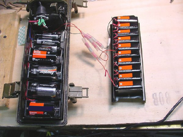
 Comparison
of the original battery to the "main tray" assembly. Arrows point
to tie points for providing strain relief for the wiring. The fabricated
sides are shown but are not attached yet.
Comparison
of the original battery to the "main tray" assembly. Arrows point
to tie points for providing strain relief for the wiring. The fabricated
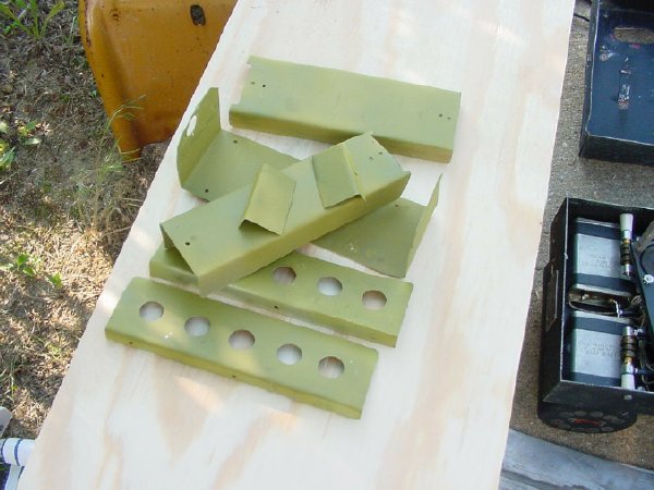
sides are shown but are not attached yet. Shown are the dimensions for the main tray, the idea is to make
the tray as large as possible and fill up the radio, this leaves more room
for the batteries. So make this tray as
wide and as long as possible. Fabricate all
of the sections from .025 aluminum sheet available from your local home
supply store. If you don't have a sheet metal brake see my "BC-611
battery box" for bending techniques using a bench vice.
Shown are the dimensions for the main tray, the idea is to make
the tray as large as possible and fill up the radio, this leaves more room
for the batteries. So make this tray as
wide and as long as possible. Fabricate all
of the sections from .025 aluminum sheet available from your local home
supply store. If you don't have a sheet metal brake see my "BC-611
battery box" for bending techniques using a bench vice. 
Sides for the "Main Tray", You might want to round the top corners after bending.
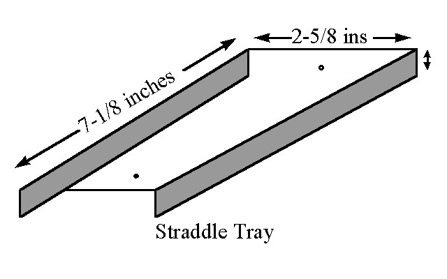
The "Straddle Tray" will fit down inside the "Main Tray". Notch out the front of the tray to allow room for the wiring.
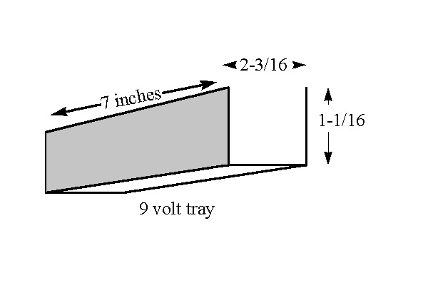
The U shaped "9 volt tray" holds 10 of the 9 volt batteries and is attached to the top of the "Straddle Tray".
The "9 volt tray" attaches to the top of the "Straddle Tray".
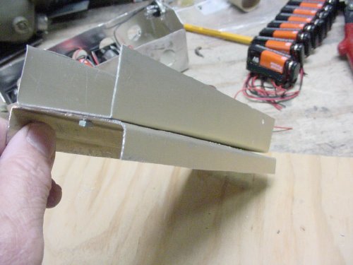
 The
upper straddle tray assembly will slide into the lower assembly. The rear
cover for the radio keeps everything in place.
The
upper straddle tray assembly will slide into the lower assembly. The rear
cover for the radio keeps everything in place. 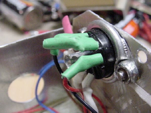 A standard 7 pin socket is used for the connector. Notice the
"Stop Nuts" used for the assembly. A hot air gun will be used
on the heat shrink to shrink it.
The connector is mounted in the top of the main tray. There is room beside
the C cell holders for a distribution board and the AAA bias battery holder.
A standard 7 pin socket is used for the connector. Notice the
"Stop Nuts" used for the assembly. A hot air gun will be used
on the heat shrink to shrink it.
The connector is mounted in the top of the main tray. There is room beside
the C cell holders for a distribution board and the AAA bias battery holder.
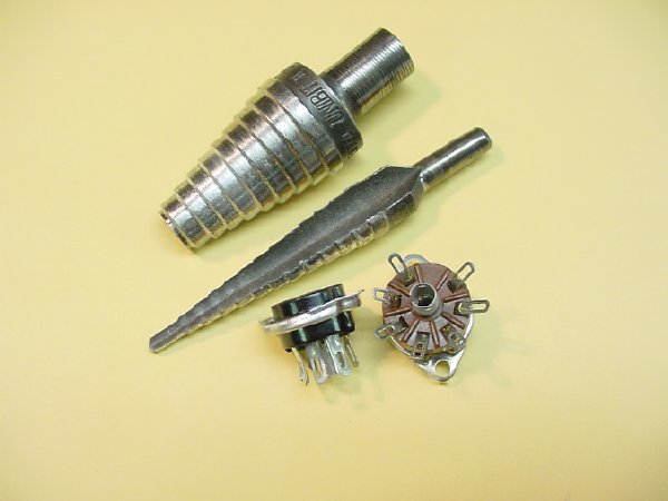 If
you don't have a "Unibit" to drill holes you might try and find
one,it makes a nice neat hole and you just keep drilling until the socket
fits. If you drill too far you wind up with a very big hole but it will
still be neat.
If
you don't have a "Unibit" to drill holes you might try and find
one,it makes a nice neat hole and you just keep drilling until the socket
fits. If you drill too far you wind up with a very big hole but it will
still be neat.
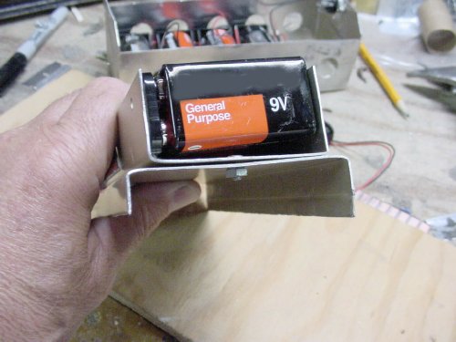 When
you fabricate the "9 volt tray" you want a tight fit so that the
9 volt batteries (total of 10) will remain in place. You will not
need any 9 volt battery holders. Don't forget to put the connector on the
9 volt batteries when doing your trial fitting. The rear cover for the radio
will cover the top of the tray and keep the batteries in place.
When
you fabricate the "9 volt tray" you want a tight fit so that the
9 volt batteries (total of 10) will remain in place. You will not
need any 9 volt battery holders. Don't forget to put the connector on the
9 volt batteries when doing your trial fitting. The rear cover for the radio
will cover the top of the tray and keep the batteries in place. 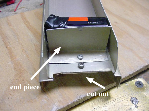 This
is the top of the "straddle tray" , the cut out section allows
for wire connections to pass through the tray to the bottom distribution
board. The top U shaped "9 volt tray" has
a small end piece configured to keep the 9 volt batteries from from sliding
forward out of the tray during maneuvers at the hamfest such as dropping
the radio while in the hamburger line.
This
is the top of the "straddle tray" , the cut out section allows
for wire connections to pass through the tray to the bottom distribution
board. The top U shaped "9 volt tray" has
a small end piece configured to keep the 9 volt batteries from from sliding
forward out of the tray during maneuvers at the hamfest such as dropping
the radio while in the hamburger line. 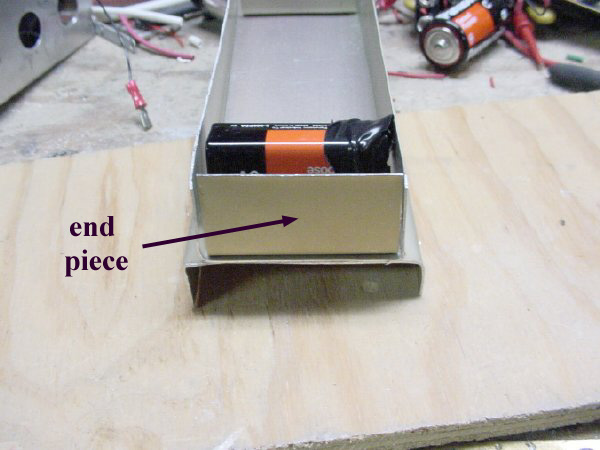 The
"9 volt" tray also has a small piece of aluminum fabricated as
a end piece at the bottom of the tray for the same reasons as given before
but you can include the hot-dog line.
The
"9 volt" tray also has a small piece of aluminum fabricated as
a end piece at the bottom of the tray for the same reasons as given before
but you can include the hot-dog line. 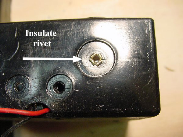
 There
is space between the ends of the 1.5 volt battery holders and the sides
of the main tray but I would insulate the rivets on the side of the battery
holders anyway.
There
is space between the ends of the 1.5 volt battery holders and the sides
of the main tray but I would insulate the rivets on the side of the battery
holders anyway.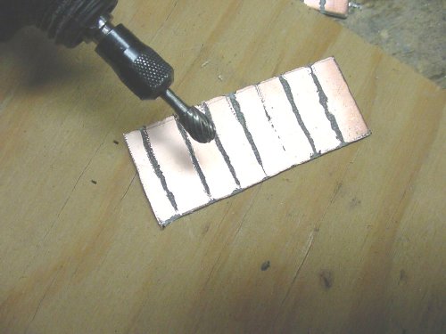 I
fabricated a distribution board for the wiring. The Dremel Tool comes in
handy for creating wiring pads to organize your wiring.
I
fabricated a distribution board for the wiring. The Dremel Tool comes in
handy for creating wiring pads to organize your wiring. .JPG) I provided extra pads on the board for future expansion. What
expansion? How about a tone board for 150 cycles.
I provided extra pads on the board for future expansion. What
expansion? How about a tone board for 150 cycles. There
is plenty of room at the top of the tray for the main 7 pin connector and
the connector wiring.
There
is plenty of room at the top of the tray for the main 7 pin connector and
the connector wiring. 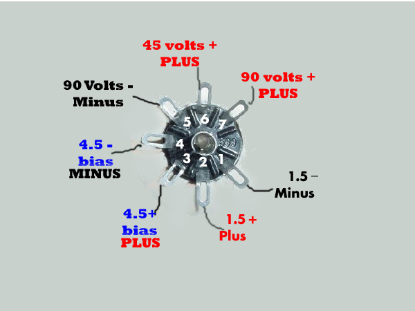
 Looking at the "bottom" of the tube socket, the pin numbers are
shown.
Looking at the "bottom" of the tube socket, the pin numbers are
shown. 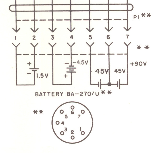
Actual wiring diagram taken from the manual
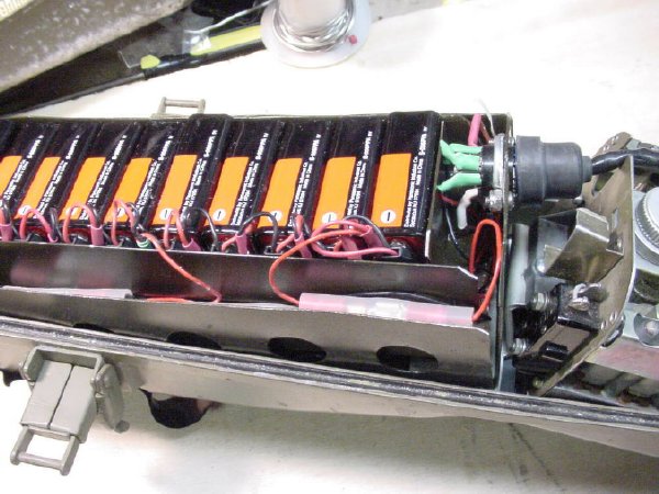
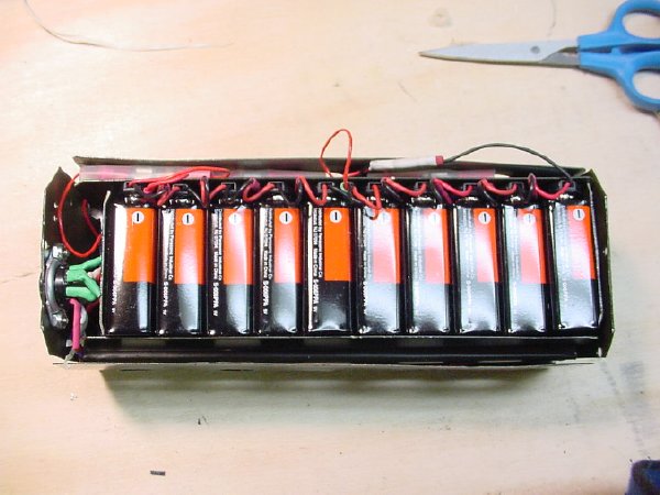
 The 9 volt wiring harness with the connectors in series. Notice the
tap for 45 volts on the string of connectors. An additional lead was soldered
on each end for the spade connectors and it was covered and reinforced with
heat shrink.
The 9 volt wiring harness with the connectors in series. Notice the
tap for 45 volts on the string of connectors. An additional lead was soldered
on each end for the spade connectors and it was covered and reinforced with
heat shrink. 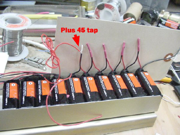 Install a tap for the 45 volts. Insulate connections with
heat shrink**
Install a tap for the 45 volts. Insulate connections with
heat shrink**
** Therapist for heat.
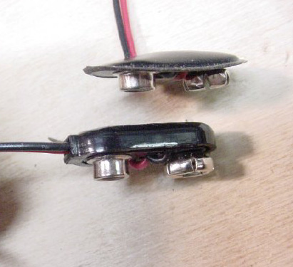 Their
are many styles of 9 volt battery connectors , I prefer the more rugged
type, buy em at the hamfest or its Rad Shack part number 270-324(package
contains 5 connectors ), very nice rugged connector.
Their
are many styles of 9 volt battery connectors , I prefer the more rugged
type, buy em at the hamfest or its Rad Shack part number 270-324(package
contains 5 connectors ), very nice rugged connector.  Common
spade connectors are used for connections between the 9 volt battery removable
tray and the distribution board. If you don't have a real crimper tool,
get one while you are Rad Shack.
Common
spade connectors are used for connections between the 9 volt battery removable
tray and the distribution board. If you don't have a real crimper tool,
get one while you are Rad Shack.
The spade lugs help you disconnect the 9 volt tray for service. Or if you don't want to bother then just use long leads.
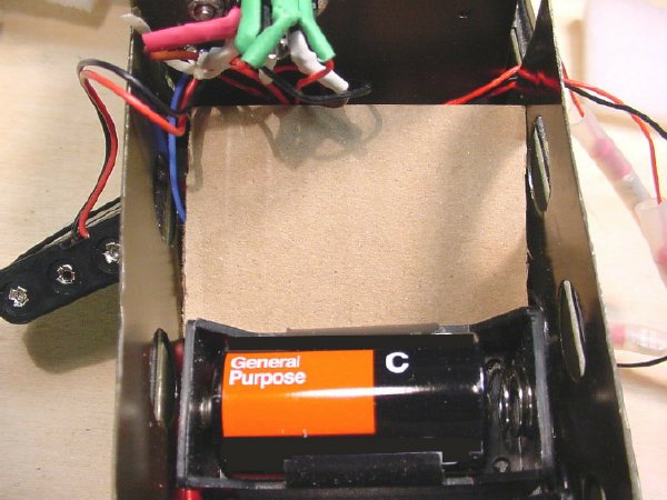
 Cover
the "distribution board" with a piece of cardboard and lay the
AAA Bias pack on top. Hide the emergency hamfest money under the card board.
Cover
the "distribution board" with a piece of cardboard and lay the
AAA Bias pack on top. Hide the emergency hamfest money under the card board.

Spade lugs are covered with clear insulation.
 I
love the smell of zink chromate
in the morning.
I
love the smell of zink chromate
in the morning.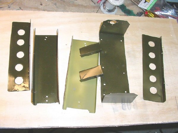 Finish the project with a coat of Olive Drab.
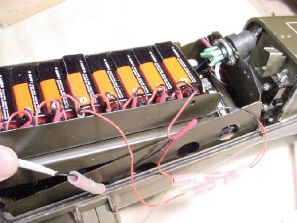 The upper tray slides into the lower tray to straddle the C
cell packs.
The upper tray slides into the lower tray to straddle the C
cell packs. 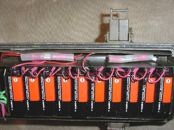 The
spade connectors stow in the sides between the "9 volt tray" and
the main tray.
The
spade connectors stow in the sides between the "9 volt tray" and
the main tray. 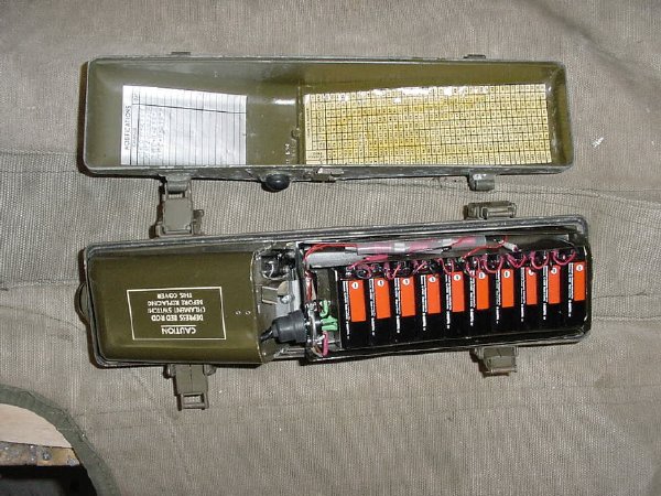 When you put on the rear cover it will hold the entire assembly in place
and the 9 volt batteries will not go any where.
When you put on the rear cover it will hold the entire assembly in place
and the 9 volt batteries will not go any where. 
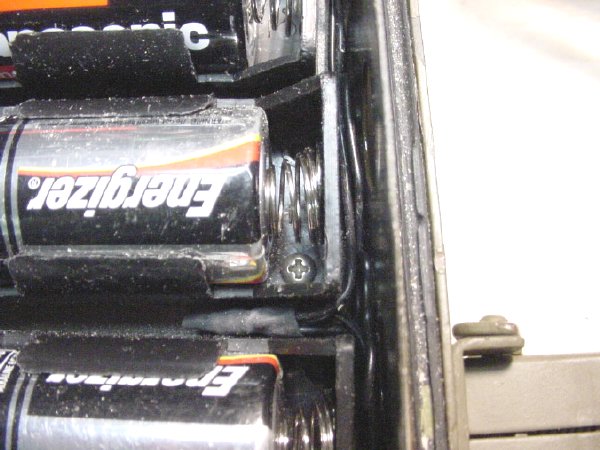
Here is a nice shot of the interior with the cover on, as you can see the entire battery assembly fits perfectly.
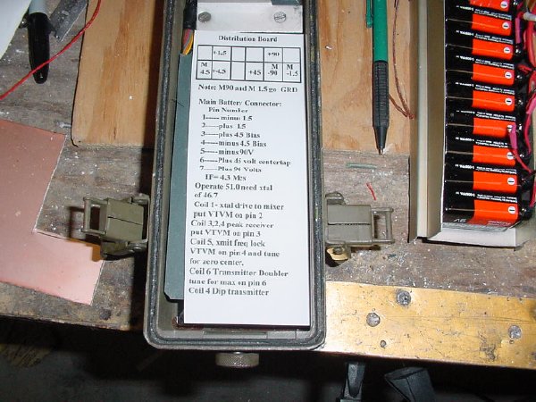
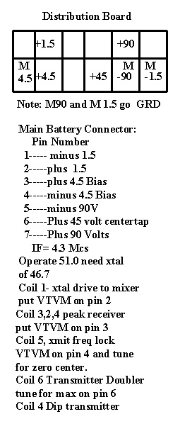 A
Secret placard was placed into the radio under the battery box on top of
the radio battery card. Contains vital information for the radio and
the distribution board. (Right click on the chart picture
and print)
A
Secret placard was placed into the radio under the battery box on top of
the radio battery card. Contains vital information for the radio and
the distribution board. (Right click on the chart picture
and print)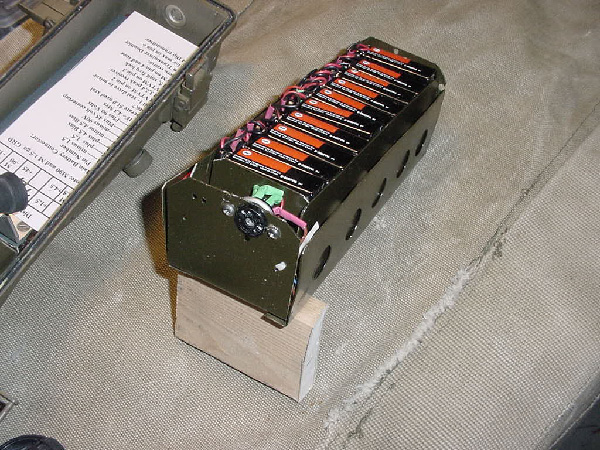
Tray ready for insertion.
 Note that there is plenty of room for the main tray 7 pin
connector and you can hide a P-38* in there if you want.
Note that there is plenty of room for the main tray 7 pin
connector and you can hide a P-38* in there if you want.
*thing u open da lima bean rations with
 Nice fit and plenty of room. Ready for the MRCA Military Radio Meet or the
"Cold War Net" at Dayton.
Nice fit and plenty of room. Ready for the MRCA Military Radio Meet or the
"Cold War Net" at Dayton.