Mission: Provide variable frequency control for the PRC-47
Revised 9-24
Lots of folks have accomplished this simple modification.
This modification was first published in 2003 but had an error in resistors selected and this error was caught by IKK4YNG, Paolo and also Jim KF7A was involved because he discovered that the could reverse bias the original modification and get a plus or minus swing. That should have been my clue that I had selected the wrong resistor on the wrong side of the varicap. Anyway the modification worked fine but this new revision is better and and the good news is I discovered that you could obtain a better frequency swing by reducing the shunt capacitor on the varicap.On the radios that I have made this modification the swing was sufficient for the new channels on 60 meters. I have never made any mistakes in the past with any of my modifications and this is the first well maybe not quite the first.
Overview: A simple mod requiring one 100K pot and 20 inches of wire. Anyone can accomplish this mod that has a soldering iron. The on board regulated power supply is utilized for the voltage.
 Your
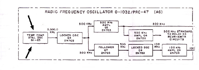
target is the Master Oscillator . This oscillator feeds the entire frequency
chain.
Your
target is the Master Oscillator . This oscillator feeds the entire frequency
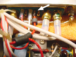
chain. 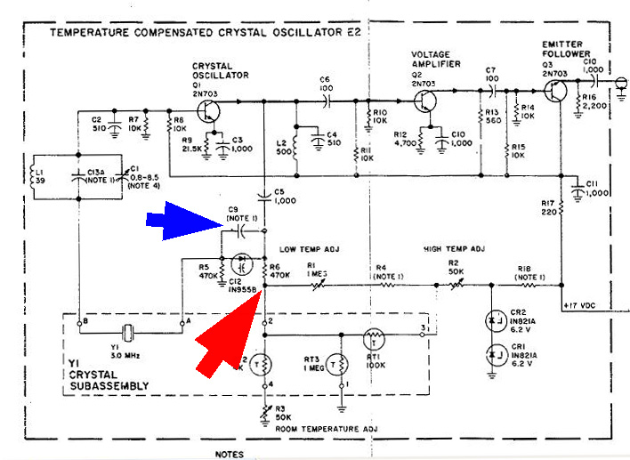 CLICK to Enlarge. The
mod consists of small reversible changes in the circuit of the R.F. Oscillator
module. All you have to do is to lift and disconnect the
end of a resistor R-6 (RED ARROW)
and solder on a wire to the lifted end of R-6, and if necessary lift the
end of a small cap C-9 (Blue Arrow) in the Oscillator module. By lifting
the resistor and disconnecting it from the temperature compensating network
of the module you will then be able to provide a voltage via a 100K Potentiometer
mounted on the front panel of the radio to R-6 in order to swing C-12
a diode varicap. The voltage for the potentiometer will come from the
set's internal regulated supply. Yes you are disconnecting the temperature
compensation circuit but unless you are going to operate in extreme climates
I don't think you will need it.
CLICK to Enlarge. The
mod consists of small reversible changes in the circuit of the R.F. Oscillator
module. All you have to do is to lift and disconnect the
end of a resistor R-6 (RED ARROW)
and solder on a wire to the lifted end of R-6, and if necessary lift the
end of a small cap C-9 (Blue Arrow) in the Oscillator module. By lifting
the resistor and disconnecting it from the temperature compensating network
of the module you will then be able to provide a voltage via a 100K Potentiometer
mounted on the front panel of the radio to R-6 in order to swing C-12
a diode varicap. The voltage for the potentiometer will come from the
set's internal regulated supply. Yes you are disconnecting the temperature
compensation circuit but unless you are going to operate in extreme climates
I don't think you will need it.
By lifting one end of C-9, which is in paralleled with the varicap you are effectively removing it from the circuit and thus increasing the operating value of varicap C-12 making its capacitance higher and more effective.
Note: Some sets do not have C-9, other sets had 2 or 3 capacitor's in parallel as C-9 as determined at the factory. C-9 is composed of a single or several brown micas.
Note: As a suggestion I would do the R-6 mod first, test the unit and note the frequency swing and if more swing is needed then lift the end of C-9(s)
Stay with me, this is a simple modification I promise.
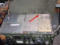
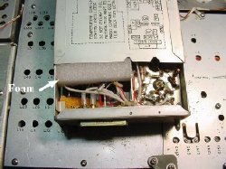
Target Module, last one in the right rear. Marking on the top is Oscillator R.F.
Unscrew the module retaining screws from the bottom of the radio, remove the module and then remove the module cover, the cover slides off.
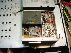
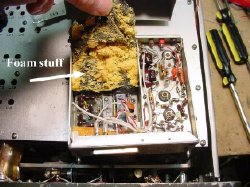 Take
out the foam. Be sure and remove foam from the correct side. This is the
right side.
Take
out the foam. Be sure and remove foam from the correct side. This is the
right side.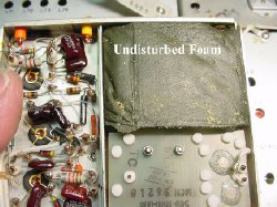 THIS
IS THE WRONG SIDE
THIS
IS THE WRONG SIDE 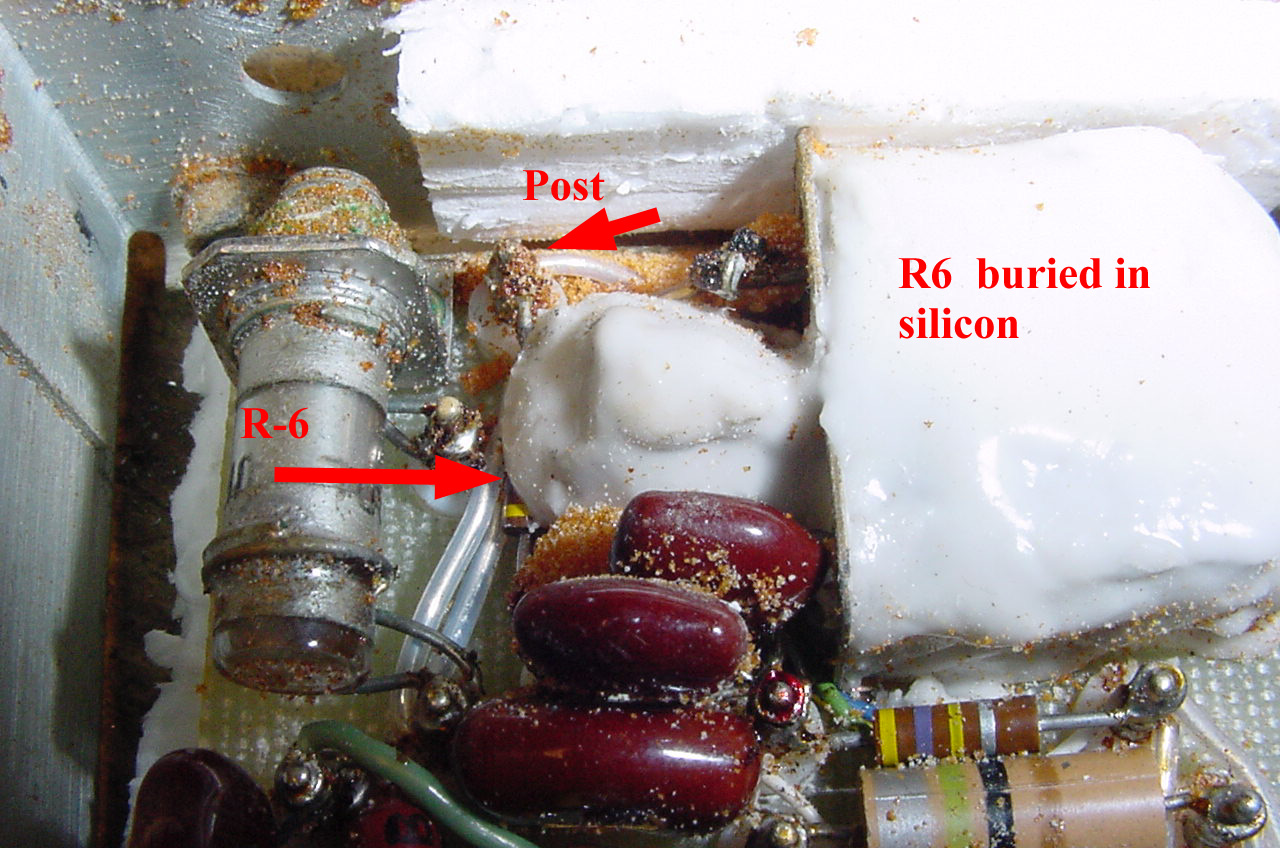 The
first target R-6 (Red Arrow) a 470K resistor.(Yellow violet yellow) going
to connection post near the top of the module.You need to lift the post
end of R-6 free of the post. In the photo the post is marked by a RED
ARROW. Notice that on this particular set that the body of R6 was
buried in silicon. IMPORTANT: When you lift
the end of R-6 from the post do not remove any other wires on this post.
You may have to cut away a portion of the silicon covering R-6.
The
first target R-6 (Red Arrow) a 470K resistor.(Yellow violet yellow) going
to connection post near the top of the module.You need to lift the post
end of R-6 free of the post. In the photo the post is marked by a RED
ARROW. Notice that on this particular set that the body of R6 was
buried in silicon. IMPORTANT: When you lift
the end of R-6 from the post do not remove any other wires on this post.
You may have to cut away a portion of the silicon covering R-6. 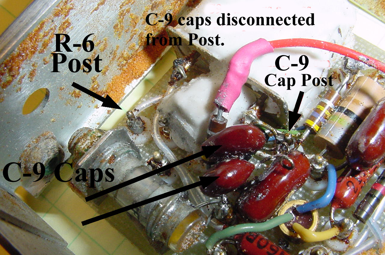 Click
to enlarge. Unsolder and lift the end of
R-6 clear of the post (tie point) and connect a short piece of wire to
the freed end of R-6. This wire run to the bottom of the module for connection
to an unused pin. In the photo R-6 is shown with a red wire attached.
Click
to enlarge. Unsolder and lift the end of
R-6 clear of the post (tie point) and connect a short piece of wire to
the freed end of R-6. This wire run to the bottom of the module for connection
to an unused pin. In the photo R-6 is shown with a red wire attached.
Do not unsolder any other wires on the R-6 terminal post.
As a suggestion I would do the R-6 mod first, note the frequency swing and if more swing is needed then lift the end of C-9(s)
If Caps C-9 are in place on your set then lift the end or ends if multiple caps. Leave any other connections to any of the posts on the posts , do not remove them.
 THIS
IS A PICTURE OF THE CONNECTOR IN THE BOTTOM OF THE OSCILLATOR MODULE.
The oscillator module plugs into J-9 on the main chassis. You are going
to use a spare pin to supply the
variable voltage from a panel mounted pot fed through this module pin
to R-6
THIS
IS A PICTURE OF THE CONNECTOR IN THE BOTTOM OF THE OSCILLATOR MODULE.
The oscillator module plugs into J-9 on the main chassis. You are going
to use a spare pin to supply the
variable voltage from a panel mounted pot fed through this module pin
to R-6
Select a spare pin on the module connector and connect the new wire from the free end of R-6 to this pin. This way you will be able to provide a variable voltage to the module for frequency control and still be able to plug and unplug the module without any extra wires. I used pin 4, its a nice even number and easy to get to.
I used some type 77 ferrite beads to de-couple the wire but ran tests without the beads, but for best construction practices I highly recommend using the beads.
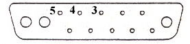
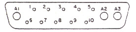 Diagram
of the module connector located in the bottom
of the module, Pin 4 is between pin 3 and pin
5.
Diagram
of the module connector located in the bottom
of the module, Pin 4 is between pin 3 and pin
5..jpg) This
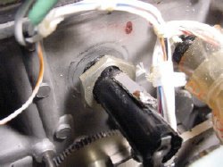
is a shot of J9 underneath the chassis showing
the spare pins available. I choose pin four, the second pin over from the
large connectors A2 and A3. In this picture my voltage control wire(white
arrow)has all ready been connected. This picture is for information only
you will connect the pin later.
This
is a shot of J9 underneath the chassis showing
the spare pins available. I choose pin four, the second pin over from the
large connectors A2 and A3. In this picture my voltage control wire(white
arrow)has all ready been connected. This picture is for information only
you will connect the pin later.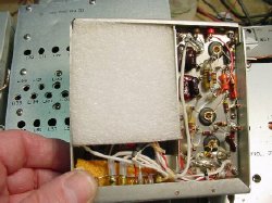
Replace the foam with a new piece.
Replace cover, trim foam as necessary.
 Remove
the 115 volt fuse holder(originally suggested by Dennis Starks), this
will create a hole, the hole will be used for mounting the frequency control
pot.
Remove
the 115 volt fuse holder(originally suggested by Dennis Starks), this
will create a hole, the hole will be used for mounting the frequency control
pot.
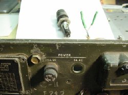
Heat shrink the unsoldered leads and
secure with a cable tie.
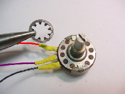 Connect
3 wires to the pot. Use a lock washer to keep the pot from moving once it
is installed. I used a 100 K pot but 50K , 250K will work, play with it.
Connect
3 wires to the pot. Use a lock washer to keep the pot from moving once it
is installed. I used a 100 K pot but 50K , 250K will work, play with it.
A handy shop tool is an extra hand.
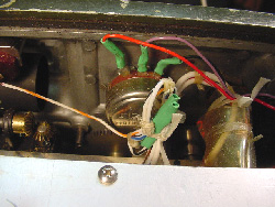 In
this picture of the rear of the pot mounted in the hole, Violet
the center tap supplies the variable voltage to pin 4 of J9(Osc module
socket), the left red wire will go to the 20 volt voltage source and the
far right wire (black) is grounded to the chassis.
In
this picture of the rear of the pot mounted in the hole, Violet
the center tap supplies the variable voltage to pin 4 of J9(Osc module
socket), the left red wire will go to the 20 volt voltage source and the
far right wire (black) is grounded to the chassis. 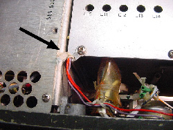 A
small solder lug is used for the ground wire
of the pot and as a strain relief the other wires.
A
small solder lug is used for the ground wire
of the pot and as a strain relief the other wires.
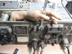
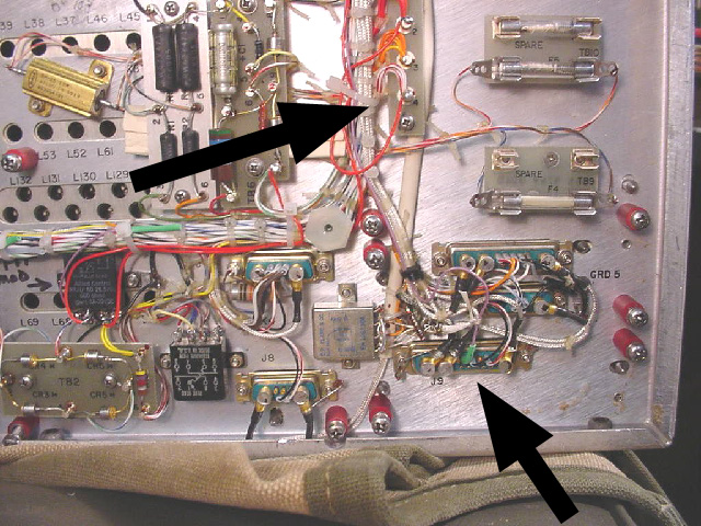 Next target areas. Top arrow points to the voltage distribution strip. The
bottom arrow points to J-9 the oscillator chassis socket.
Next target areas. Top arrow points to the voltage distribution strip. The
bottom arrow points to J-9 the oscillator chassis socket. 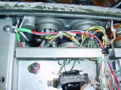 Snake
the wires from the pot down and behind the front panel, secure with a solder
lug and cord or cable tie, and then run through the chassis grommet.
Snake
the wires from the pot down and behind the front panel, secure with a solder
lug and cord or cable tie, and then run through the chassis grommet. 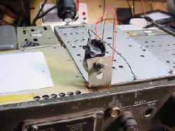 My
test jig that sat on my bench for a month. Amazingly stable. Really neat
installation which is typical of my work.
My
test jig that sat on my bench for a month. Amazingly stable. Really neat
installation which is typical of my work. 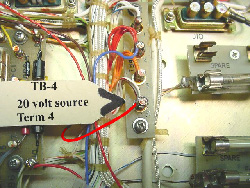 Connect
the RED end wire of the pot that you installed
to terminal 4 of TB-4,this point is going to supply regulated 20 volts DC
from the radio's power supply. The bottom of the picture is the rear of
the radio. On some radios TB-4 was not marked on the chassis.
Connect
the RED end wire of the pot that you installed
to terminal 4 of TB-4,this point is going to supply regulated 20 volts DC
from the radio's power supply. The bottom of the picture is the rear of
the radio. On some radios TB-4 was not marked on the chassis. 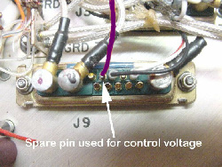
Connect the center wire of your pot to pin 4 of J-9.
 Pin
4 is next to pin 3. Pin 3 is next to pin 2. Pin
2 is next to pin 1.
Pin
4 is next to pin 3. Pin 3 is next to pin 2. Pin
2 is next to pin 1. 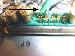 Put
a piece of heat shrink on the wire. Its usually easier to put the heat shrink
on the wire first and then solder the wire.
Put
a piece of heat shrink on the wire. Its usually easier to put the heat shrink
on the wire first and then solder the wire.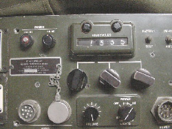
The knob is installed. To check calibration and find the 12 o'clock or center position for your pot tune in a time standard, I like NY VOLMET on 3.485 and 6.604 which is constant USB voice. Also you can tune in CHU on 7.335.
RETURN to K4CHE Index
For information on ferrite beads see: