
Info On: 24-12 Voltage converters, Vehicle starting and stopping precautions, using the KY-65 mount for the PRC-77 and other electrical tips.
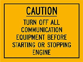
The best protection is to turn all comm gear off
prior to starting and stopping the engine.
Remember that when stopping
the engine the alternator is suddenly taken off line and again
this is rapid shedding of the inductive load and a spike is produced.
More details later on this page.
A tempting solution for 12 volt power is to just tap on one of the 12 volt batteries. Best advice is don't do it. But when using just one battery be sure and choose the battery that has the negative terminal direct to vehicle chassis ground. Do not use the high battery which would allow above ground operations and might potentially place the chassis of your 12 volt device at a dangerous potential.
BTW those "Magic" battery terminal protectors which are chemical pads from AutoZone and Walmart really help with the corrosion. They are impregnated with some sort of secret chemical. In the past we used Baking Soda but the modern pads do work.
Use a single terminal point for all vehicle and radio connections- - try to stay away from using one of the battery clamps as a tie point for numerous cables. On longer runs for best noise reduction install a separate ground cable. "Welding cable" can be found in some pretty large sizes and provides a very low loss cable for power. Google "Welding Cable". Connected above are the vehicle electrical, battery, the slave connector, and the radio buss.
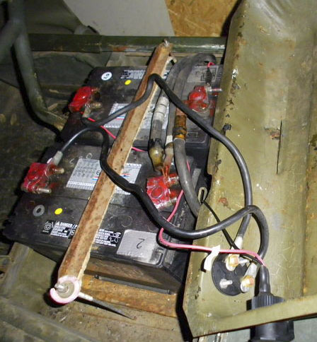
Don't do this!
Fact: When starting your vehicle the voltage varies considerably and voltage spikes are created when the starter is released and the inductive load is instantly shedded. Often these voltage spikes exceed many times the battery voltage.
Radio Survival Tip: Turn off all radio equipment when starting or stopping your vehicle engine. This is a good procedure for your M151A1 and don't forget to follow the same procedure for your 12 volt civilian vehicle that has that Japanese Rice box installed.
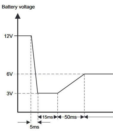
Texas Instruments Chart (portion)
During start the battery voltage varies considerably. In the example above a 12 volt battery drops down to approx 3 volts during a "cold" start. The inrush current on the starter is very high in the hundreds of amps. But it is not the current that creates the problem it is the inductive load.

Texas Instruments Chart
Typical "inductive spikes produced by rapid load shedding during starting are pretty short in duration but the voltage "spike" is very high when compared to the battery voltage. Typical estimated spike values that I have used in the past have been to just multiply the battery voltage by 3 which in the case of a 24 volt battery would be over 70 volts. However Texas Instruments has a document indicating higher values.
More information as well as protective measures can be found at Texas Instruments.
http://www.ti.com/lit/an/snva681a/snva681a.pdf
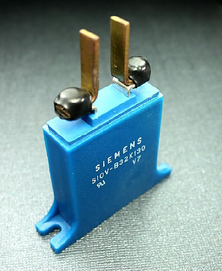
You can get creative and install devices such as metal-oxide varistors (MOVs) but selecting the proper voltage and current rating can be a problem and getting a device to survive numerous "hits" can be a challenge. The best protection is:
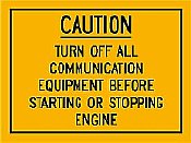 The
best protection is to turn all comm gear off prior to starting and stopping
the engine.
 Remember that when stopping the engine the alternator is suddenly taken off line and again this is rapid shedding of the inductive load and a spike is produced.
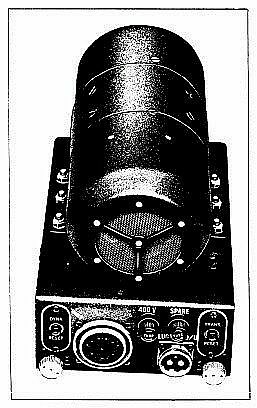
Another Starting Tip: When powering up a ART-13 or similar dynamotor in your Operations Center - Turn off any sensitive or solid state equipment that is also power by that buss including that cute little Chinese LED voltage display that you purchased on ePay. This is not instant load shedding but the voltage variations on the buss are high. BTW if you are using batteries inside your quarters for this high current device - my advice is don't. Batteries belong in a well ventilated vehicle not inside your home.
K4CHE
REMEMBER Turn off all comm gear prior to start or stopping the engine.
- - - - - - - - - - - - - - - - - - - - - - - - - - - - -
KY-65 Used with the PRC-77
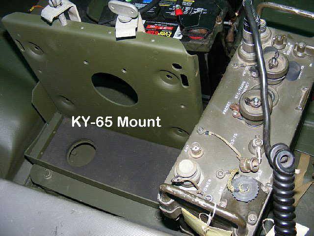
Mounting
the PRC-77 in a mobile mount is much better than just sitting it on the
floor. The KY-65 mount can be pressesd into service. However for extended
operations a 12 volt power source becomes necessary and reliance on batteries
is not part of the ops plan. BTW this particular PRC-77 has been modified
for "noise" squelch and more info on noise squelch will be posted.
Standard shock mounts came with the KY-65 mount.
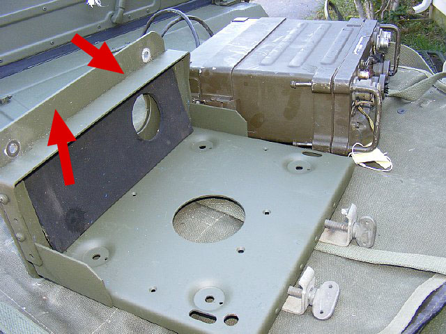
A
small mounting plate was fabricated and attached to the bottom to allow
vertical mounting. Note the hole for the power cable and connector and
in this case the cable for the U-383/VR
Now that I see more pics on your page, although it's set up for a KY-65
now - it looks as though it's one of the types that's adjustable at the
base end to allow mounting of a KY-38 instead by removing the two Phillips
screws on each side, raising the bar until the second set of screw holes
line up, then reinstalling the Phillips screws. These are around too,
and every one I've ever seen has been set up for the KY-65 rather than
the 38. There is a second non-adjustable version of this mount which is
KY-65 only...usually the type fitted to GRC-206 FAC-racks.
K4CHE
The PRC-77 mounted vertically gives the driver easy access to controls. Note the Cockpit Utility Light in the upper left corner - very popular on USAF Forward Air Controller vehicles.
The U-383/VR can be used to power the PRC-77 during mobile or fixed operations. The supply is the same size as the CY-2562 battery box and uses the same mounting system.
The U-383/VR technology is a little outdated but the supply that I have is very rugged and has survived. Power in Vs power out efficiency? Not very good and is approximately 60 percent. A active voltage regulator circuit is not but do not expect precise voltage regulation- expect voltage variations between 12 to 15 plus or minus. It is tempting to install a couple of externals terminals on the case for external 12 volt power to other devices but I have not made this mod and prefer a different 24-12 converter which is shown later on this page.
K4CHE
PRC-77/U-388 combo on the hood. The modified NATO slave adapter on the left provides a convenient 24 volt connection.
-
- - - - - - - - - - - - - - - - - - - - - - - - - - - - - - -
Modify a NATO adapter to a K4CHE Slave Terminal Connector
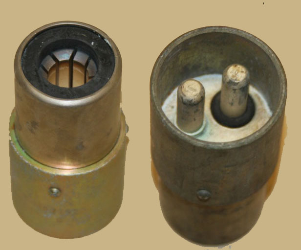
A
NATO slave adapter can be modified for terminals. A length of copper pipe
is inserted in the center for a positive contact. The case of the adapter
is at ground potential.
Terminals were added for easy connections to radios in the field.
Use 1/2 inch copper pipe inserted into the center for the positive connection. Short lengths of pipe are available at the usual home supply stores in the plumbing section.
The
copper pipe is used for Positive + contact. A small bracket
mounted on the side is the ground.
- - - - - - - - - - - - - - - - - - - - - - - - - - -
- - - - - - - - - - - - - - - -
This
24-12 converter is very efficient and bench checks have show it at approximately
80-85 percent. Use it to power your "civilian" devices or even
your PRC-77. This one was acquired at "Aberdeen" for a bargain
price. On Epay search for 24-12 converters. This particular model has
a common ground with the vehicle electrical system - - - in other words
the input negative and output negative terminals are tied.
- - - - - - - - - - - - - - - - - - - - - - - - - - - - - - - - - - - - - - - - - -
Main Radio Buss Wiring
The
24-12 converter does not take up very much room in the M151A1 tool storage
area which is located under the right seat. Shown above are the 24 and
12 volt distribution fuse boxes as well as a 50 amp contractor controlled
by a remote " Radio Master Switch".
NOTE: Both
24 volt and 12 volt battery "INPUT" lines are fused.
Each GE Fuse Block open and provides a convenient tie point for each voltage buss. The cartridge fuse is held by the top cover and when placed back on the block the fuse is inserted into the clamps. Easy on - easy off.
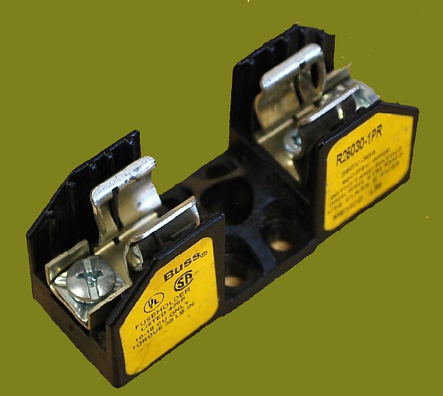
I
prefer a cartridge fuse and holder for high amperage DC lines. Shown above
is a sample of a typical cartridge fuse holder that is available.
I do not like to run 24 volt power cables for radio equipment without having a fuse at the beginning near the battery tie point.

The cartridge fuses are available at any home supply store. Time delay fuses are also available for high current surge conditions.
Throw that vinyl tape away an use rubber splicing tape for waterproof and rugged connections. It can be used on antenna connectors as well and is "removable". Purchase at your home supply store.
Plenty of room left inside the tool box for the standard M151A1 tool kit which includes the jack. Note the Master Radio Switch mounted on the lid.

The
newer inverter shown on the lower right is much smaller that my older
Astron that has served me well for all most 20 years and will be retired.
The larger Astron took up a lot of space in the tool area.
Astron still makes DC to DC converters.
Don't forget to make up a cigar lighter cable for your external 12 volt devices.

I
use a single RED guarded "Radio Switch" installed under the
right seat to control the Master Radio Buss via the 50 amp contactor.
Before starting and stopping it is easy to determine if every piece of
comm equipment is OFF and best of all when securing operations one switch
OFF prevents a dead battery.