
KWM-2A 60 Meter Ops
A
discussion of 60 Meters Operations using the KWM-2/2A with frequency control
by crystal or DDS VFO.
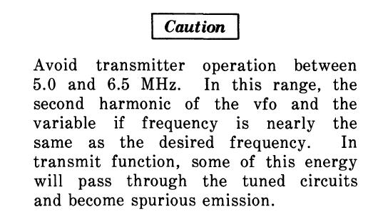
My testing goal was to confirm that the spurious emissions stated above actually occur on the narrow 60 meters segment. Keeping in mind that the 60 meter channels are just slightly inside the 5.0 to 6.5 Kcs segment mentioned in the published Caution.

Obviously I was happy with the 60 meter spurious emission testing or I would not have publish these pages with the info. The slight intrusion into the "Caution" zone produced negligible by products on 60 meters with or without audio. Even the 2nd harmonic was over 40 dB down and even further when using an external antenna tuner.
CLICK
to enlarge
About
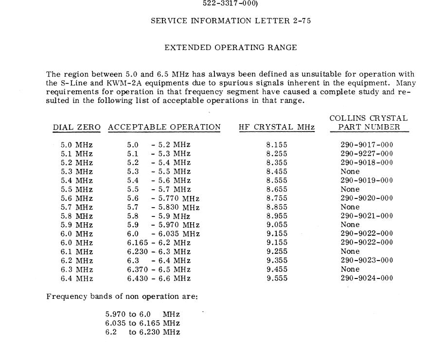
midway through my testing project I found the Collins Service Letter 2-75
dated October 1975 which backed up my results. The 60 Meter band channels
were not listed as a "non operation" frequency.
The
first test consisted of utilizing the 4.8 to 5.0 crystal (7.955 Kc) pulled
from the Collins CP-1 crystal pack and testing the KWM-2A on 5.0 Mc with
a dummy load. A quick check using a spectrum analyzer indicated
that the KWM-2A signal was clean at the upper edge of the 4.8 to 5.0 Mcs
span. A decision was made to continue testing on 60 meters in the 5.3
Mc range. Keeping in mind that the 60 meter channel segment was just slightly
inside the spurious emissions Caution range. However a method of Band
frequency control would be needed as the crystal pack did not contain
any crystals for 60 meters.
Operations on 60 meters covers a very small range in the 5 Mc band.
CLICK to enlarge
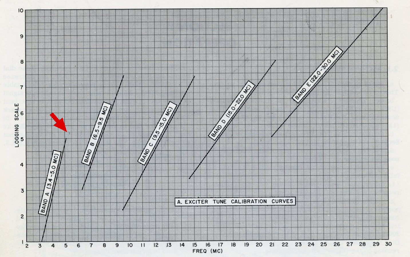
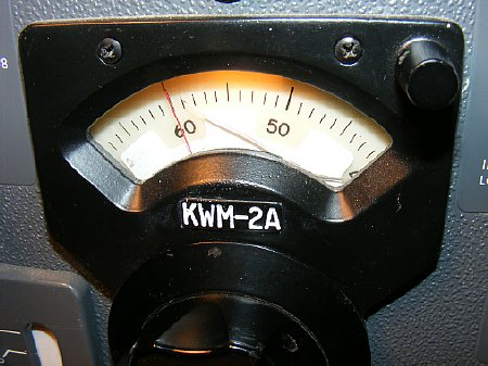
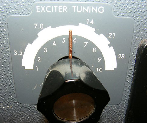
60 meters requires a slight intrusion into the "Caution Zone". By extending the logging scale graph lines a setting for the Tune control logging scale can be found and is between 5 and 6 on the scale. A similar chart can be found for the final PA.
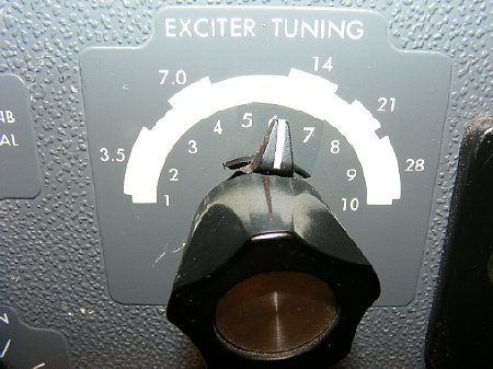
The logging scale on the Exciter Tuning and P.A. Tuning is numbered 1 to 10. The 60 meter tuning should fall between 5 and 6 on the scale.
CLICK
to enlarge
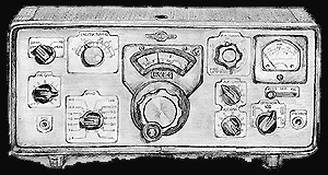
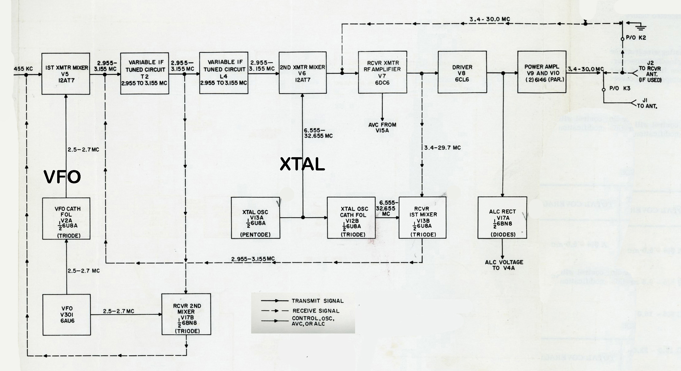
The
frequency scheme of the KWM-2 is dependent on the VFO (main tuning knob)
and the crystal deck (crystal mounting board) which uses HC-6 crystals.
On 75 meters a crystal of 6.955 is utilized to tune the band segment of
3.8 to 4.0 Mc.
.455 Mc + the VFO of 2.7 Mc = 3.155 Kc
Example:
The crystal of 6.955 is mixed with 3.155 to produce the bottom edge of
the tuning segment 3.8 to 4.0 Mcs. The VFO Knob is then tuned for the
coverage of 3.800 to 4.000 Kcs.
The
KWM-2 and KWM-2A band crystal formula is: "Lower edge of Desired
band + 3.155 Mc."
Example 3.800 + 3.155 = 6.955 (HC-6 crystal frequency)
NOTE:
For Bands above 12.0 Mc a different formula is used for the crystal calculation.
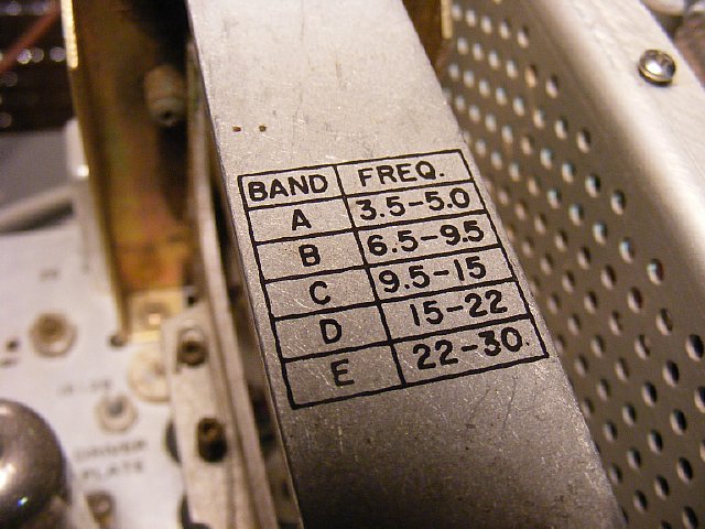
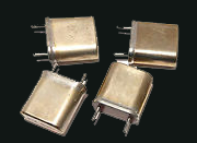
The band crystal sockets for the HC-6 crystals are frequency sensitive . Band A crystals are usually in the 6.5 to 7.9 Mc range to provide appropriate 200 Kc coverage for 3.5-5.0 Mc coverage. We will use a crystal or DDS VFO for the 60 meter band and place it in one of the Band A sockets. The other bands either do not work for 60 meters or when utilized provide very low drive.
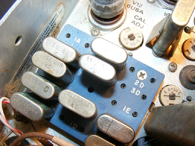
The HC-6 crystal deck is clearly marked. The A segment sockets ( 1A 2A and 3A)are the correct ones to use for 60 meters. Socket 1A located at the top rear is easy to access.

Socket 1A selection is at the very bottom of the Band Switch with the knob full CCW.
60
Meter Band Crystal Calculations.
The crystal formula
is: (Lower edge of Desired band + 3.155 Mc.) One possible solution would
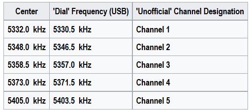
be to cover the 5.200 to 5.400 Mc range.
5.200
+ 3.155 = 8.355. To cover the 60 meter frequency of 5.357 (ch 3) with
this crystal the VFO dial would be set to 157 which is 157 Kcs from 5.200.
The crystal calibrator will be heard every 100 Kcs starting at the bottom
of the band on 5.200, in the middle of the band at 5.300 and at the top
of the band at 5.400.
Another
solution would be use a bottom band edge of 5.300.
5.300
+ 3.155 = 8.455
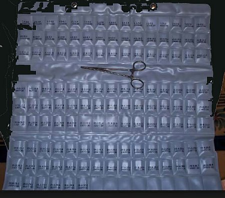
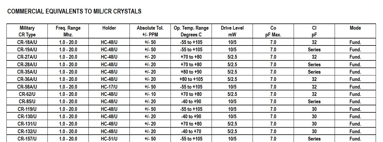
Crystal Specifications:
My
Collins CP-1 crystal pack crystals have CR-18 stamped on the side. I have
not actually ordered a crystal from International using this spec for
the KWM-2A but quote it here for information. Other CR-18 crystals that
were tested in the KWM-2 came out within a couple of hundred cycles. The
holder type is a HC-6 . The CR-18 specifications are shown in the graph.
CLICK
to enlarge

CLICK
to enlarge
Service
Letter 2-75 also listed the crystals as CR-18 and mentions ops below3.4
Mcs.

The dial calibration line can be moved about 12 Kcs or 6 Kc either side of center. A crystal that is a couple of Kcs off can easily be compensated by moving the line. Next I will discuss using " junk box" crystals.
Junk
Box Crystals
Look
in your junk box perhaps you have a crystal in a range that will cover
60 meters. For instance: A crystal marked 8.475 would cover from 5.320
to 5.520. However the dial will not be calibrated - - well not exactly.
Channel 3 the "MRCA" calling and net frequency of 5.357 would
be found on a dial setting of 37 or 37 Kcs up from zero. The crystal calibrator
100 Kc point would be found on 080. Confused yet?
Another
example: I found a crystal marked 8.505. This crystal will cover 8.505
- 3.155 = 5.350 which will be the bottom edge where the dial reads zero.
5.357 channel 3 would be found using this
crystal on a dial setting of 07 and a 100 Kc calibration point can be
found at 50 and 150 Kcs. Anyway look in your box perhaps you have a crystal
to play with.
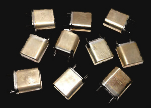
You can compare crystal activity of different crystals by using the Grid current - - more current = better crystal.
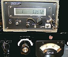
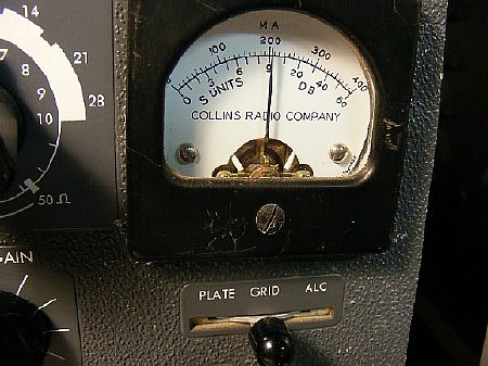
A rough check of frequency can be made with a small imported frequency counter. Don't get the counter antenna to close as you may burn out the front end. Since the KWM-2A uses a tone of approximately 1700 cycles to create a carrier in Tune and Lock positions your measurements with the counter in Tune or Lock will not represent the true center frequency of your SSB transmission. Best way to get on frequency is to listen to another station and adjust according. Let the KWM-2A warm up 30 minutes prior to operations.
Be sure and calibrate to the nearest 100 Kc point prior to ops. Notice the cracked dial, this set was rescued from the aluminum pile at Fitzgearld Salvage yard here in Chickenland and restored. Best guess is that it came from Dover AFB and was demilled prior to being sold as scrap.

A socket extender comes in handy when playing with different crystals. Use a HC-6 holder cut open and wired to a crystal socket with epoxy to hold it together.
The
tuning knob on my junk yard KWM-2 recovered from a local salvage yard
needs a pointer.
Be sure and peak the set on the correct band
as it is possible to peak the set on a different band.
Example: On 20 meters when tuning or peaking
the segment 14.0-14.2 it is possible to accidentally be tuned to a 11.7
segment that covers 11732.5 to 11932.5.
The tuning dial will be left of the 14 Mc point so that will be the clue.
Try it on receive.
Reason? The 14.0-14.2 band uses a crystal that is on 8577.5 and by tuning lower in frequeny the injection is switched.
8577.5
+ 3.155= 11732.5 Note the + sign.
My
junk yard KWM-2A recovered from a local scrap metal dealer. Needs a new
dial and Exciter tuning pointer and a cabinet.
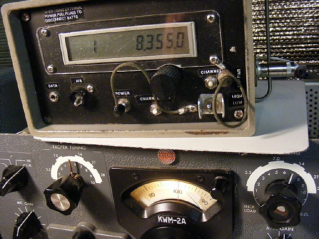
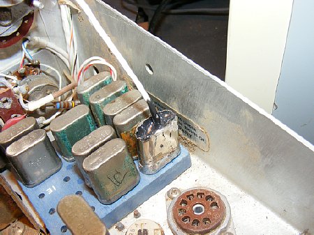
My DDS VFO came in handy to substitute for the
Band crystal by plugging into the 1A crystal socket. Shown above the frequency
of 8.355 provides a bottom band edge of 5.200 for coverage from 5.2 to
5.4 Mcs. The DDS VFO by its self does not provide enough voltage and is
around 250 mV but inside the DDS enclosure I have a 20 dB amplifier which
gives me a overall output of a couple of volts Peak to Peak. This was
enough to provide plenty of receiver sensitivity but grid current was
low and I was only able to get about 60 watts output on the transmitter.
I
use the N3ZI kit. The kit now comes with the surface mount IC soldered
to the board.
http://www.pongrance.com/dds.html
A
simple wide band amplifier kit can be found at:
http://www.kitsandparts.com/rfamp1.3.php
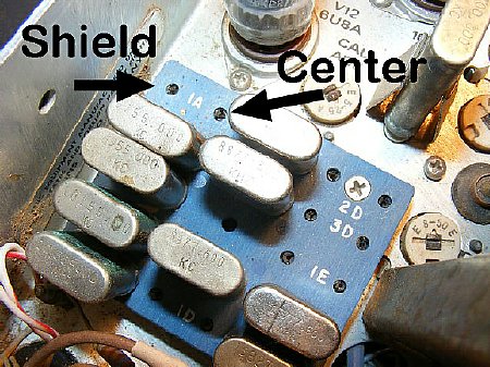
When connecting the DDS VFO to the crystal board socket use the outer pin for the shield. It will work either way. Play with it.
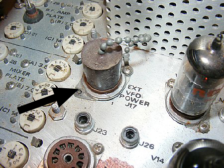
When using a "external" VFO for the 2500 to 2700 Kcs injection pull the plug from J17. The power will be removed from the main VFO(PTO) and the dial light will also go out as a reminder. The external VFO RF will be plugged in the rear of the set via a phono jack.

The external DDS VFO plugs into the EXT VFO phono jack on the rear of the set.
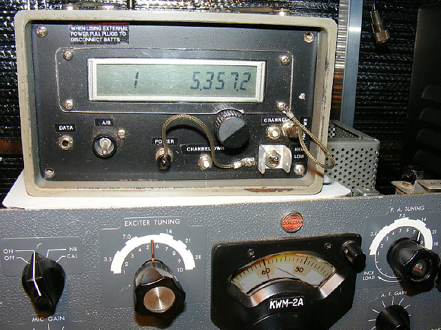
The DDS VFO can be used and the internal VFO turned off. Note that the KWM-2 VFO tuning scheme is 2500 Kc to 2700 Kc and as you tune the KWM-2A Knob higher in indicated frequency the actual KWM-2A VFO frequency is tuned lower starting at 2700 Kcs. Program your DDS VFO accordingly. Note that I have 5357.2 indicated on the DDS VFO so a slight frequency change will be required on the internal DDS IF frequency. It is possible to fine tune the DDS by different steps and you have the option of changing the display to indicate down to 1 cycle. The N3ZI manual is available on the web site.
My HC-6 socket
plug for the DDS VFO made from a HC-6 crystal housing.
Make your own crystal socket plug: Unsolder a HC-6 crystal
case housing, cut off the top. Connect miniature coax then
Resolder.
Fill with 5 min JB Weld epoxy. 20 minute project.
Q and A
Q. Can
you crystal control the VFO section of the KWM-2A?
A.
Yes you could try duplicating the circuit used on the Novice Adapter 399B-4
or 399B-5. Info below.
Q. What
crystals are used in the Novice Adapters?
A.
Crystals in the 2.500 Mc to 2.700 Mc range. The adapter actually replaces
the variable KWM-2 VFO. BTW the crystals for the 2500 2700 range are pretty
expensive.
Q.
Was the KWM-2 used on the U-2 aircraft?
A.
Don't know. Maybe. The KWM-1 was installed in many of the U-2s.
Usually in a pressurized container mounted just forward of the right wing.
A remote control head was mounted in the cockpit on the left side and
is shown in the now declassified Flight Manual (SECRET) dated 1 March
1959. Later if the KWM-2 was installed on the "Dragon Lady"
it would have probably used a similar crystal adapter as shown here. The
USAF used the KWM-2 in a variety of missions and a lot of time the radio
was placed it on the back seat of the M151A1 or placed on the hood when
doing remote airfield operations.
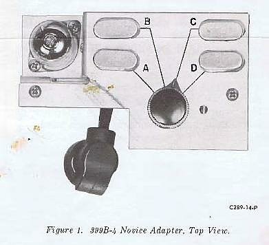
399B-4
Novice Adapter. Installed by removing the KWM-2 VFO tube and plugging
in this adapter in the vacant VFO tube socket. Then use the VFO tube in
the adapter. This adapter replaces the VFO section but the main Band Crystals
for the 200 Kc segments are still required.
Complete manuals
for the Adapters can be found on:
http://www.collinsradio.org/cca-collins-technical-archives/collins-radio-equipment-manuals/
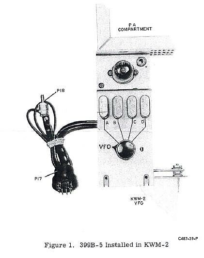
399B-5 is similar but the RF output plugs in the rear of the radio