The original tuning capacitor used by Mr. Crosby utilized a Miller 3 section (26 uuf per section) variable The original tuning capacitor had a part number of Miller 1461. Later on in the HBR series different Miller variable capacitor part numbers were used but they all were around 25 pF per section.
You are probably never going to find the original capacitor unless you find it on a "parts se"t at a hamfest or on eBay. But . . .
When you are visiting hamfests and eBay and looking for the tuning capacitor here are some suggestions. (Photos below)
a. Decide how you want the tuning shaft and sections configured, i.e. when looking at the front of the capacitor do you turn the shaft clockwise to make the capacitor decrease in value or do you turn it counter clockwise? Most builders prefer to turn the capacitor shaft clockwise and this rotates the plates and decreases the value thus raises the the frequency of the first oscillator and the frequency that the receiver is tuned to.
b . Choose a capacitor that can be firmly and easily mounted to the chassis.
c. Chose a capacitor that has a standard size shaft, usually 1/4 inch or be prepared to use adapters between your dial that you select and the variable capacitor.
d. As a general rule of thumb you are looking for a variable capacitor that has 3 or 4 plates per section.
e. As a general rule you are looking for a 3 section or a 2 section(see below) capacitor but if it has 4 or 5 sections you can probably use it depending on the length.
f. Look for older tube type FM(88 to 108) broadcast band receivers , they usually have an excellent tuning capacitor.
g. Older military VHF sets often have excellent capacitors . (But please don't destroy a good radio)
f. Look for ball bearings in the mount, look for good grounding of the shaft.
There are plenty of ways to solve the tuning capacitor problem.
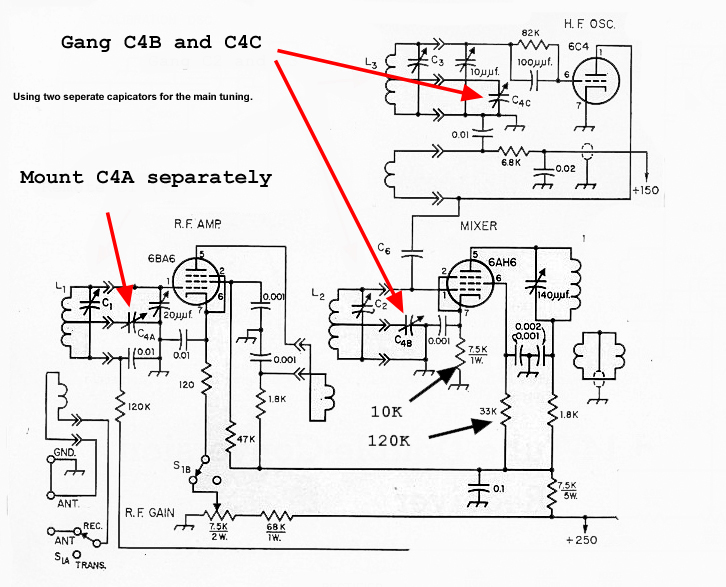
First of all you do not absolutely have to have a 3 section capacitor. You can just utilize a two section cap and use it for Mixer and HF Oscillator and then use a third variable capacitor and mount it near by and use that for the front end RF section. With a separate front end RF capacitor you will be peaking" the RF section as you make large excursion in frequency as you tune across the band very similar to the Preselector tuning on some of the older receivers. Look at the schematic there is also an 20 uuf "antenna trimmer capacitor that is in parallel with the first RF coil with a separate RF capacitor you can do away with the "antenna trimmer". Some builder prefer having a separate RF peaking capacitor as this makes the "tracking problems associated with the coils easier to resolve.
Click for schematic for RF, Mixer and HF Oscillator section.
All sections of the capacitor do not have to be the same. Granted this would be ideal but it is possible to work around this problem by varying the coil windings. Its not rocket science, you remove one turn from the coil section (RF, Oscillator, or Mixer when you have too much capacitance in that section of your variable or you add a turn when you do not have enough capacitance
Here are some photos of possible candidates:
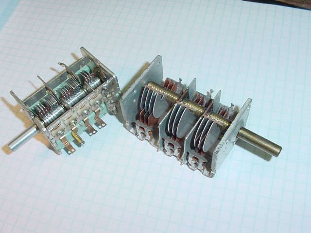
Here are two caps,
note that one or more of the plates may have to be removed and if desired
the cap on the left has an extra section that may have to be removed.
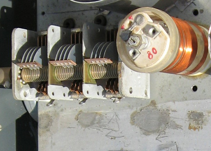
Note that as you turn the shaft clockwise plates emerge from the fixed
plates and the capacitance decreases.
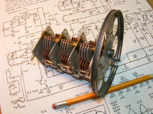
Here two variable's that are ganged together and a third will be mounted separately and will be used for the front end RF section as discussed above.

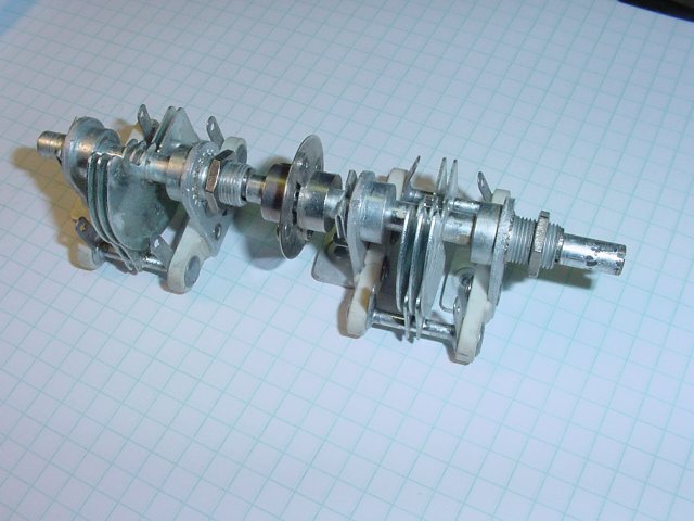
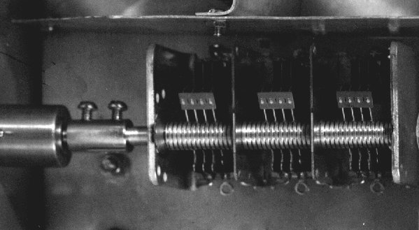
Here is a typical two section variable
removed from a military VHF set.
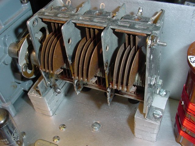
Here is a 4 plate capacitor
that had two much capacitance so adjustments were made on the coil windings
. Note the solid mounting technique, no vibration.
Found in a junk box at a hamfest for a buck. Probably used in a AM/FM broadcast band
receiver. Perfect.
 W2DGB
photo
W2DGB
photo Another 4 plate capacitor.
 W6TC photo
Capacitor used in the HBR-11