Testing each circuit immediately after you build it is an excellent way to arrive at a successful completion of your HBR project. I've included some testing ideas on these pages, sorry if it seems so disorganized but I wanted to show at least some photos of the testing process and to include some tips. There are several videos.
Build and test the receiver "backwards" - - - start with the audio section first, test it and get it fully functional and then you will be able to use it to test the other sections. Be sure and include the S- meter circuit as it will come in handy during testing and alignment.
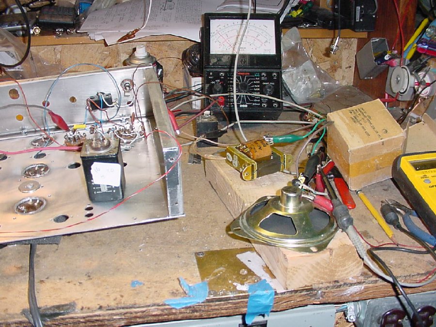
A rough indication of the frequency coverage of the first oscillator coil and your selected variable is easily accomplished using a Grid Dip Meter. Check that the frequency varies when you adjust the APC cap on top to be sure that the APC circuit is working properly.
I
highly recommend a very detailed testing of your first oscillator or VFO.
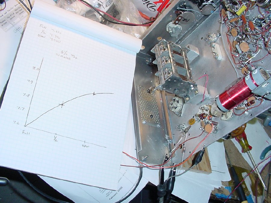
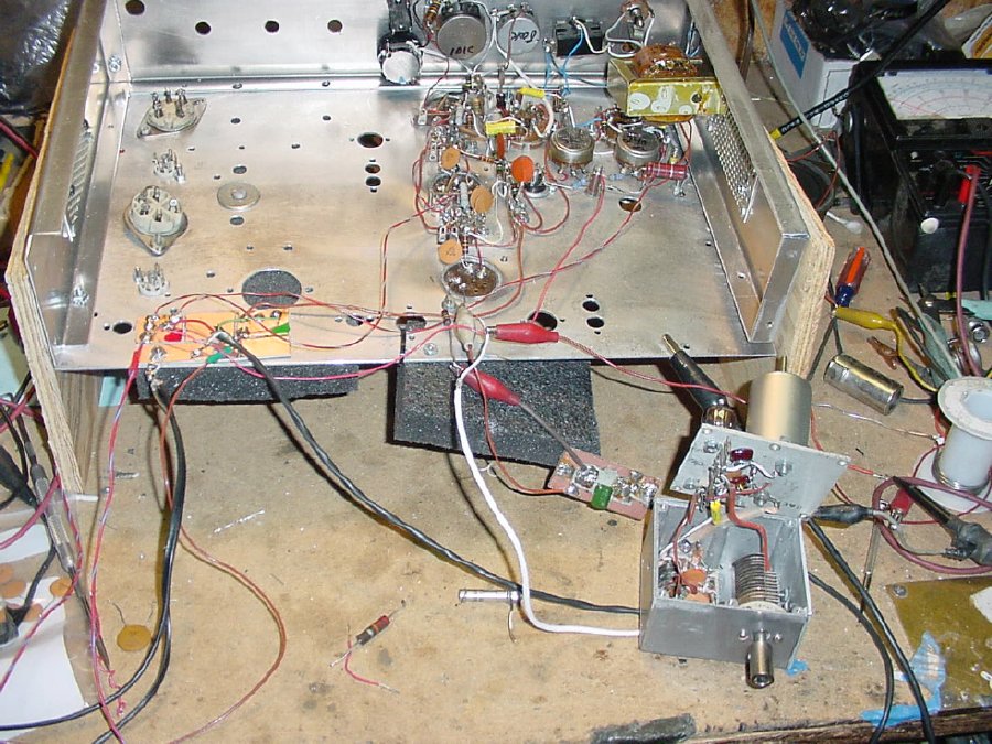
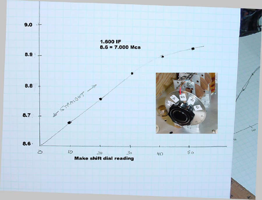
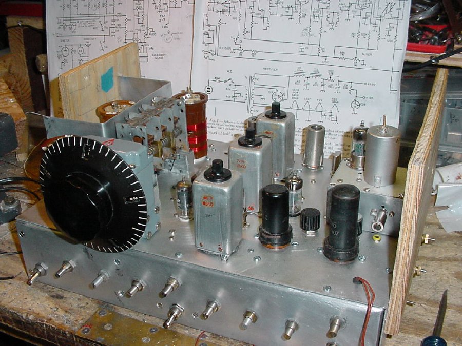
Notice that the 3 stage variable capacitor is mounted underneath the chassis
for initial testing. A rough frequency graph was accomplished just using
the position of the movable plates on the rotor as a reference. i.e.,
the plates were open 25 percent, 50 percent, 75 percent etc.
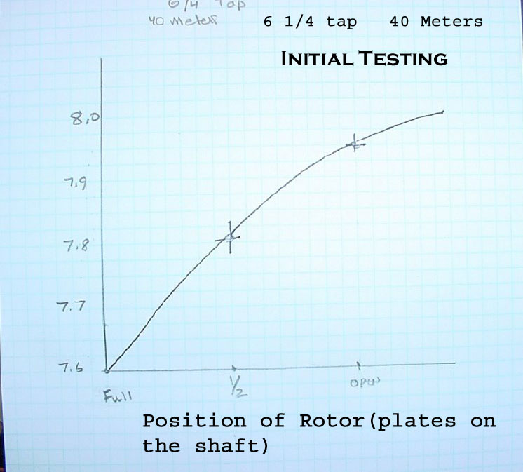
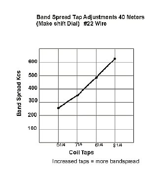
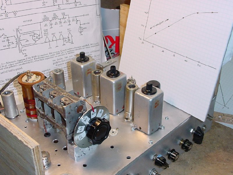
Shown
above is one of my first Oscillator graphs, note that I used just the
physical position of the rotor (no dial involved) to get a rough idea
of band spread and frequency as well as linearity.
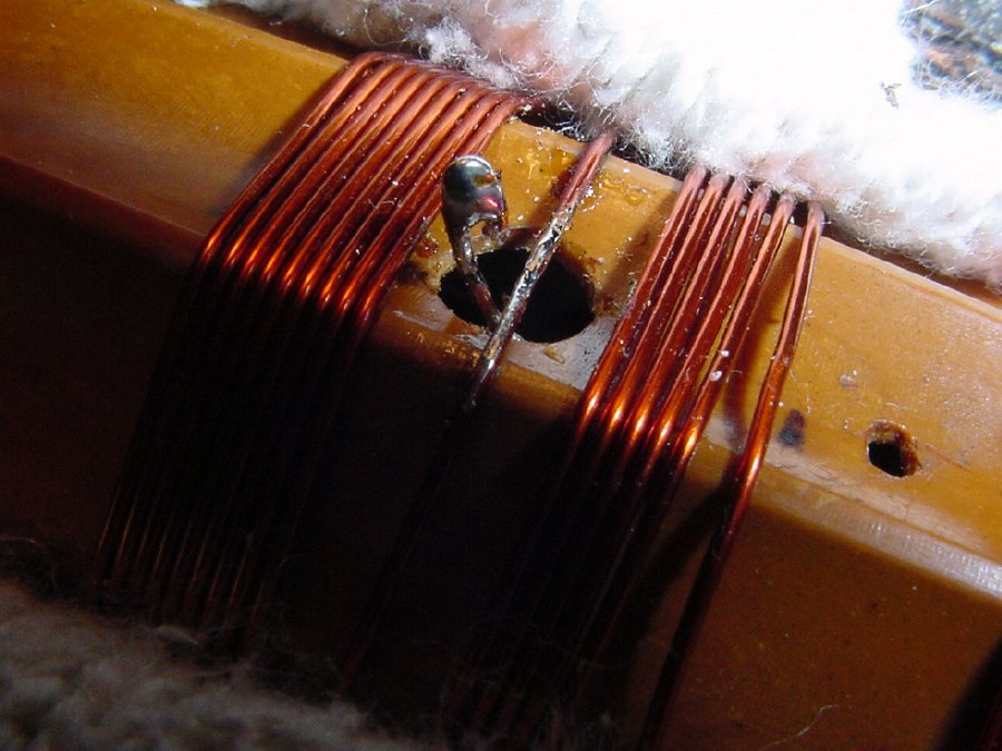
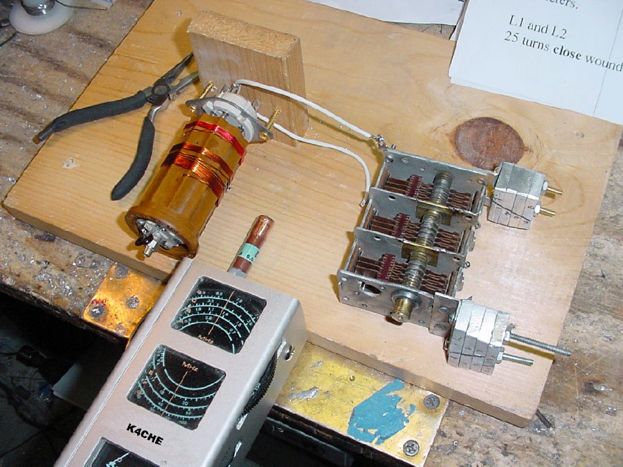
When winding
your coils be sure and use a 1/4 hole for the tap as this allows some
"wiggle" room to change the tap.
You
can compress and expand turns to make small changes in frequency and band
spread but if you do not have the exact coil forms that were used in Mr.
Crosby's article then you are going to have to adjust the taps on the
coils. A quarter inch hole allows you to move the windings up and down
and adjust the position of the tap. Increasing the number of turns
for the tap increases the bandspread.
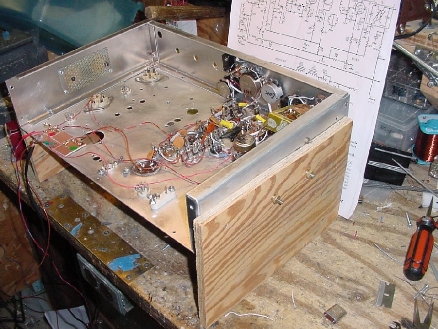
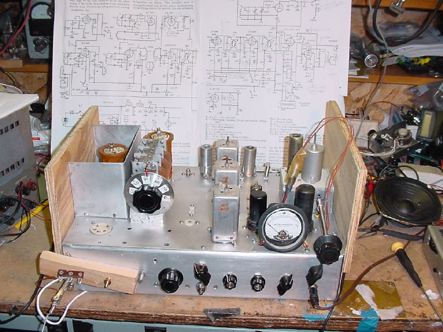
Fabricate
a couple of plywood stand offs for your chassis to protect the
the components mounted on top of the chassis when your receiver is on
the bench.
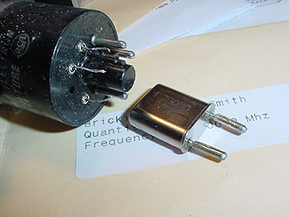
2nd Oscillator crystal. I ordered an HC-6 and soldered on some pins removed from a bad octal tube in order to enlarge the pin diameter to fit the older FT-243 crystal holder.
IMPORTANT INFO
Mr. Crosby choose a 1675 Kc crystal as his 2nd oscillator and utilized 75 Kc IF cans which resulted in a 1600 Kc IF. The HBR-14 receiver as designed was free from spurious products in the amateur bands. In my geographical area I had to choose a higher 2nd oscillator of 1700 Kcs due to a local AM broadcasts station operating on 1600 kcs. Check your local area broadcast station frequencies before choosing a 2nd oscillator crystal.
Using a 2nd oscillator of 1700 Kc and my 85 Kc Command Set IF cans resulted in a IF frequency of 1615 Kc.
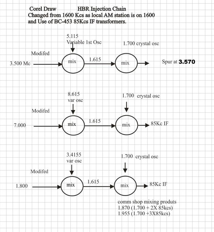
To avoid confusion
with the mixing scheme during testing, make up a chart.
A copy of the July 1957 QST
schematic can be found at:
http://k4che.com/HBR/Schematics/p1p2combinedD.jpg
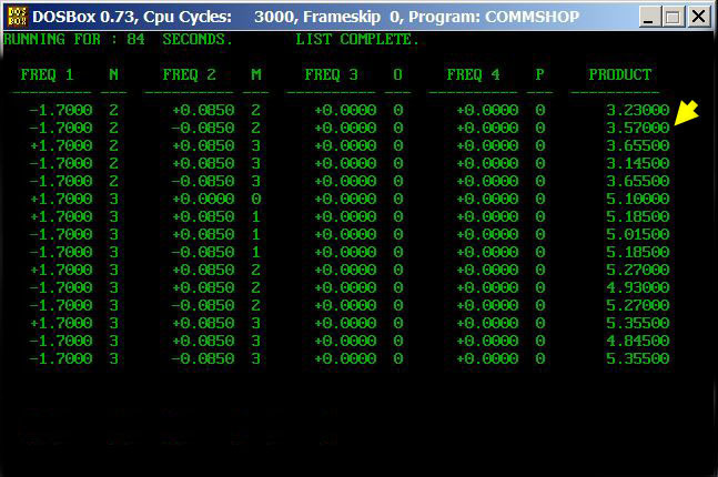
Using a 2nd Osc frequency of 1700 Kc and and the 85 Kc IF cans(Command Set IF cans ) resulted in a spur at 3.570 on 80 meters, but the rest of 80 meters was clear.
(1700)X2 plus (85)X2 = 3570 Kcs
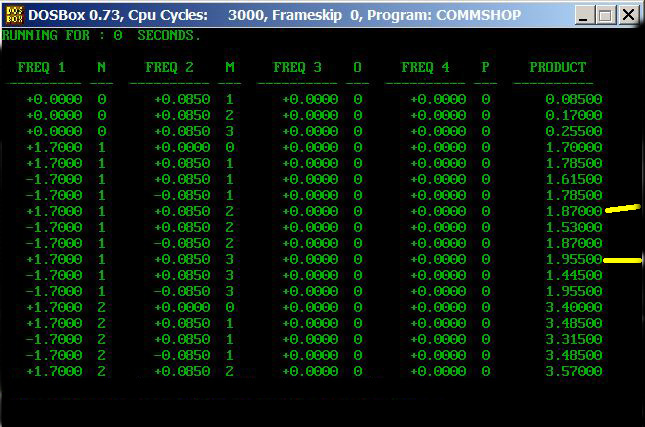
On 160 meters using a 2nd Osc frequency of 1700 Kc and the 85 Kc IF cans resulted in weak spurs at 1870 Kc and 1955 Kc. But I did get good 160 meter coverage.
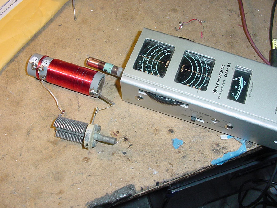
A
quick check of T2 (1600 Kc mixer coil). With a 100 Pf variable the bottom
frequency was dipped at 1300 Kc well within limits. Note when the coil
was installed in the chassis the lower frequency dropped another 100 Kc.

Note
the "gimmic capicator installed.
VIDEO:
2nd Mixer and S Meter Test.
BFO injection testing before mounting the BFO assembly. Don't get in a hurry to mount that BFO assembly.
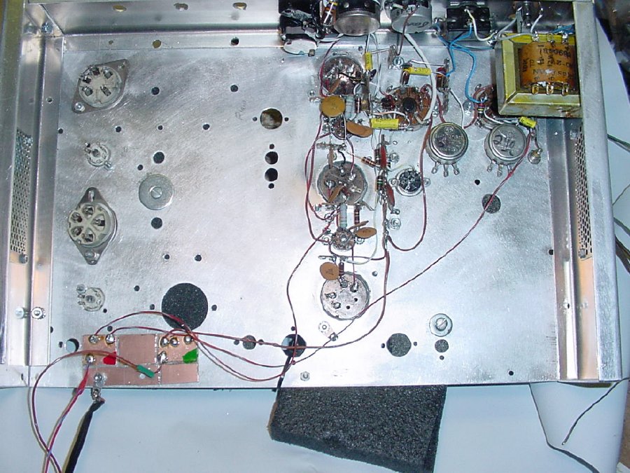
Note the small voltage distribution board mounted on the lower left, the board a piece of PC board with groved sections provides an easy way to supply voltages to your circuits during testing.
I had choosen an HRO PW dial for the finished receiver but for testing I used a temporary dial with a rough scale of 0 to 100. During initial testing this will save a lot of time and wear and tear on your band spread system. You can go from the low end to the high end of the band in seconds.
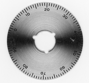
Typical dial, if you do not have one print this photo out and make your own out of thin aluminiun.
Note that I applied labels onto the dial so that it would read correctly when turned clockwise. "0" would be the bottom of the band, "50" indicates the top.
Temporary anenna connecction attached to the front of the receiver for testing.
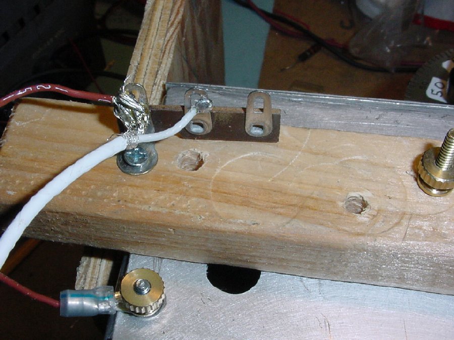
Fabricated from a piece of wood and a terminal strip.

Prior
to finished the 1st RF stage I decided to test the receiver just injecting
the antenna into the mixer via pin 5(output) of the first RF stage.
VIDEO:
Reception using antenna injection direct into mixer.
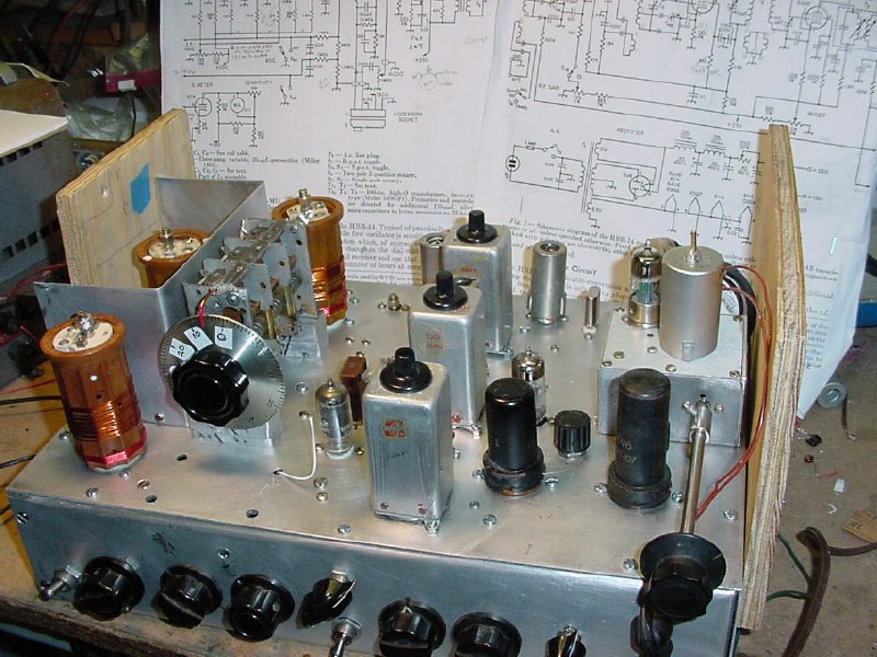
Finally finished but still with the rough dial installed.
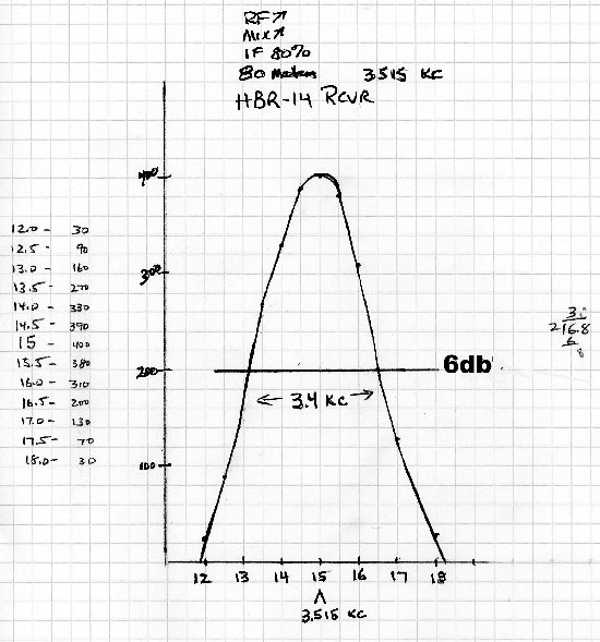
Selectivity curve 80 meters.
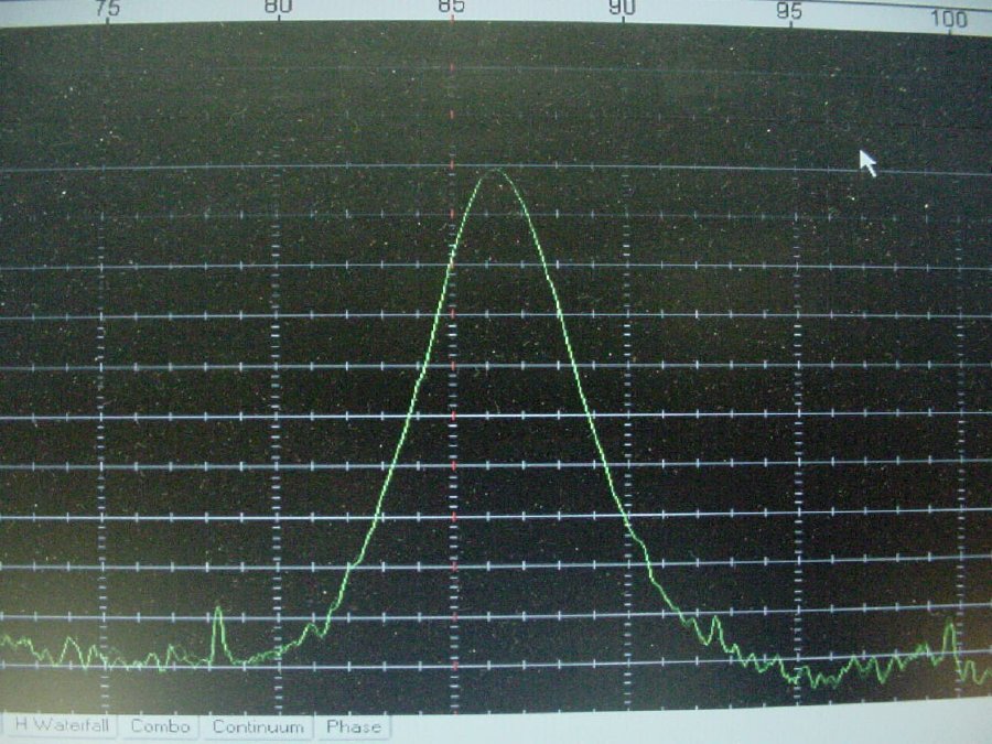
80 meter IF response with sweep generator. Note that the center frequency is around 86.5 Kcs which is slightly higher than the "published" IF can frquency , this was the best response area.
HRO dial installed, a pleasure to tune across the bands.
VIDEO: Testing of gain and other controls.
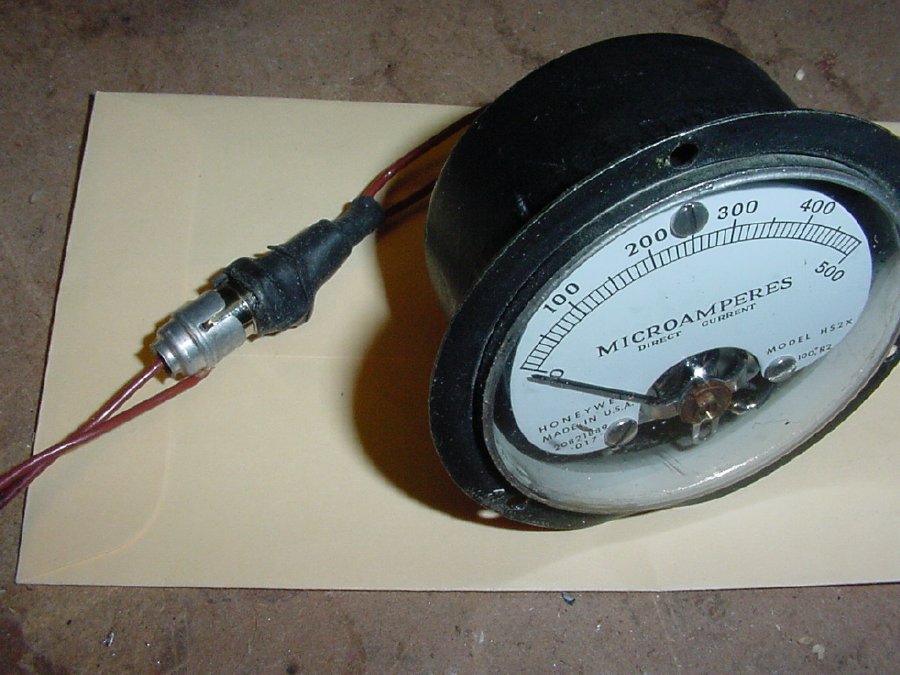
Do
not leave out the S meter circuit. It will come in handy during testing.
NOTE: B plus is presesnt on the leads,
be careful.
A
phono plug was used for quick disconnect.