HBR-14 Band Coils (Oscillator, RF, and Mixer)
A lot of amateur builders shy away from an HBR receiver project because of the frustration and lack of experience in home brewing various coils. Mr. Crosby made a deliberate effort to relieve the builder of some of the "coil winding anxiety" hereto referred to "CWA" syndrome. The result of Mr. Crosby's efforts were "cook book" coils that any builder could wind and utilize and be successful with the receiver RF, Mixer and Oscillator circuits that would properly track across the band.
The good news is Mr. Crosby W6TC was successful in his "cook book" coil design and they were easy to duplicate. The bad news is the 1.25 inch coil forms now are very hard to procure, Walter Ashe and the other supply houses closed their doors years ago. The good news is that I will offer an alternate coil form selection and or fabrication process on these pages. The bad news is the builder is going to have to use simple hand tools and make his own forms or use commercial ready made forms that are slighter larger than the 1.25 inch forms that Mr. Crosby used. The good news is that I have a easy solution to fabricate the 1.25 inch coil form using materials available from you local Lowes or Home Depot etc. The bad news is the builder is going to have to find some "dud" tubes with 5 pin bases.
Some
Coil facts and hints etc.
Lots
of photos and actual construction will be shown below.
1. Before doing anything read all the notes on coils
and coil winding information at:
http://www.qsl.net/k5bcq/HBR/hbr.html#Pic
and be sure and read all QST Technical Notes,"Feedback", etc., a list may be found:
http://www.qsl.net/k5bcq/HBR/hbr.html#QST
2. The builder should be prepared to deviate from
the coil turns and particularly the tap information that was published
in the original HBR series articles. The main reason will be the failure
to locate the exact main tuning variable capacitor. The variable that
you procure will have different values and will alter the "tracking"
and frequency of the circuit.
3. Don't get in a big hurry with the coil project.
4. Prior to winding the coils prepare a printed page with LARGE easy to read instructions with the proposed turns and tap information for each coil. Its hard to remember the number of turns, etc., when you have 25 feet of wire stretched across the room and you are attempting to keep tension on the wire,count turns,keep from tripping over junk on your shop floor and wind and read and etc.
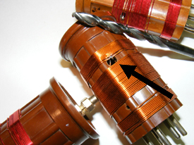
5. Each coil has a .25 (1/4) inch hole drilled in the side. This "wiggle" room allows the builder room to change taps on the coil. Do not get creative and try to use a smaller drill size in order to make the coil look better you will need the larger quarter inch hole for access into the inside of the coil. See number 2 above. I highly recommend that when drilling the hole that you also drill a hole on the other side of the coil to allow half turn variances in the tap of the coil during the band spreading process. See number 2 above.
6. Don't get in a big hurry with the coil project.
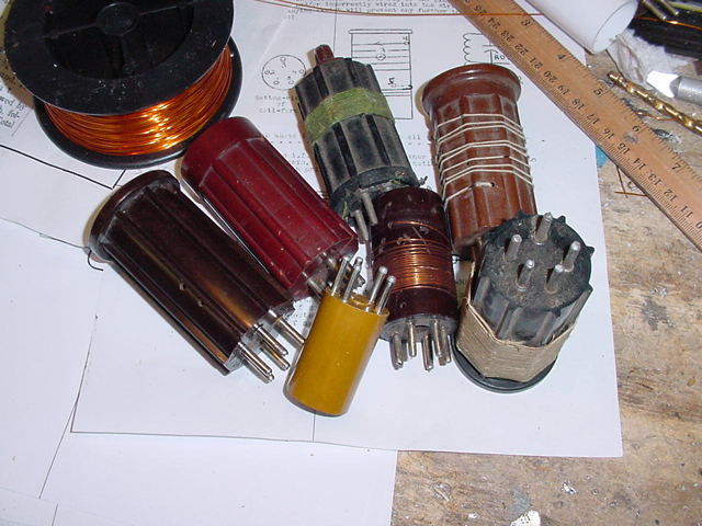
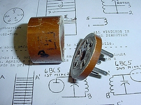
7. The 5 pin coil sockets are hard to locate and you
will find that you will always be able to find two similar
5 pin sockets in your junk box that match but the third 5 pin socket that
you find will be of completely different construction and will not match.
I see no real reason why the builder can not use a regular 8 pin octal
socket and make his home brew coil form using the tube bases from dud
octal tubes.
8. One advantage of home brewing your own coil forms or using commercial coil forms is that you can have more than enough room for winding 80 meter coils, in addition using home brew coil forms and or the standard commercial 1.5 inch form will allow the builder to construct the longer 160 meter coils. More on the 160 meter coils later but for now a warning.
READ
THIS
A builder that might
be contemplating construction of 160 meter coils should ensure that his
enclosure height will accommodate the addition length of the coils. In
order words will you be able to close the lid of the receiver cabinet
with the 160 meter coils in place?
9. Considering the tracking process of the receiver, when W6TC designed the receiver to have "single knob tuning". Single knob tuning in the 1950's was a very big deal, later receiver manufacturers utilized addition RF peaking controls or preselectors to peak the RF section of the receiver or transceiver , for example Collins KWM-2, Drake 2B. With this in mind your tracking priority should be on the oscillator and Mixer section. Remember that there is a front panel Antenna control which consists of a 20 pF variable across the front end RF coil, so you can use this to "touch up" RF tracking as you tune across the band. Its nice to have perfect tracking of all three coils but put your maximum effort into the Oscillator and Mixer coils.
10. Don't use pill bottles or any thin plastic for home made coils. One of the problems with the original coils made of thin polystyrene that Mr. Crosby use is they were subject to rapid melting when soldering the pins etc.
11. Wind the oscillator coil first. This will give a
easier example of tracking etc. as all you will need is a frequency counter
or nearby receiver. Decide now if you are going to use a tube shield on
the oscillator tube,
obviously it will have to be in place during tracking testing.
12. When testing the oscillator coil circuit for band
spread tracking , write down the figures and make a graph to see with
the actual curve of the circuits, a straight line "linear" is
best.
14. There are plenty of alternatives to the original
coil forms on this page so you can no long put off the project by blaming
it on lack of coils.

The
coil forms used by Mr. Crosby in the first HBR receiver were listed in
the Walter Ashe catalog, Walter Ashe was a famous supplier based in St.
Louis. The coil forms were made out of fairly thin polystyrene and when
soldering the wires in the pins the plastic securing the pins would often
melt. Alternatives to the original coils forms are offered on this page.
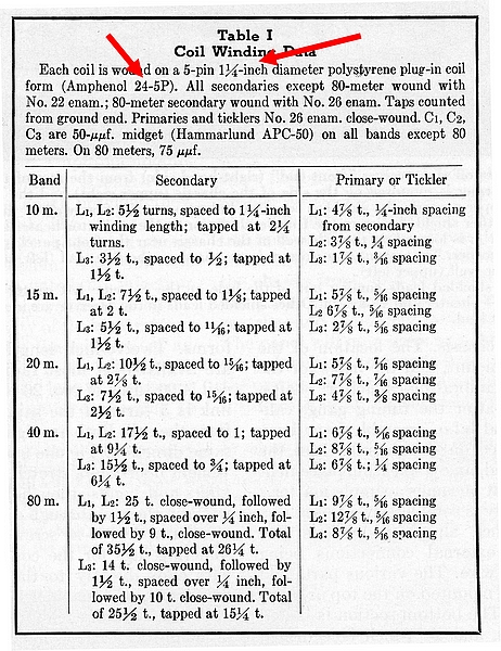
The diameter of the original coil form was 1 1/4 inches.
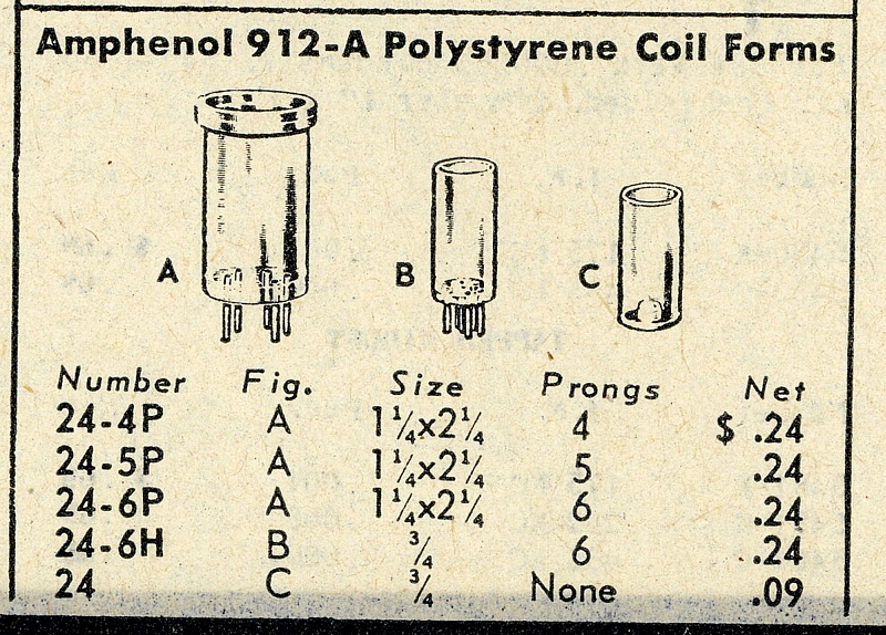
24-5P was the original
coil on the HBR-14. The coil form was fairly short and when winding 80
meter
coils the entire form and often the area near the top and bottom was utilized.
There was insufficient space for the large amount of turns required for
a 160 meter coil.
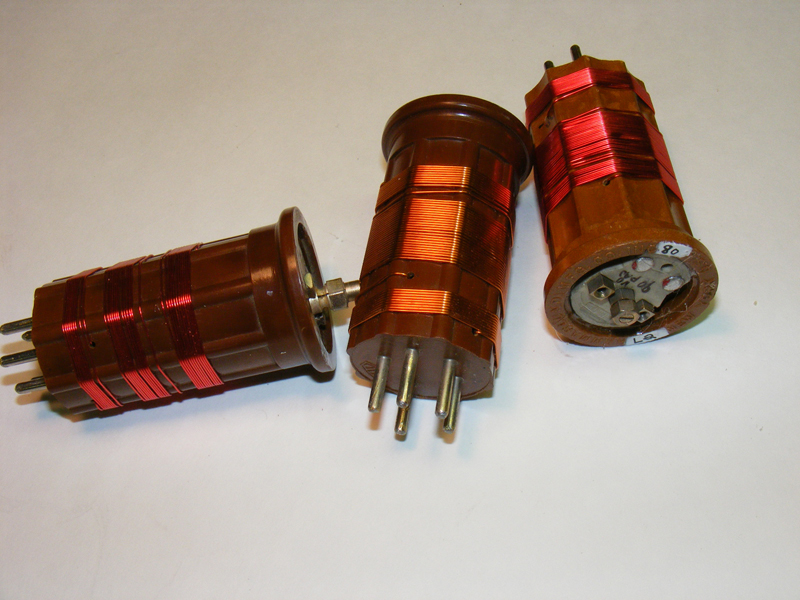
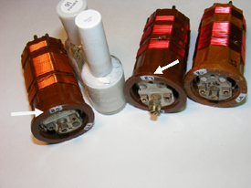
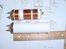
A visit to the next ham fest or eBay should produce commercial 5 pin forms. These forms have a winding area diameter of 1.5 inches, and the total length of the winding area from bottom to top is 2 and 1/2 inches, the winding area length is slightly longer than the original forms.
Found at a hamfest.
The
forms are attractive and give a profession appearance to your project.
However they are slightly larger then the original 1.25 inch form and
appropriate spacing should be made on your chassis. In addition you will
have to adjust the coils for the additional increase in diameter.

Manufacturers
included Hammarlund, Bud, National, Millen etc.
 OD
1.5 inches
OD
1.5 inches
The outer diameter of most of the small commercial forms that I have found is usually 1.5 inches which is slightly larger than the original 1.25 inches originally utilized by Mr. Crosby. Most of the commercial forms were cast in rugged plastic and had a strong vertical rib reinforcement structure. The ribs provide a edge on the coil to keep the turns in place and provide "wiggle" room when soldering your tap and or adjusting turn spacing.
I chose to use this slightly
larger commercial form for my first coils on my HBR-14 receiver and followed
the original coil winding instructions for the HBR-14 furnished by the
QST article.
Fact: No one likes winding
coils, it can be tedious, boring, time consuming, and error prone. My
advice is to wind at least one set of coils while your are building the
receiver and have the coil set finished when you are reading for testing.
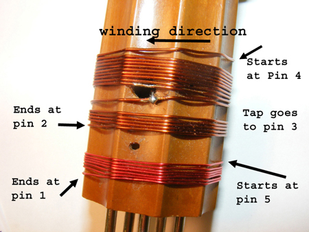
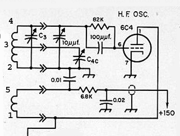
When you read all the "feedback" comments on the HBR receiver
you will stumble the diagram shown above taken from February 1958 QST
and edited slightly.
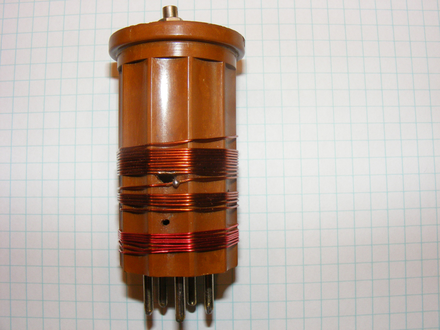
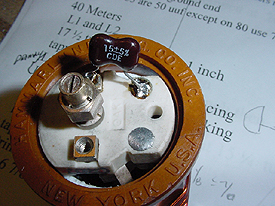
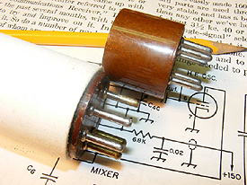
Compare the QST diagram
above with the photo of my 40 meter coil below
 40 meter coil
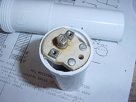
Note
the quarter inch hole which provides "wiggle" room.
Consider just tack soldering the tap until you are sure of its location.
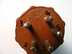
Label the bottom of your coil form to avoid confusion during winding.
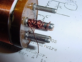
When
you start your first winding secure the end of the wire to the number
4 pin.
When using used coil form, do your self a favor and drill out or enlarge the holes in the pins this makes it easier when you are trying to snake the coil wire through the pins. Clean each pin.
Do not omit the quarter inch hole, this hole is necessary in order to feed the tap to pin 3 and to allow "wiggle" room if you change taps.
Starting with the oscillator
coil L3, after making a graph and checking your band spread you may make
adjustments by compressing or expanding the coils as described by Mr.
Crosby in his many notes on coils.
However if large excursions are necessary then it will be necessary to
move the pin 3 tap on the coil. Moving the tap UP away from pin 2 ground
increases the bandspread. Moving the tap DOWN towards ground decreases
the bandspread.
With a 40 meter band coil
shown above wound using the original coil instructions for the HBR-14,
I found that when I moved the coil tap up the bandspread increases
approximately 38% or a total increase in coverage of 125 Kcs.
By moving the tap down the bandspread
decreased approximately 29% or a total decrease in coverage of
100 Kcs. An option in coil construction is drilling an additional quarter
inch hole on the exact opposite side and this will provide provisions
and "wiggle" room to move the tap a "half turn" for
bandspread adjustment.
On 80 meters moving the tap one turn will result is less change then 40 meters and the total bandspread change was approximately 15 %.
When winding your coils be sure and leave extra space at the bottom to allow compression or expansion of the turns.
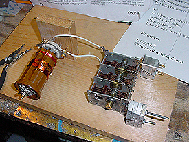
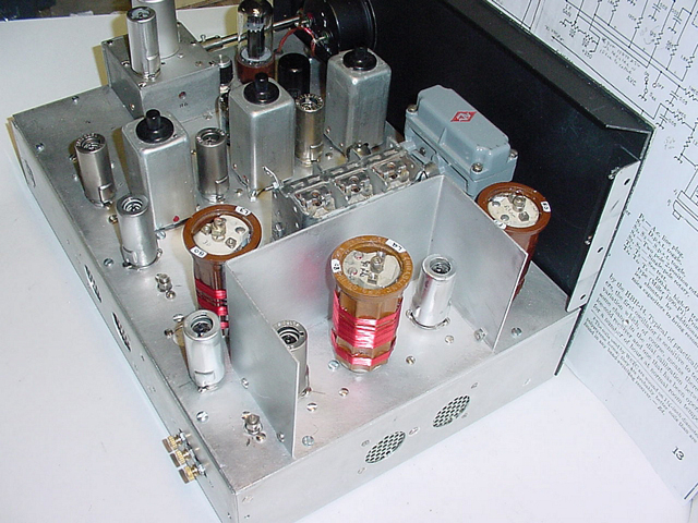
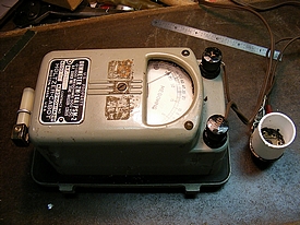
When I decided to experiment with the larger 1.5 inch coils I set up a temporary bench
mock up to simulate the receiver. Using a grid dip meter I was able to determine if I was close to obtaining the correct bandspread of the oscillator coil. This is an approximate test as all circuit components including the tube are not in the mock up.;
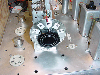
During your testing of Oscillator etc., and to speed things don't mount your fancy dial yet. It faster and easier to use a single knob and you can still graph out your progress. Stick on folder labels mark the dial starting at 0 (variable closed) and ending at 50 (variable open)
Click here Short video demo of the "test dial".
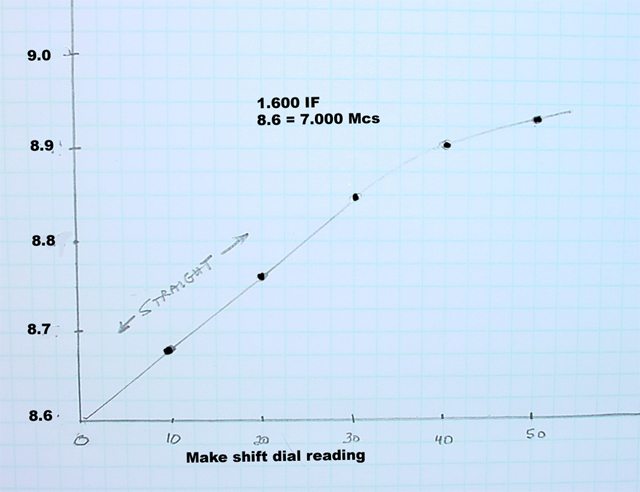
One
of my "rough" graphs to check the 40 meter Oscillator (8.6 Mcs).
The "temporary" dial readings are on the bottom and the frequency
counter readings are on the side. Note the straight line from 8.6 Mcs
to 8.9 Mcs representing the 40 meter band. Well it is all most straight
with just a little curve at the top of the band.
I am using a HRO type dial so really I could get away with a non linear
section. See below
HRO type dial.
 Oops
Oops
With the larger coil I had to move the Oscillator tube socket.
Consider modifying the APC so that you can use the mount holes as soldering points for additional padders. Bill Fizette ,W2DGB recommends using good quality brass APC's instead of the cheap aluminum ones.

The jumper underneath provides a convenient soldering point on top of the APC. Experiment with the value needed for the padder capacitor by spot soldering it in place on top and then after the correct value is determined solder it permanently underneath.
An easy and ole fashioned label can be made using fingernail polish and ball point pin and then coat with a clear fingernail polish.
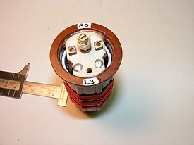 L3
Oscillator coil
L3
Oscillator coil 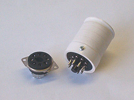
National
RF Inc. Photo
A
final note on commercial coils, National is now manufacturing a 8 pin
octal socket coil that has an "area of 1.3 inches machined for the
actual coil, or coils, to be wound. In addition, a groove is machined
in at the top that provides a convenient finger grip for inserting or
removing the coil from a socket. And with a total of 8 pins available
. . .
I see no reason why the builder could not
use an 8 pin coil and socket, it would be a lot easier to find the 8 pin
sockets as they are readily available. Note that the coil would not be
long enough to wind the 160 meter windings, the 1.3 inch diameter is very
close to the original diameter of the 24-5P coil used in the original
HBR-14 receiver.
Additional
information on the coil forms can be found at Nationals web site.
http://www.nationalrf.com/plugin_coil.htm
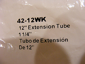
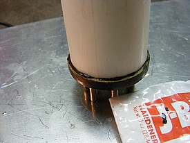
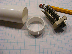
PVC Coil Forms
My goal for construction of a
home brew coil form was to use readily available materials and old dud
tube bases. Most sizes of thin wall small diameter PVC can be found in
the plumbing section of your local Lowes or Home Depot store. An abundance
of the material is usually labeled "sink drain" kits and "extensions".
When visiting your store read the package
carefully for correct size and it helps to be able to measure the outer
diameter of the PVC while in the store.
 1.5
inch PVC shown.
1.5
inch PVC shown.
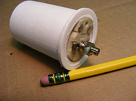
The 1.5 sink PVC fits over the "dud" 807 tube socket(sockets is 1.36 OD) and then the PVC provides a form that is 1.5 inch OD, the larger diameter may require adjustment of the coils, i.e., possibly reduce turns and adjust tap.
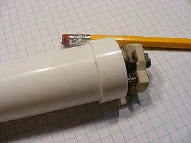
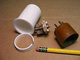 1.5
inch PVC shown.
1.5
inch PVC shown.Coil form parts. The small section of PVC that has a notch cut out is glued inside the 1.5 inch OD tube near the top to provide a surface to mount the APC capacitor. The piece in the rear was cut off of a section near the kit joint and that is the reason for the lip.
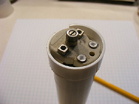
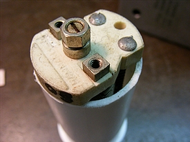
 1.5
inch PVC shown.
1.5
inch PVC shown.After gluing the additonal piece inside the PVC the APC variable capacitor just fits inside the "modified" PVC and can later be glued in place.
Note: For the plates of the APC to move freely and for that you need at least 1.0 inches inner diameter.The "APC" trimmer capacitor was originally designed by Hammarlund many years ago and is an industry standard. On all of the 1.25 inch tubes I measured the Inner Diameter was 1.1 inches.
 1.25 inch PVC
Found in the plumbing section.
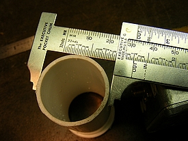 1.25
inch PVC
1.25
inch PVCPerfect
Everything you need for a 1.25 inch coil form.
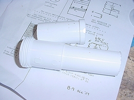
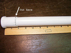 1.25
inch PVC
1.25
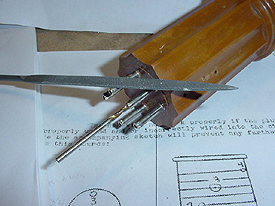
inch PVCYou can use the 1.25 inch tube as is but cutting right above the expansion section will provide you with a small lip at the top of the form. Use a coping saw.
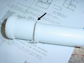
The
cut has been made.
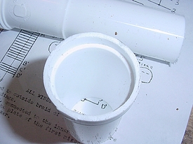
Interior after making the cut. The APC will fit inside the lip and rest on the 1.25 inch section.
Attach the bottom plug with JB Weld. I prefer the 5 minute type.
JB weld is a dark epoxy and is
famous for repairing metal so just in case I checked it out with with
a megger and there was no conductivity.
A perfect fit for the APC
One of my 160 meter coils and an extra long form for future experiments perhaps the lower frequencies.
With the typical "sink kit" you only have a couple of sections that have the built in lip. To prevent waste and to utilize all of the material you can cut off a small section and glue it to the top to form a lip.
Lip is glued in place with PVC cement.
The APC with the fabricated "lip".
Or if you prefer you can skip the lip and glue the APC to the top of the 1.25 inch tube and be done with the project.