One of the Major problems in building a
W6TC HBR receiver in the 21st century is acquiring parts. High on the
parts priority list are the IF coils which are the basic gain and selectivity
blocks for any receiver. Sources for IF coils have literally disappeared
and they are no longer available from distributors so this leaves the
new builder with only a couple of resource choices:
a.
eBay, either find a HBR receiver to rebuild or possible find the actual
IF coils in NOS condition , but be prepared for high inflated prices.
b. Hamfest
flea markets, you might luck out an acquire a HBR part receiver to
rebuild and hopefully the IF coils have not been tuned to death by the
builder. That's what hams do is tune, and retune, and peak.
One of the advantages of the BC-453 IF coils is that they are not tuned
by slugs but by variable capacitors and the variable caps do not wear
out or break easily.
I
have never paid more than $10 for a BC-453 parts set that had the coils.
c. You might try joining some of
the Internet lists such as the HBR Receiver
List and
Boatanchors List , you can query
the list members for assistance.
The builder might get lucky and find the actual IF coils that were used in the HBR series but the odds are against you. So you have two choices either spend years trying to find the original coils or substitute with other coils or wind your own.
My best recommendation for the beginners is to utilized Command Set BC-453 IF coils or ARC-5 R-23 coils that are removed from low frequency receivers that have been gutted. Do not destroy a restorable receiver.
Some advantages of using the BC-453 IF coils are:
a. They are cheap.
b. They are fairly easy to acquire
at hamfests and eBay.
c. The coils are rugged and
are tuned by internal variable capacitors and do not utilized iron core
slugs which often break when tuned. The new builder is going to tune and
tune and retune the IF's because that is what hams do and sooner or later
the slugs break. With reasonable care the BC-453 IF coil tuning capacitors
should last forever.
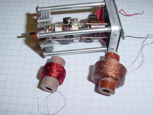
d. Each coil has two internal
coils that are coupled on a shaft , this spacing between the
coils can be adjusted by an external rod and the spacing varied to each
builder individual requirements to increase or decrease selectivity. NO
OTHER coils in the HBR series have this advantage.
e. Both the input and
output coils in each assembly can be tuned and peaked from the
top of the chassis so you do not have to turn the chassis over
to tune the bottom coil.
f. Remarks d and e lend
themselves to easy stagger tuning of the IF's!
|
|
|
Some disavanges of the BC-453 IF coils are:
a. They are fairly large in
size.
b. They utilize a 85 Kc center
frequency and the original HBR utilized a 75 Kcs IF
but this is easy to work around and we will discuss
this minor problem else where in these pages.
c. Mounting can be a small problem
but the details will be covered on this page.
d. You have to find a BC-453
parts set, you certainly do not want to destroy a restorable
radio. Thousands of these sets were highly modified and many were used
as "Q5 ers) The sets were simple connected to the 455 Kc IF of smaller
5 tube receivers and then the BC-453 was tuned to 455 Kcs and with its
excellent IF enhanced the receiver selectivity etc.
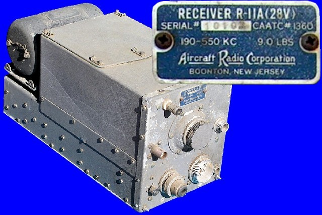
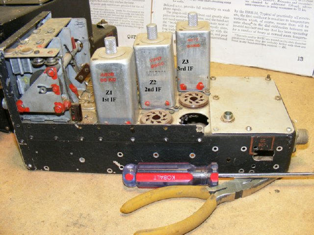
The BC-453 on the right was completely gutted underneath but fortunately the 85 Kc IF coils and sockets were left intact. In addition to the "Command Set" series the IF coils can also be found in the ARC-5 R-23 receivers. Series. See the link below for photos of ARC-5 equipment.
http://aafradio.org/flightdeck/arc5-1.htm
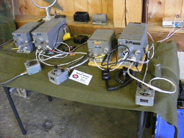
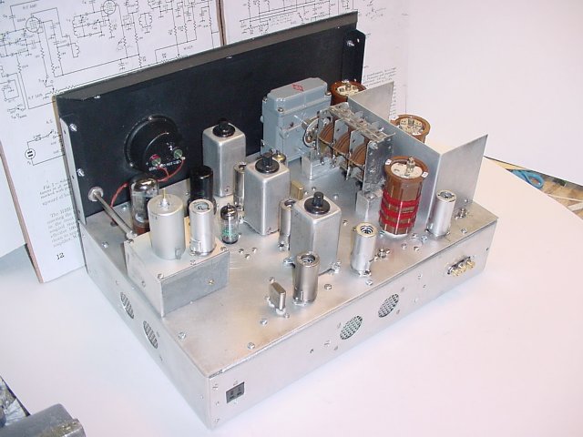
Later on A.R.C. made the type 12 series in the gray cabinet but the condition of these receivers found at hamfest and on eBay is usually very good and I would hesitate harming the receiver as there are a lot of collectors looking for them now and most of them are either functional or can be easily restored. The photo on the right was my Type 12 equipment display at the 2010 MRCA event in Gilbert PA. All of the equipment shown required very little repair and was fully operational.
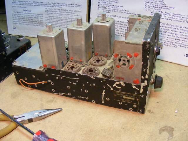
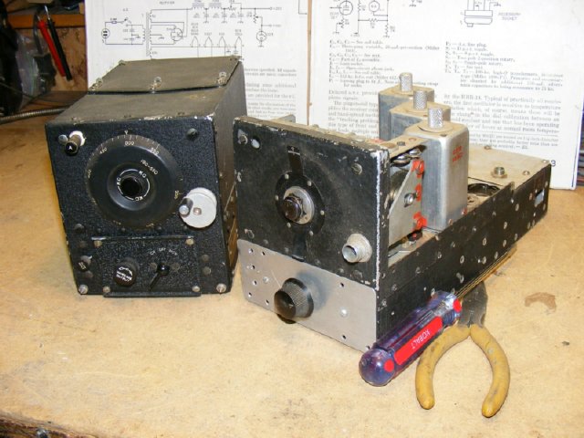
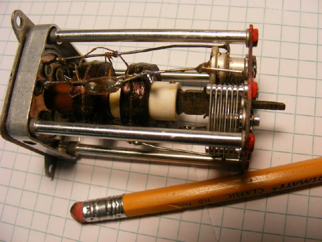
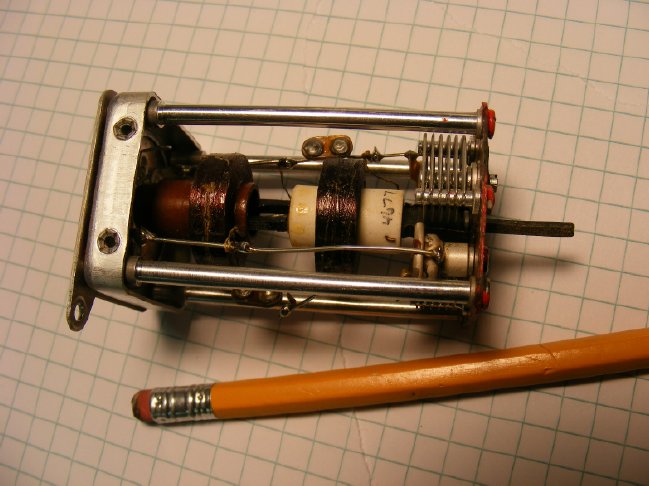
Here are some side views of the "gutted receiver". It had really been hacked,
and was a perfect candidate for pulling the IF coils and using them in a HBR receiver. You might want to
pull the BFO Coil also and it can possibly be used for BFO injection. However I was unable to utilized the BFO coil in its "feed back" configuration in a 6C4 circuit. See the BFO pages for information.
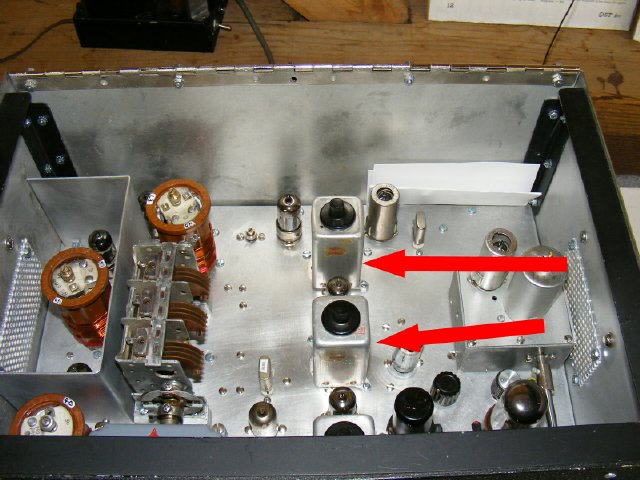
Top component location of the BC-453 receiver.
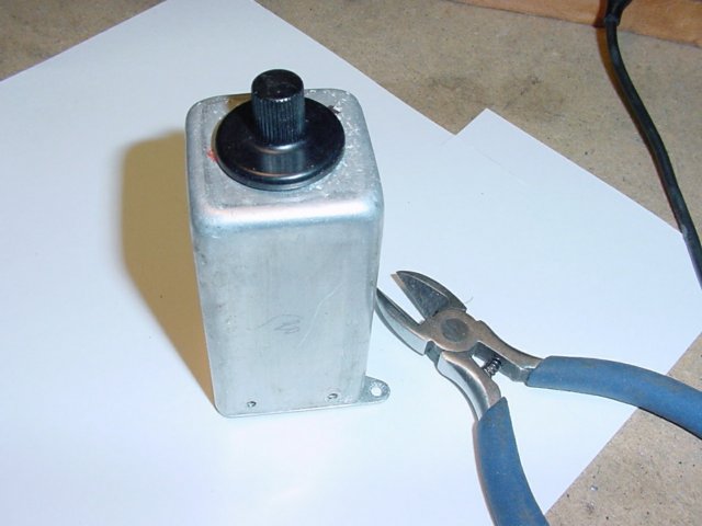
The
IF coil housing has mounting ears and is easily mounted
using
4-40 hardware. The black cap can be removed for access for tuning.
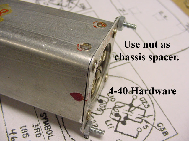
The chassis sockets may be used but they have to be carefully removed from
the donor chassis and inserted into your chassis. I used J-B Weld and simply
glued them into place.
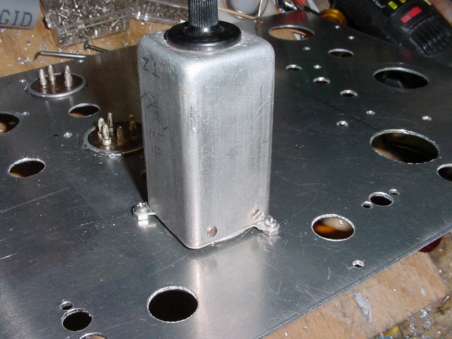
The 4-40 hardware make a simple installation. Note the
empty sockets in the rear.
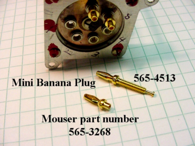
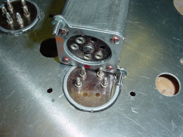
In place of the original sockets small mini banana plugs may be used for the connection to the bottom of the assemblies, this will still allow coils to be easily removed from your receiver if necessary for repair and makes a nice neat installation. Just cut or punch a 1 and 1/16 inch hole to clear the connections and two 4-40 holes for the mounting ears.
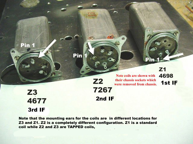
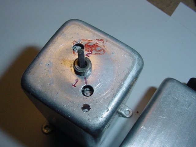
Note that the mounting ears are in different locations for Z3 and Z1.
Also note that the connections are labeled pin 1 and go CCW (counter clock wise)
Z2 is a completely different configuration. Z1 is a standard coil while
Z2 and Z3 are tapped coils. Reason for the taps? Perhaps to reduce the
gain or to set bandwidth.

BC-453
complete schematic.
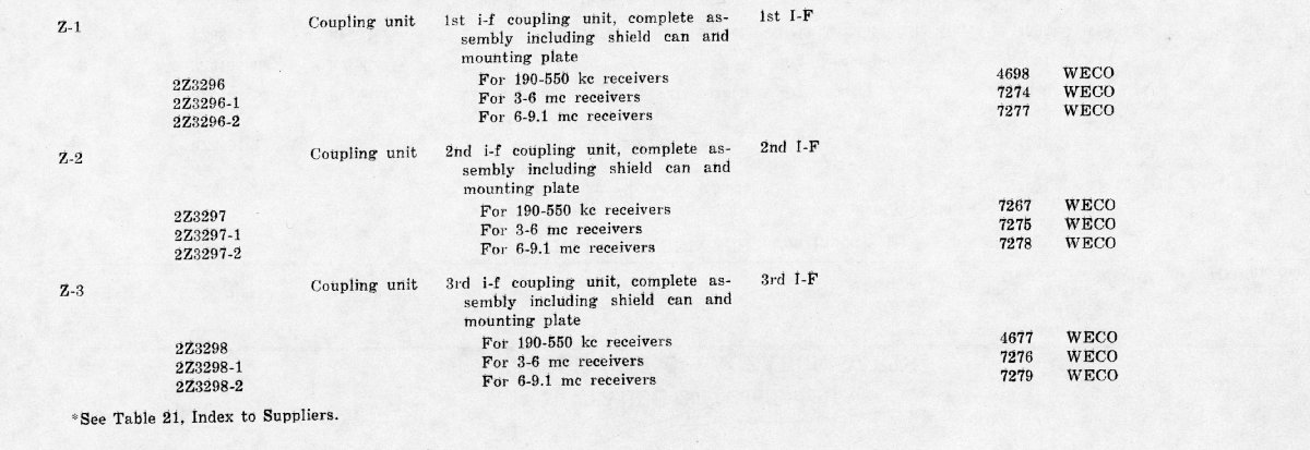
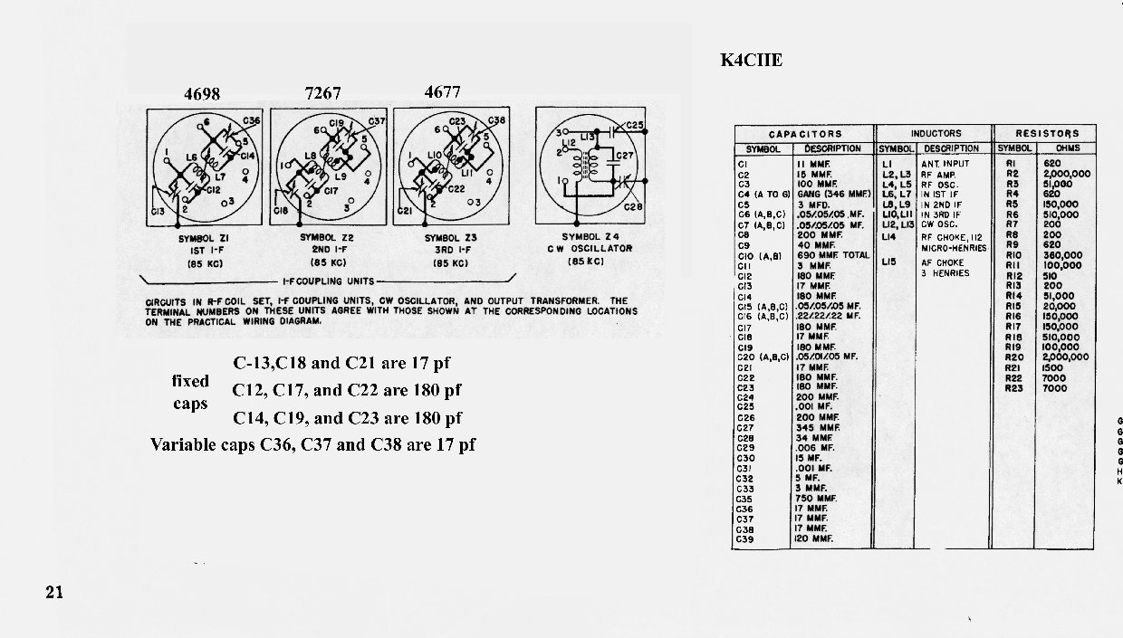
IF coil identification chart.
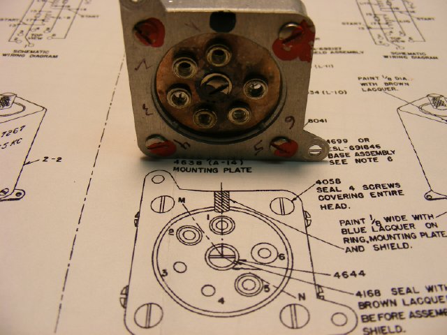
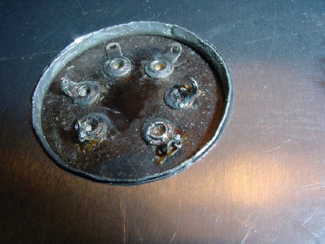
| In this photo terminal 1 is located top 12 o'clock next to the open space and the numbering goes CCW, look at the diagram.
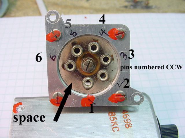
Another
view of the numbering system.
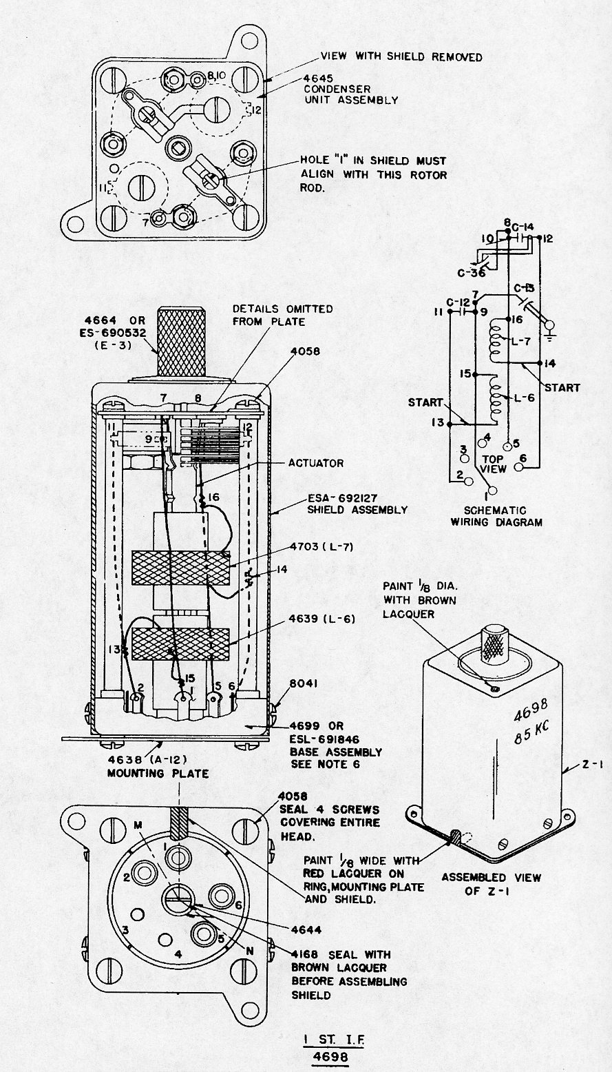
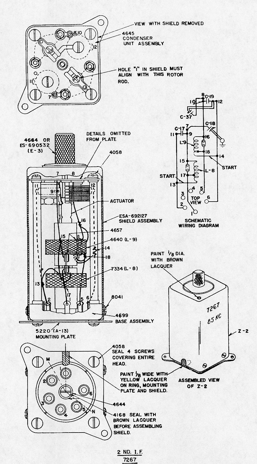
Line drawings for the 1st and 2nd IF
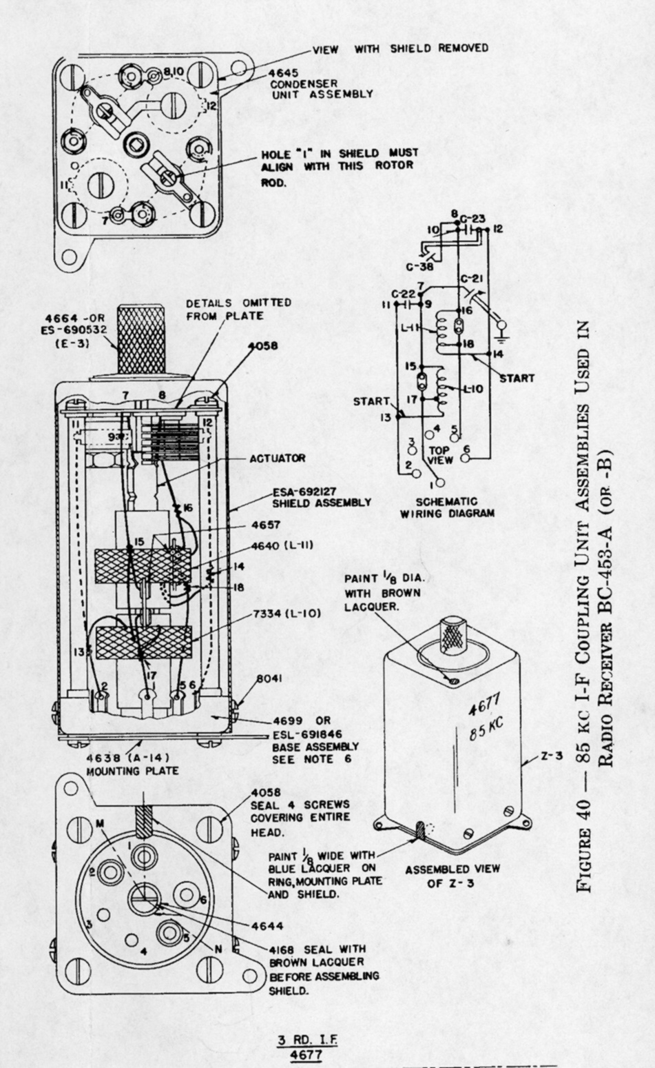
3rd IF
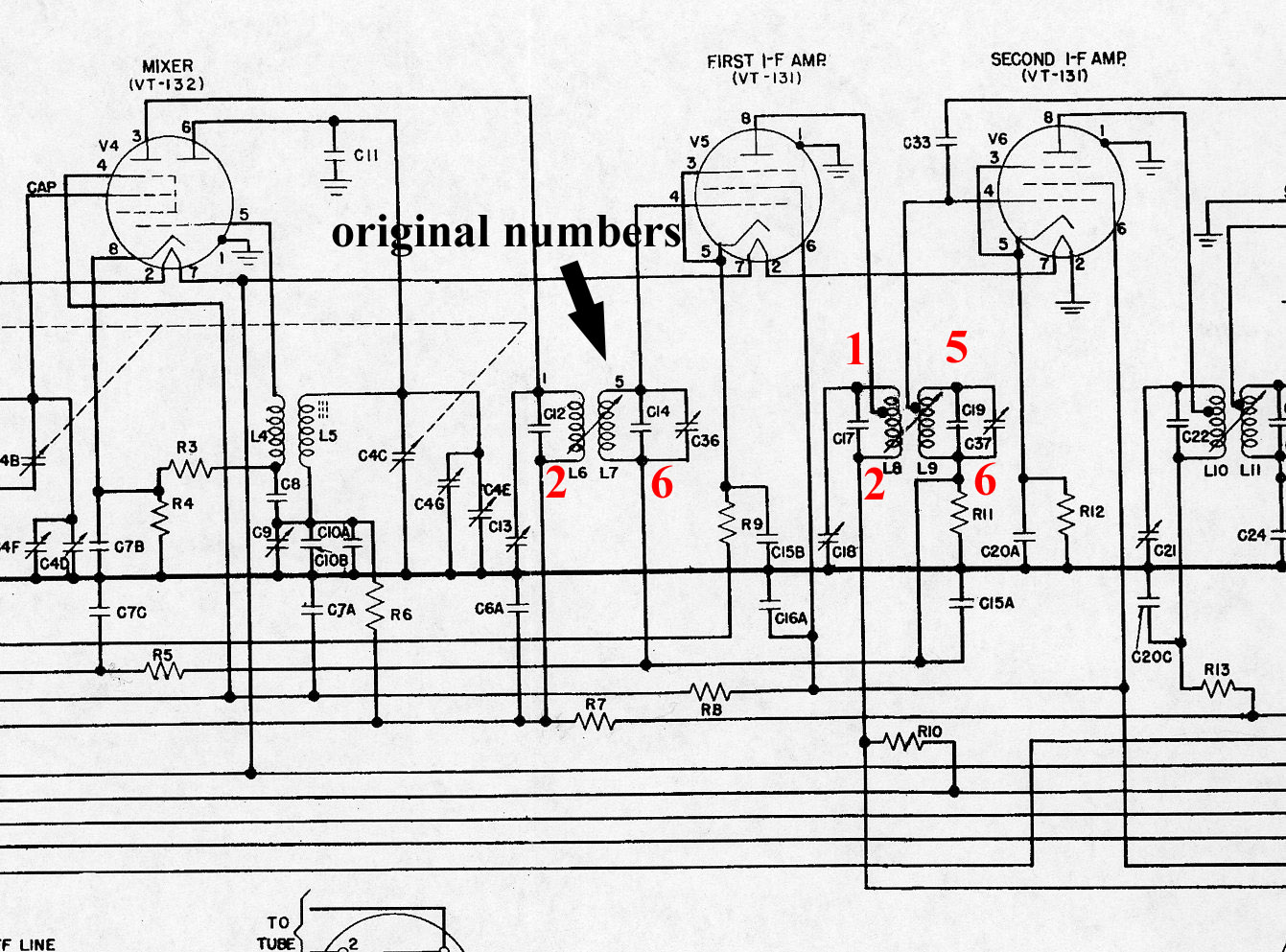
Coil numbers Vs input and output coils.
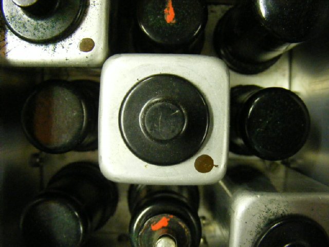
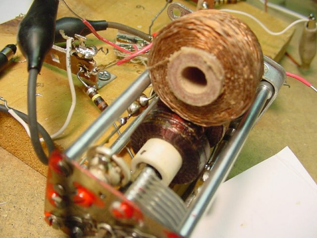
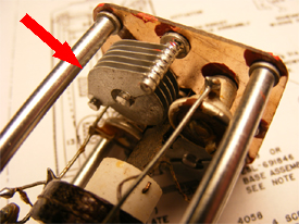
The black cap or sometimes it is a cap made of aluminum can be removed
for access to tuning and the fiber coil tuning rod which varies the spacing.
Coil
spacing adjust rod is in the middle, the two access holes for the
variable caps on on each side. The rod is made out of paper based phenolic
and is fairly rugged but
can break off at the top of the can. .
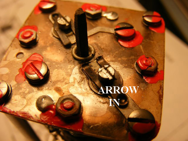
 IN
INNote the "tuning rod" sticking out of the top of the assembly. In this example the spacing between the coils is reduced and selectivity will be decreased for a "wide" bandwidth.
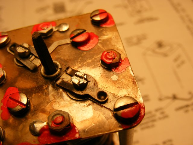
 OUT
OUT
Note
the tuning rod extended slightly and the spacing between the coils has
increased.There is a detent for the rod but it also can be operated outside
the detent for variable spacing to suit the builder. Total vertical
movement is approximately 1/4 inch.
Study
the two photos above and note that you can't do this variable spacing
between coil with Millen IF coils.
Another alternative to IF coils, wind you own but that will be covered in later pages.
Changing the coil to another lower IF of 75 Kcs requires additional
padding of these button capacitors with silver mica caps. I recommend just using the IF coils as is and leave them on 85 Kcs.
Note: Speaking of changing IF frequencies, the original HBR had a first IF of 1600 Kcs, In my area a local broadcast station is on 1600 Kcs so I used a Ist IF of 1.615 to prevent picking up that station. Using the BC-453 IF coils on 85 Kcs requires an crystal injection frequency of 1.700 to reach the IF frequency of 1.615 Kcs. Sticking with the original IF of 1.600 Kcs you will need a crystal on 1.685 when using the BC-453 coils.
Before selecting your crystal check for local AM stations in your area because the extended AM broadcast band changed its frequency allocation and moved the upper limit of the AM band plan from 1610 to 1700 kHz. This occurred in 1993.
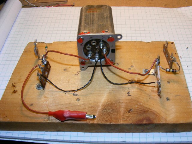
A
test jig for the BC-453 IF coils.
1. First
thing to check is the resistance of each coil. Resistance of the input
and output coils should be approximately 130 ohms for Z1(4698) and 35
ohms for Z2(7267) and Z3(4677).
2.
Checking the tuning of the coils guarantees a working coil and also gives
you a feel
for the tuning of the coil variable capacitors and you can leave them
set centered on 85 Kcs which will help when testing the receiver as the
IF will all ready be close.
3.
This photo has the tuning jig in a configuration for injection a 85 Kcs
with modulation into the terminal strip on the right. On the left
connected to the output is a 1N34 diode detector for feeding a audio amplifier.
Just feed in a "modulated" 85 Kcs signal and tune variable caps
for max signal on your output.

One
of my favorite pieces of test equipment is a Radio Shack amplifiers is
a radio shack 277-1008, has its own 9 volt batter and 1 mV sensitivity.
See my article in August 2005 issue Electric Radio on its use to
as a "Quick and Easy Audio Monitor"
In this configuration you do not need a diode. You can also use your scope, or a VTVM, or even a Simpson 260 was fair in the peak response, if all else fails you can use a digital meter and watch for peak.
Hint: Need a 85 Kcs signal generator? Most "audio signal generators" and function generators go up past 100 Kcs in frequency.
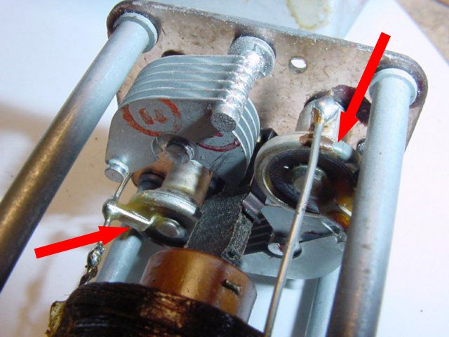
There are two variables mounted in the top of the assembly
When tuning the IF coils
there is a pointer on the end of each rotor shaft which tells you
when the capacitor is at MAX capacitance (IN) min capacitance
(OUT) Note: When checking bandwidth of your coils note capacitor
location in relation to the very small arrow on top of each rotor.
While testing checking for a peak on the BC-453 coils check for peak at max or highest frequency ( Arrow OUT) and minimum frequency (Arrow IN)The difference should be around 3 Kcs between the two peaks. Due to age of the circuit components and construction of the variables the 85 Kc peak may not be exactly at the mid point of capacitor rotation(arrow sideways) During your actual receiver alignment you may find that you get a better overall response at a frequency other than 85 Kcs such as 86.5 Kcs etc.
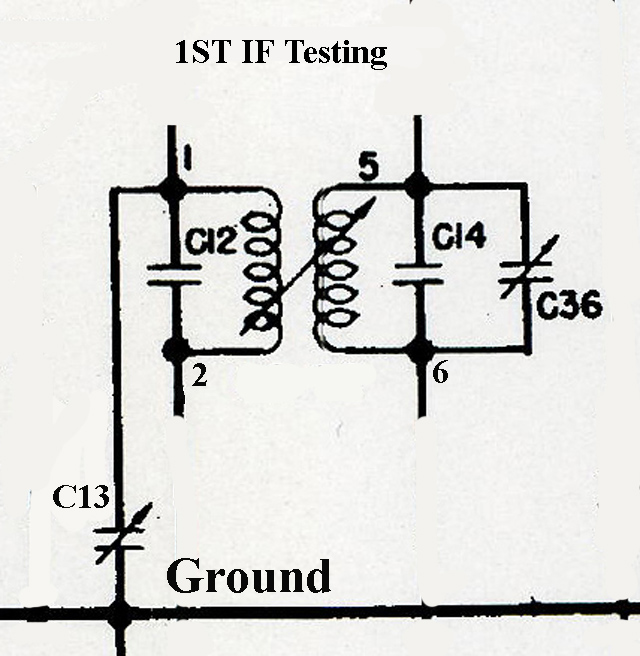
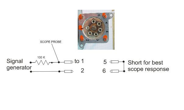
IMPORTANT: When testing the BC-453 coils remember that the input capacitor is grounded to the chassis of the assembly, you will have to connect it to pin 2 for coil testing to place it completely across the coil. In this photo C-13 is on the input and 1 and 2 are the inputs pins. I usually isolate my signal generator with a 100 K resistor to pin 1. Pins 5 and 6 are output terminals.
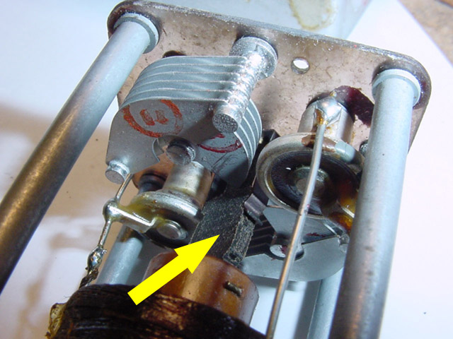
Also
take a look (yellow)at the detents for the fiber rod which controls the
coil spacing..
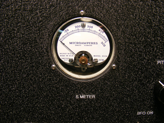
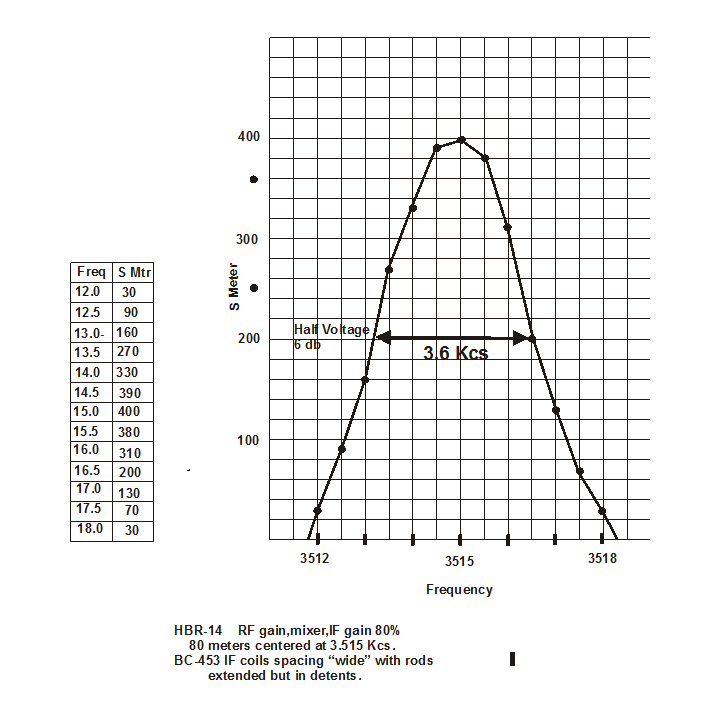
Selectivity
Curve using a signal generator and S meter readings.
IF
coil rods extended for wide spacing of the two coil windings.