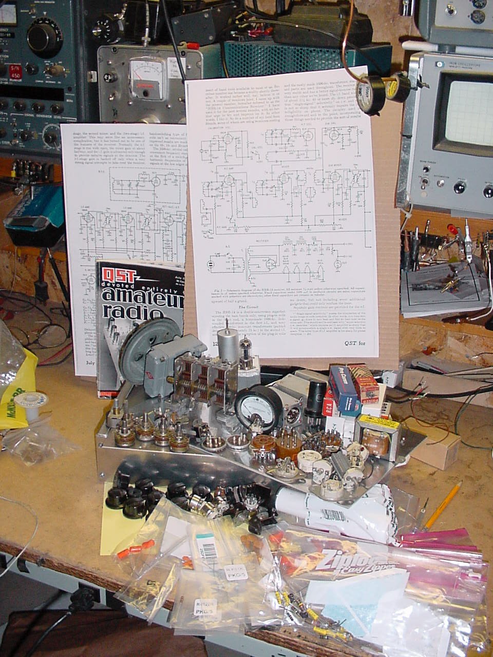
You have to start somewhere but don't delay construction
just to find one major
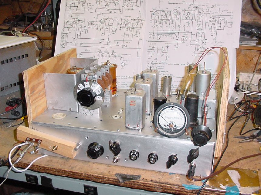
component. Note the enlarged schematics mounted on cardboard,
the enlarged schematic
is a big help during construction, easy to read and you can make pencil
notes beside the circuits.
Don't
forget to update your schematic with the QST feedback changes.
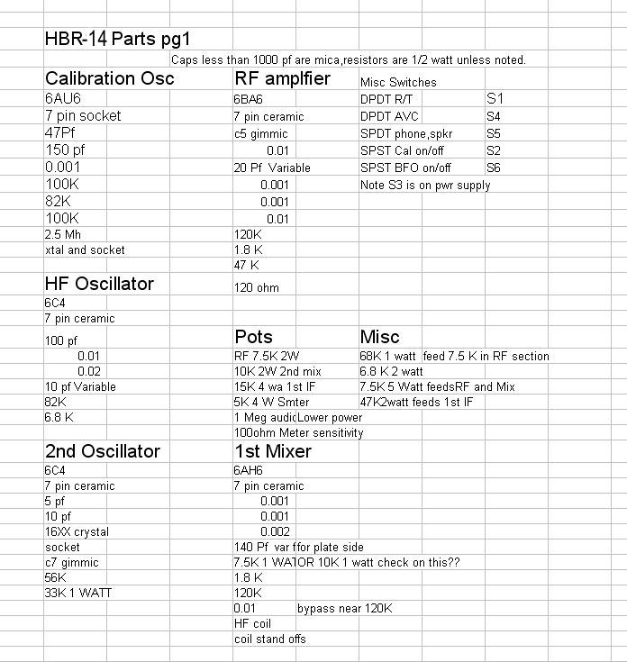
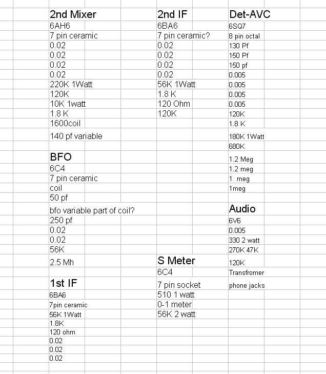
An organized parts list is a must.
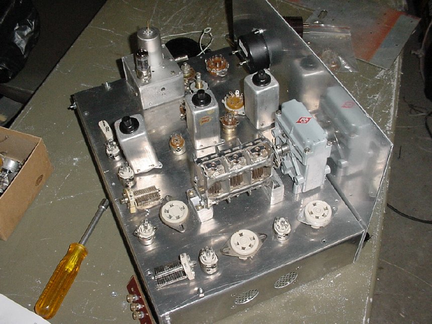
Layout your parts, note that the BFO circuit
housing location will determine where
other components will be mounted. Resolve the BFO circuit and housing
first. Shown is
a "Fred Byers K3IWK Chassis"
Byers Chassis
kits: http://www.k3iwk.net/
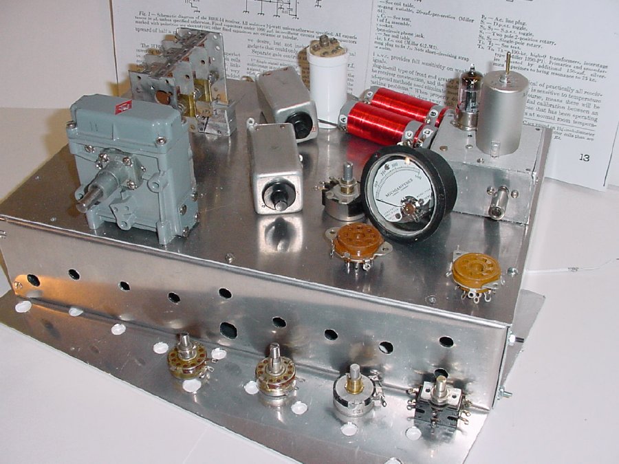
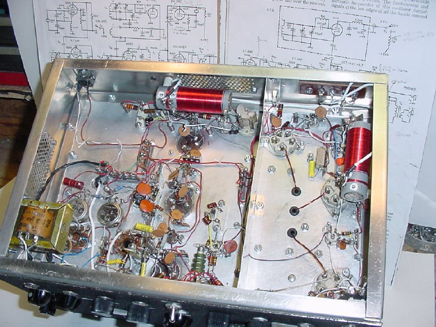
In this photo the BFO is finished, the 1600 Kcs coils are ready
and the variable capacitor mounts are finished. Note that the top plate on the Byers chassis can be
removed for mounting of parts and it makes it easy for initial wiring.
BFO
enclosure is on the left. Note that the power supply
is missing. Do your self a favor and use an external power supply
that is separate from the main
chassis. Less hum problems, heat etc.
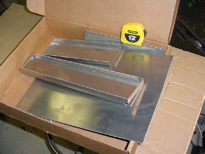
The Byers chassis is a kit. You drill the holes and assemble.
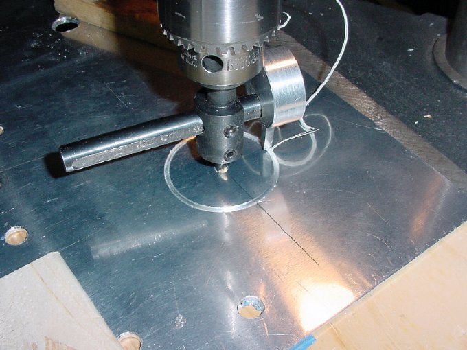
A
circular hole cutter mounted in a drill press is handy.
Do
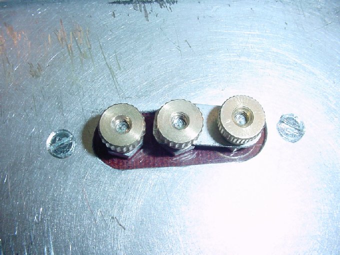
you self another favor and order some decent hardware. Machine
nuts
with built in lock washers are handy for those tight places. Also known
as Kep
Nuts or K-lock nuts.
I
built the original HBR-14 receiver without any major modifications.
Don't listen to those experts, leave the HBR-14 circuit alone and you
will have
a working receiver.
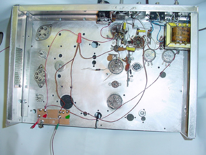
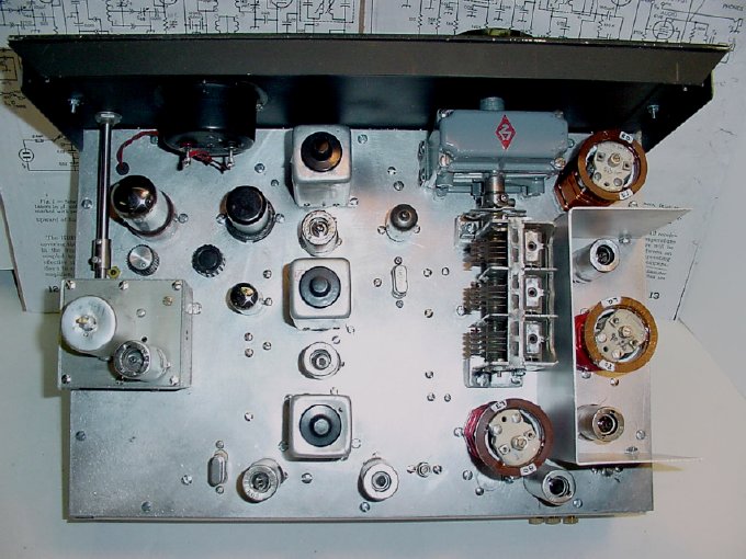
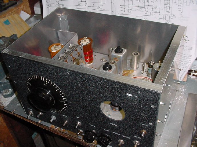
Build the receiver "backwards" - - - start with the audio section first
and you will be able to use it to test the other sections. Be sure and include the
S- meter circuit as it will come in handy during testing and alignment.
Note the temporary power distribution board mounted at bottom left.
Neat
thing about an HBR project like this is you will fabricate lot of odds
and
ends. Shown is the antenna connector.
During
progress testing I tested the receiver without the front RF stage.
The antenna was fed direct into the mixer and the result was excellent
sensitivity.
Note the variable capacitor has
a direct drive knob with a rough scale attached.
This aids in initial band spread testing and you can zip back and forth
from one end of
the band to the other.
I got very distracted at this time
as I had a working receiver and spent a lot of time
cruising the bands. The simple knob and direct drive on the variable capicator
allowed me
to quickly sweep the band to look for signals.
BTW watch out for that S-meter circuit
it can shock the piss out you.
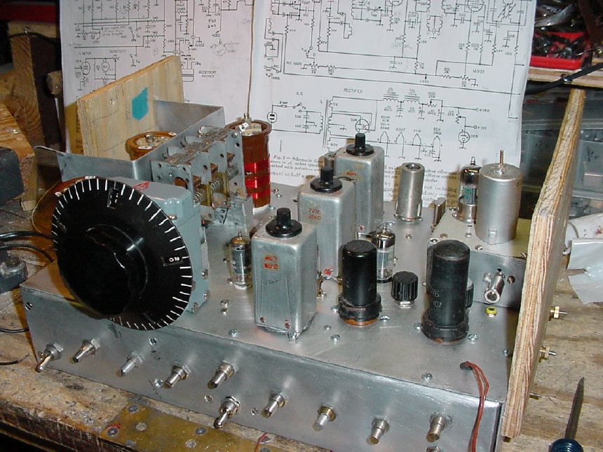
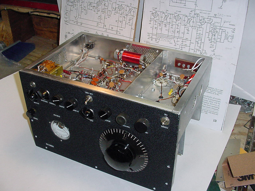
I choose
the older HRO PW knob and drive assembly. The dial has plenty of
band spread and no calibration is necessary, just make up a chart after
the receiver is finished.
The plywood boards mounted on the sides were taken off for final assembly
but protected the
components on the upper part of the chassis during contruction and testing.
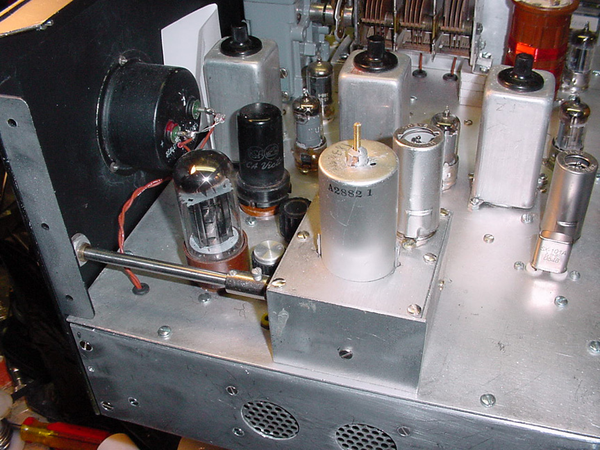
The all important BFO circuit is mounted and an extension shaft is utilized.
A lot of builders will put off the BFO circuit till the last but that is a mistake.
Resolve the BFO issue at the beginning.
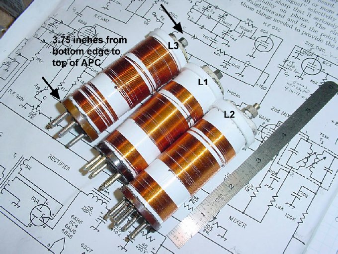
When
considering a housing for the receiver make sure you have vertical
clearance for the 160 meter coils. These extra long coils were fabricated
on homemade
PVC coil forms mounted on cut off tube bases salvaged from bad tubes.
In
order to keep the weight down and to have room for the 160 meter
coils I just made a cabinet by bolting on aluminun sides to the Byers
chassis and then adding
a hinged top. Note the use of aluminum angle on the tops and
in the corners.
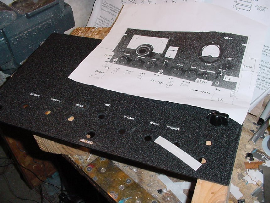
Black wrinkle paint and simple "Brother Labels" covered with clear finger nail polish.
Note the cooling inlets covered with screen on the chassis sides and
rear, much neater than drilling a bunch of holes.
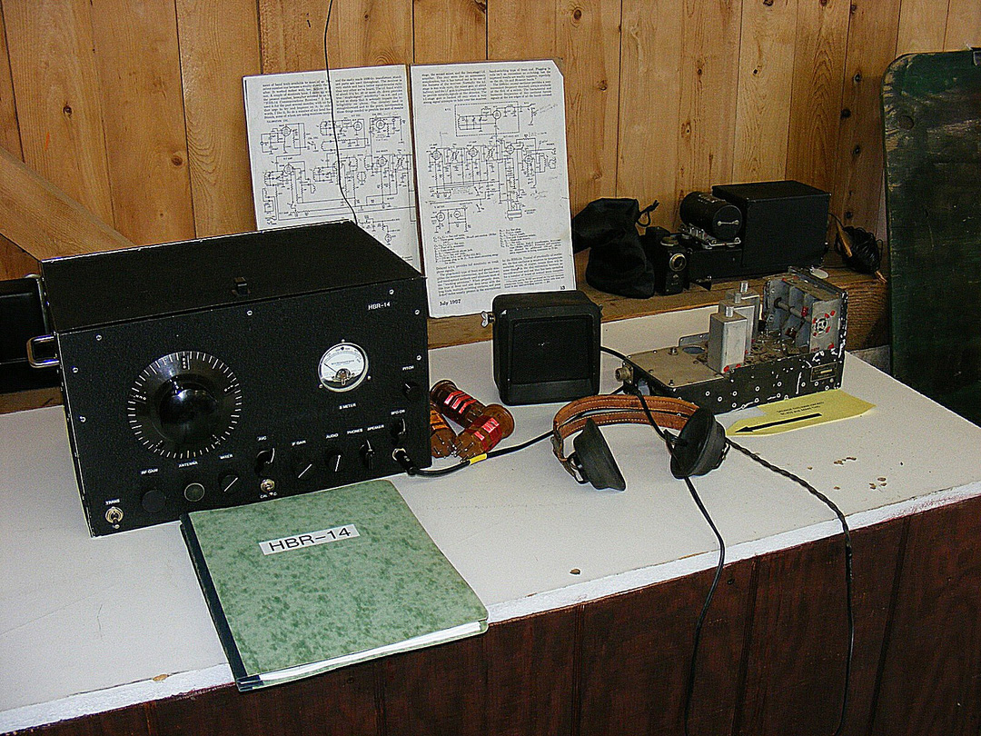
A display at the Gilbert MRCA, emphasis was on the junk command set on the
right being used for something useful.