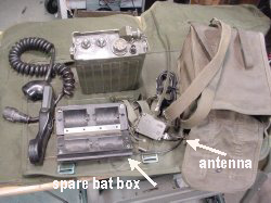
The entire system consisting of bag, radio, spare battery box, and helmet antenna.
 The
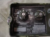
single channel, crystal controlled radio is very compact and has a standard
Handappaarat connector, I used a H33 handapparat. The two knobs control
transmitt power-squelch and lautstarke. The left power control has settings
for 10 Mw(10 milliawatts)with squelch, 50 Mw with squelch and 50 Mw with
an "open" unsquelched receiver. There are no new squelch (PL)
provisions available. The radio can be powered by internal batteries or
external 24 volts.
The
single channel, crystal controlled radio is very compact and has a standard
Handappaarat connector, I used a H33 handapparat. The two knobs control
transmitt power-squelch and lautstarke. The left power control has settings
for 10 Mw(10 milliawatts)with squelch, 50 Mw with squelch and 50 Mw with
an "open" unsquelched receiver. There are no new squelch (PL)
provisions available. The radio can be powered by internal batteries or
external 24 volts.
Tune up and battery
pack instructions are on a separate page on this site. The addition of
a tone board to generate the new squelch of 150 cycles(*) is also described.
*See notes at the end

Click
to enlarge
The mode/power switch on the left is divided into two halves, the left
side is for EB or battery, the right side is for external 24 volts.There
are no provisions for night illumination of the controls making it hard
to use during night ops.
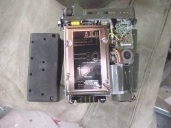
Top view of the radio, everything is shinny and meticulous, looks like space shuttle equipment.
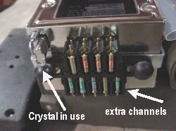
Rear view of the radio showing extra channels and the main crystal in use.
Click
to enlarge
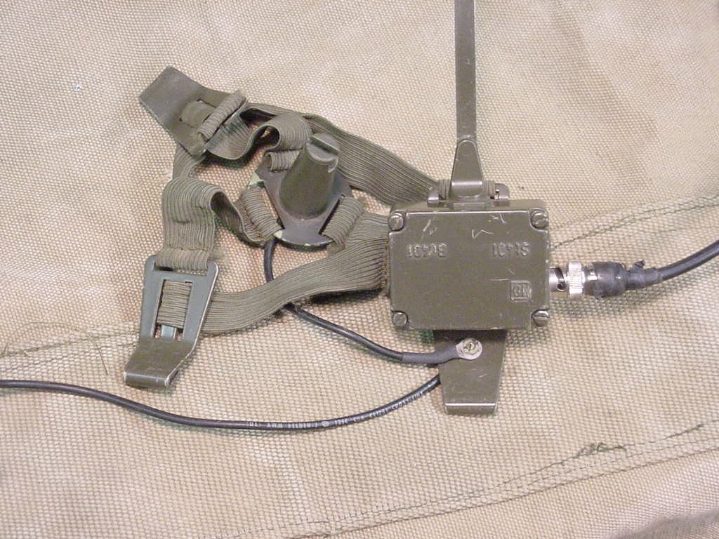
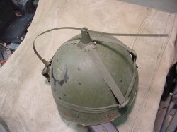
The helmet antenna designed to be mounted on the helmet.
I have added a ground radial to the base so that the antenna can be used
with out the helmet via a short BNC jumper and still provide a reasonable
match to the radio.
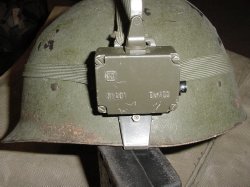
The antenna base is mounted on the helmet and secured with a set screw that bites into the metal.
 The
plastic thingamajig that was attached to the elastic holds the antenna horizontal
to make a low profile for brush, trees,low flying birds and enemy radar.
The
plastic thingamajig that was attached to the elastic holds the antenna horizontal
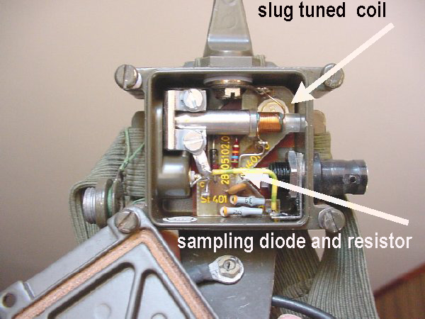
to make a low profile for brush, trees,low flying birds and enemy radar. 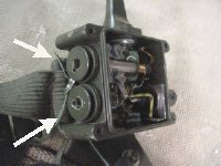 Interior
of the antenna housing. The two round port covers on the left of the housing
can be unscrewed to tune the antenna and to monitor the RF level via a
sampling network. I have not used the sampling port but tuned the antenna
system for maximum field strength after adding a radial to improve the
RF ground.
Interior
of the antenna housing. The two round port covers on the left of the housing
can be unscrewed to tune the antenna and to monitor the RF level via a
sampling network. I have not used the sampling port but tuned the antenna
system for maximum field strength after adding a radial to improve the
RF ground.
Click to enlarge
The antenna loading coil is
the long rod shaped object.The BNC connector on the right goes to the
radio.
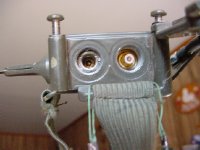
Side view with the two small covers removed. The left hole is for access to the tuning coil, the right hole is the connector for the RF sampling network.
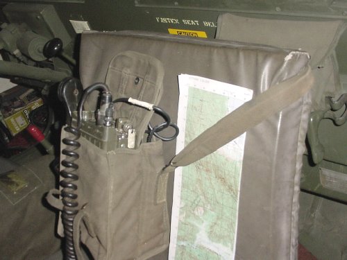
Ready for operations
the radio is slung on the jeep seat and is perfect for short range convey
or squad operations leaving other vehicle equipment open for long range
use.