Most of the information presented here was written by Clayton F. Bane, W6WB in the late 1940's. W6WB is now a SK.
More info on Mr Bane may be
found at: SFGATE.com
Click
on pages and photos below to enlarge.
 I
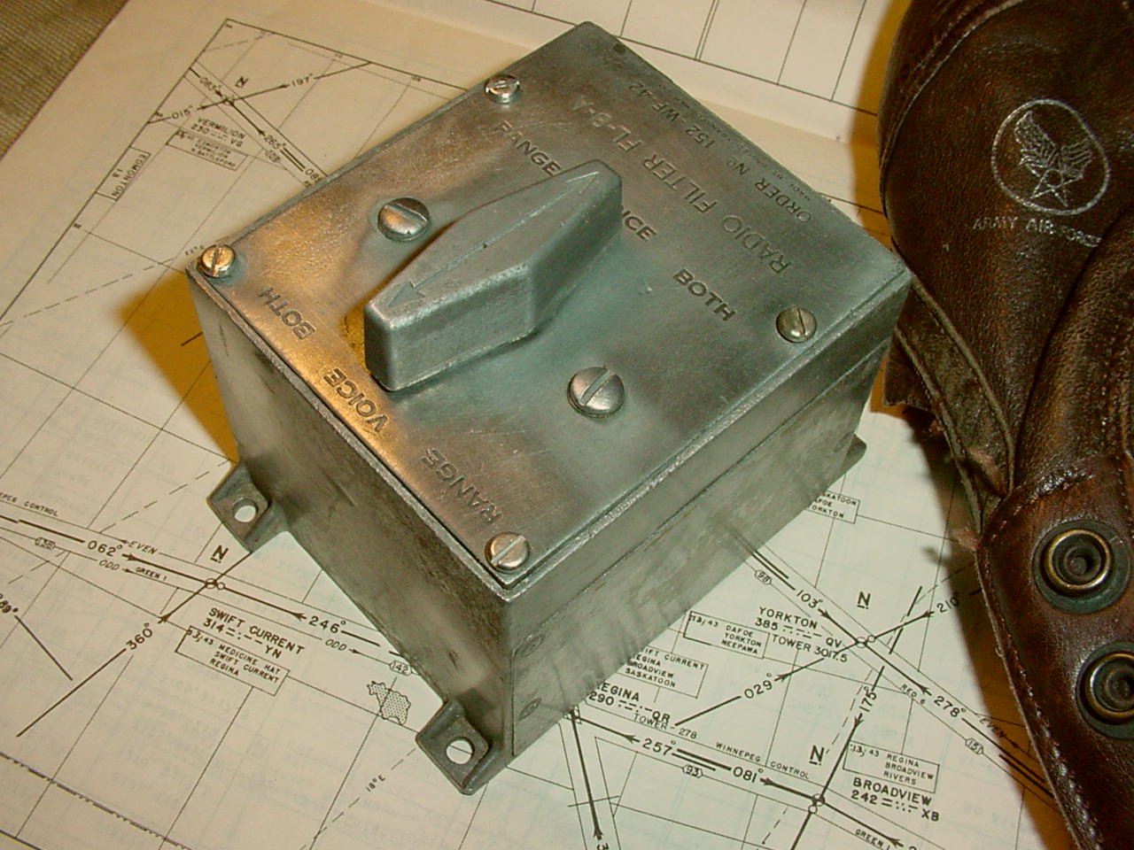
have to wonder just how many of these FL-8's were made? The FL-8
was probably one of the most common aviation communications item ever
manufactured. How many hams cannibalized the knob and the switch and used
them on other projects?
I
have to wonder just how many of these FL-8's were made? The FL-8
was probably one of the most common aviation communications item ever
manufactured. How many hams cannibalized the knob and the switch and used
them on other projects?
How many of these filters are sitting around in junk boxes?
 General Information
The actual tone the filter was designed for was 1020 cycles. The radio ranges used this tone in the transmit audio to provide the Morse code A and N's of the courses. By using the filter the pilot or navigator could filter out the A and N signals and just receive voice audio when voice was transmitted by the ground station. Switching to Range position the voice was filtered out and just the A and N tones would be heard.
Note: The voice audio was used for two way radio transmissions where
the crew would listen on the low range frequency and transmit on a higher
HF frequency. In addition the radio range station made one way transmissions
containing weather and other important information pertinent to the area
that the range transmitter was located in. The one way transmissions were
made at predetermined times which were published in a Flight Information
Publications. The filters were nice but if you flew enough range legs
your brain would filter out the necessary information.
Why the odd ball 1020 cycle tone? The choice of the tone frequency traces back to the use of generating a tone with reference to an electric motor. A common motor speed would be 1800 RPM which would be 30 revolutions per second. The motor had 34 teeth or poles. Multiply the 30 cycles by 34 and you have 1020 cycles. The 1020 cycle tone is still in use today on various navigation aids for the identification. Thanks to Clete WB2CPN for this information.
Click on
the filters below for audio.
Remember when you select "Both" you will hear voice announcements and Range.
When
selecting "Range", the voice is filtered
out this allows the pilot
to Concentrate on the range especially when he is trying to "bracket"
the course.
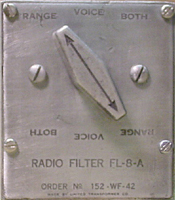 BOTH
BOTH 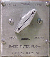 RANGE
RANGE
Note: When listening to the audio you will notice that you can
hear an A and also hear a solid tone. The would be the audio
heard if a pilot was "bracketing" the course. It was easier
to pick
up changes in position by "bracketing" than flying in the center
of the course with just the solid tone. This also provided increase
traffic separation if all aircraft stayed to the right.
VOICE
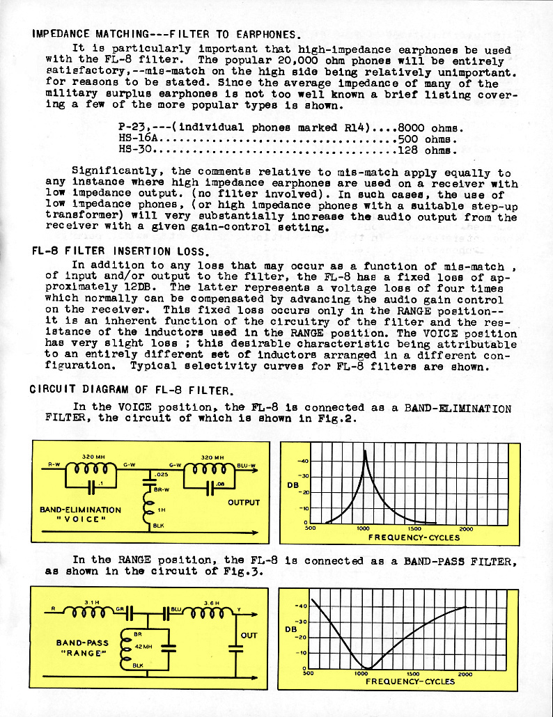
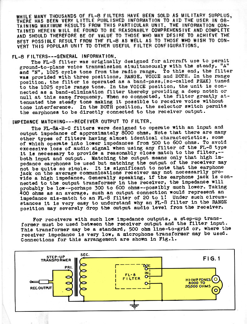
This page contains actual circuit information when the filter is in the Voice or Range position. Note that that a pass and a notch filter are being used.
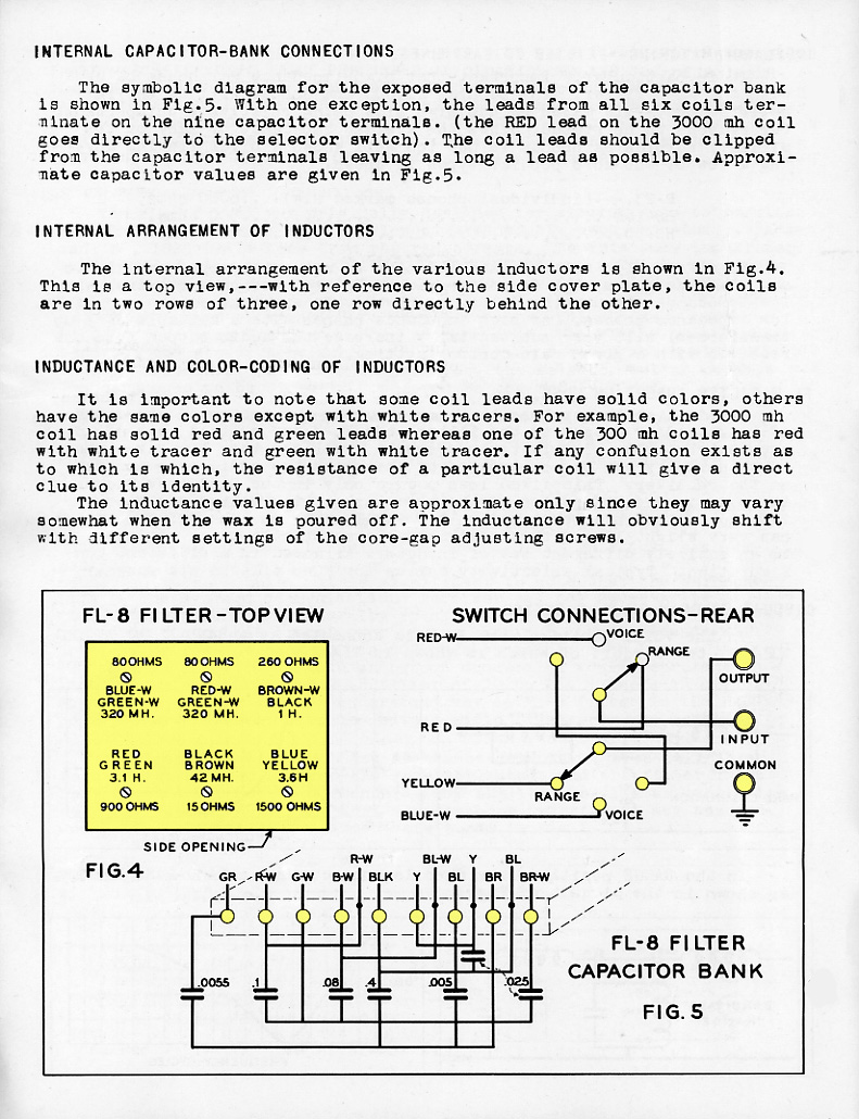
Capacitor, inductor info and Switch wiring.
The Both position is not labeled on the diagram and
is the position where the filter is completely switched out of the audio
circuit. Any time you went to both you
got an increase audio gain and sometimes you would have to turn the volume
down.
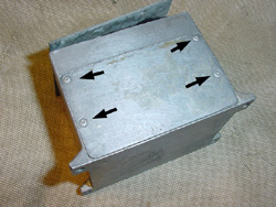
Instructions for access to the internal inductors.
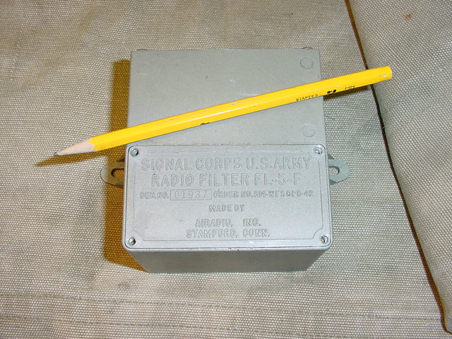 On
the FL-5, remove the data plate.
On
the FL-5, remove the data plate.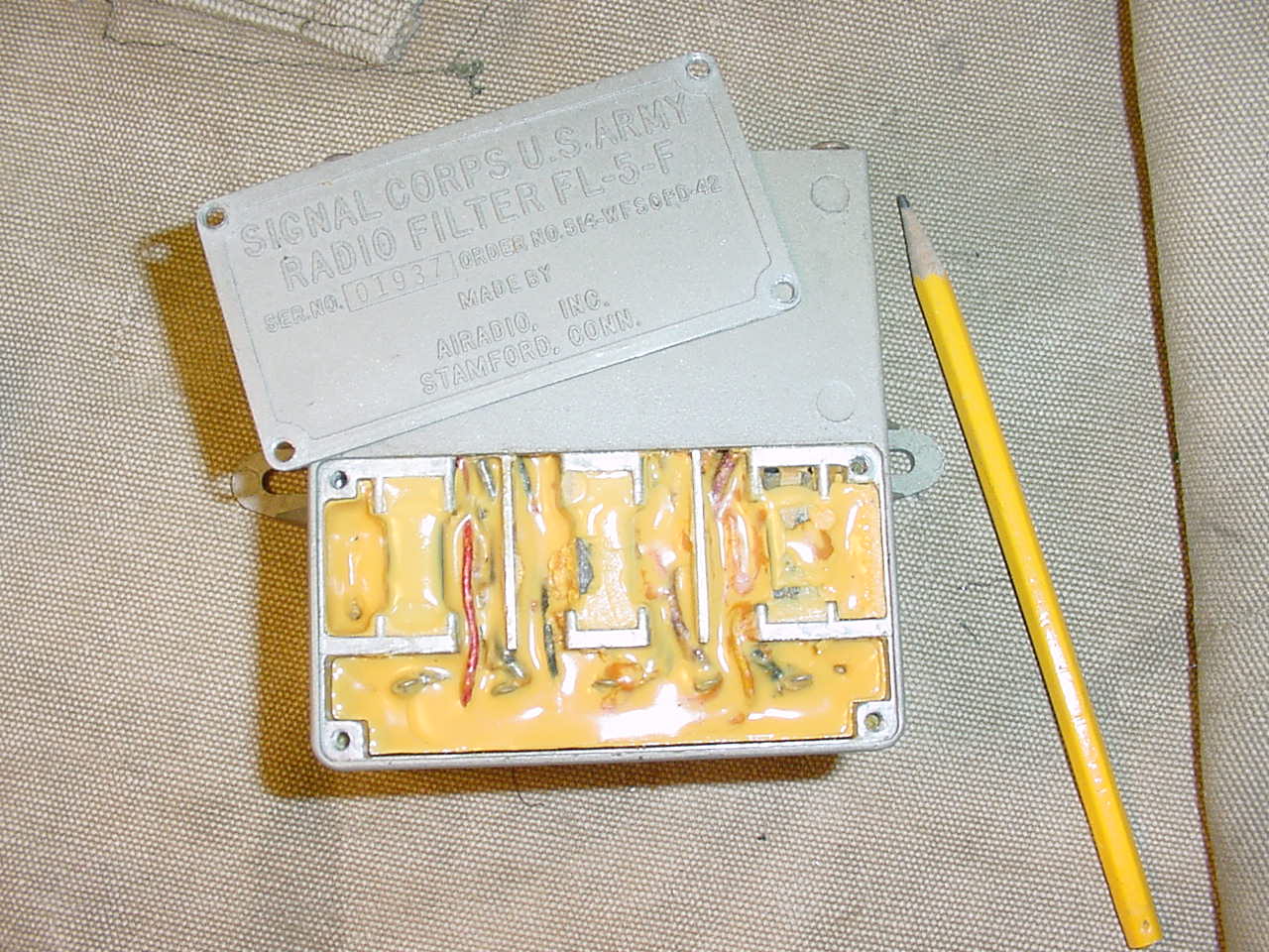
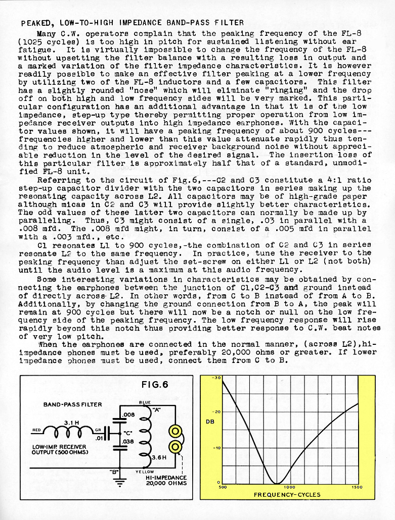
Changing the characteristics of the filter for receiver use.
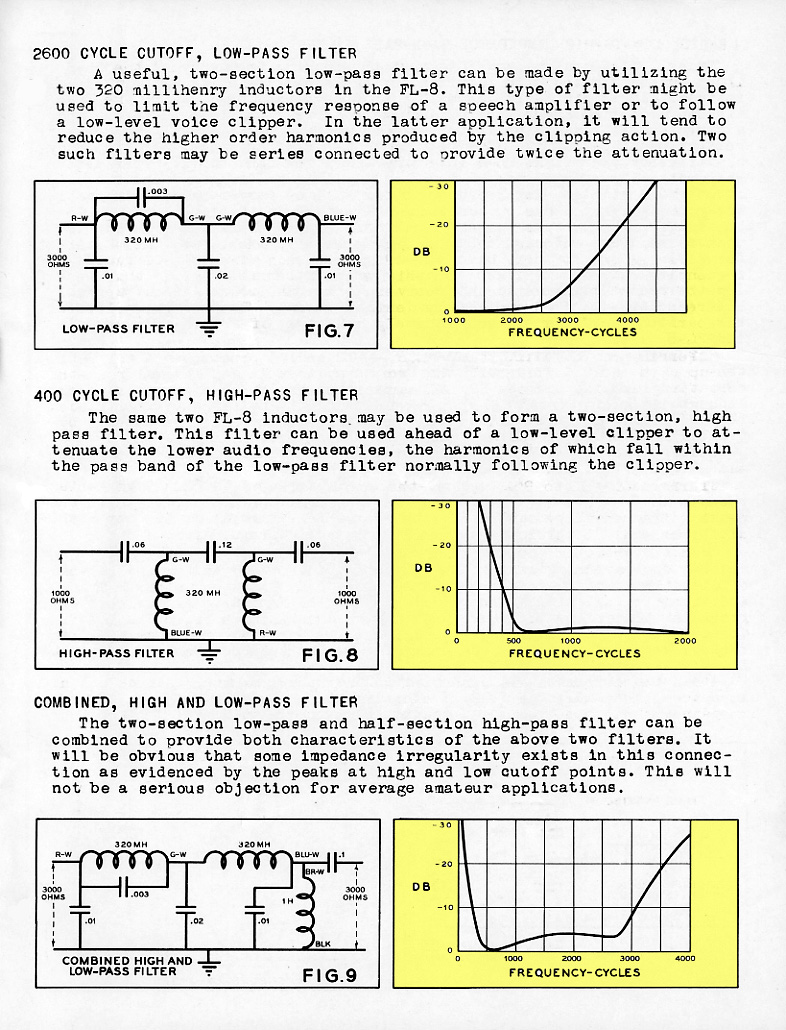
Additional filter combinations.