Some notes on the CN-690. There was a e-mail post on one of the mil lists several years ago that there was a wiring error within the unit.
Quoting the e-mail: "The harness from the handcrank genny to the radio is 'spose to be a regulator, but the resistsor is AFTER the regulator tube, not before it, as it should be! The tube will overheat and burn out if the harness isn't re-wired. Been there, correct that ..."
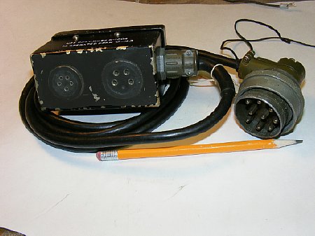
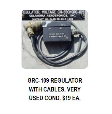
CN-690
Regulator Assembly and Cable for the GRC-109 and RS-1.
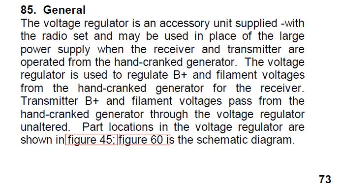
General info from the manual
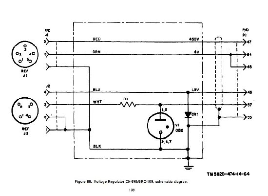
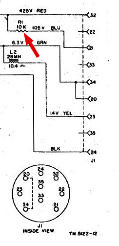
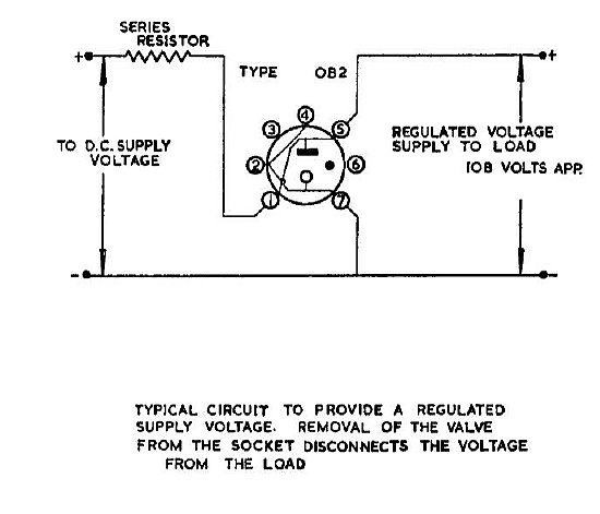
CN-690 Schematic
Looking at the schematic of the CN-690 it does indeed show a resistor "after" the OB2 and there is no value printed on the schematic. The resistor is a 470 ohm 1/2 watt device and is not the primary series current limiter for the tube. Note that the transmitter is not effected. CR1 is a selenium rectifier for the receiver filament
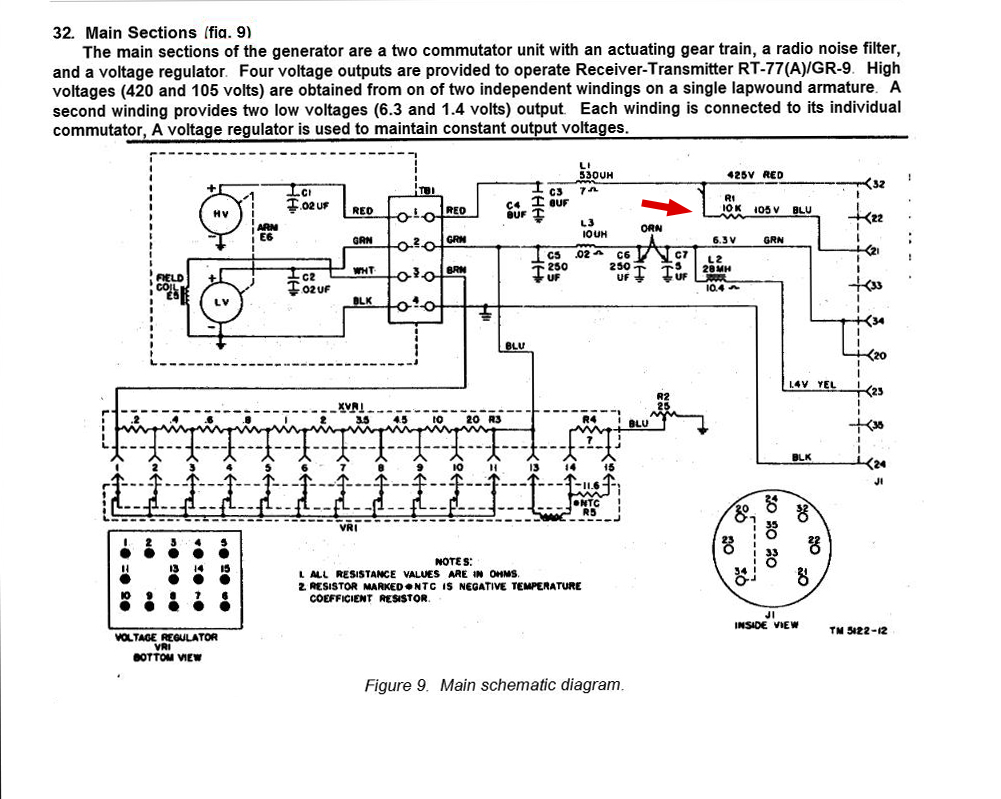
R-43 Schematic
CLICK to enlarge
A series current limiter for the OB2 is installed in the R-43 generator. A 10K resistor is connected from the high B plus line of the generator to pin 21 of the generator power connector. This 10 K resistor is the main current limiter for the OB2.
R-43 generator output wiring.
CN-690 Schematic
R1 a 470 ohm 1/2 watt resistor provides a very small amount of current limiting for the 105 volt circuit and also because of the small wattage ( 1/2 watt) it serves as a protection device in event of a short in the receiver. It is not the primary series current limiter and is installed in the correct position. R 1 a 470 ohms resistor has nothing to do with proper operation of the OB2 (Zero B Two).
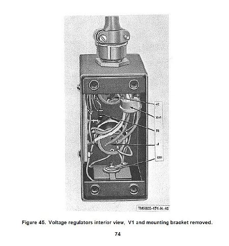
Figure 45
The small 470 ohm 1/2 watt resistor is shown on figure 45 as R1.
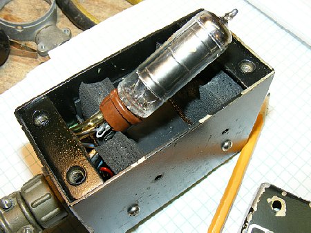
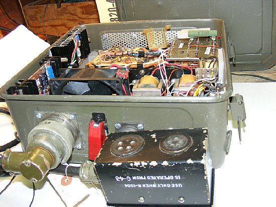
The OB2 rests in a rubber shock mount assembly. The tube can be changed quickly by removing the box cover. You can easily take a peek and see if it is glowing.
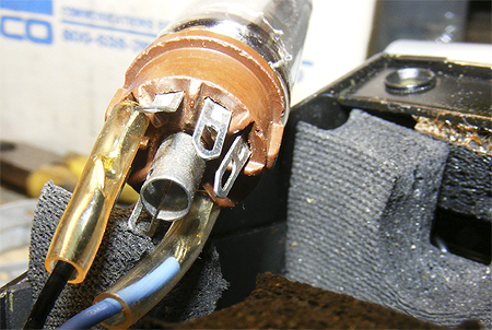
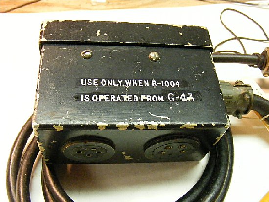
Socket wiring. Only two pins are utilized.
Franks
Electron Tube Page OB2 Data Sheet
Note that in the above OB2 data sheet diagram that when the
tube is pulled the HV will be interrupted which was common practice in
older radio equipment but in CN-690 only two pins are wired.
Franks Electron Tubes pages http://www.tubedata.info/
Last
time I checked Murphy's Surplus they had the CN-690 in stock.
The regulator and its cable can also be utilized if you construct a separate power supply for the RS-1/GRC-109. The power supply shown above can also be also used for the BC-1306 and GRC-9. In any event the constructed power supply will need a high wattage limiting resistor for the voltage regulator tube in the CN-690 with a value of between 10K and 15K depending on your high voltage.
The CN-690 regulator can be used with other generators such as the GN-58 and PE-162. GN-58 schematic below.

GN-58 Schematic
CLICK to enlarge
GN-58 also has a 10 K resistor connected to pin 21
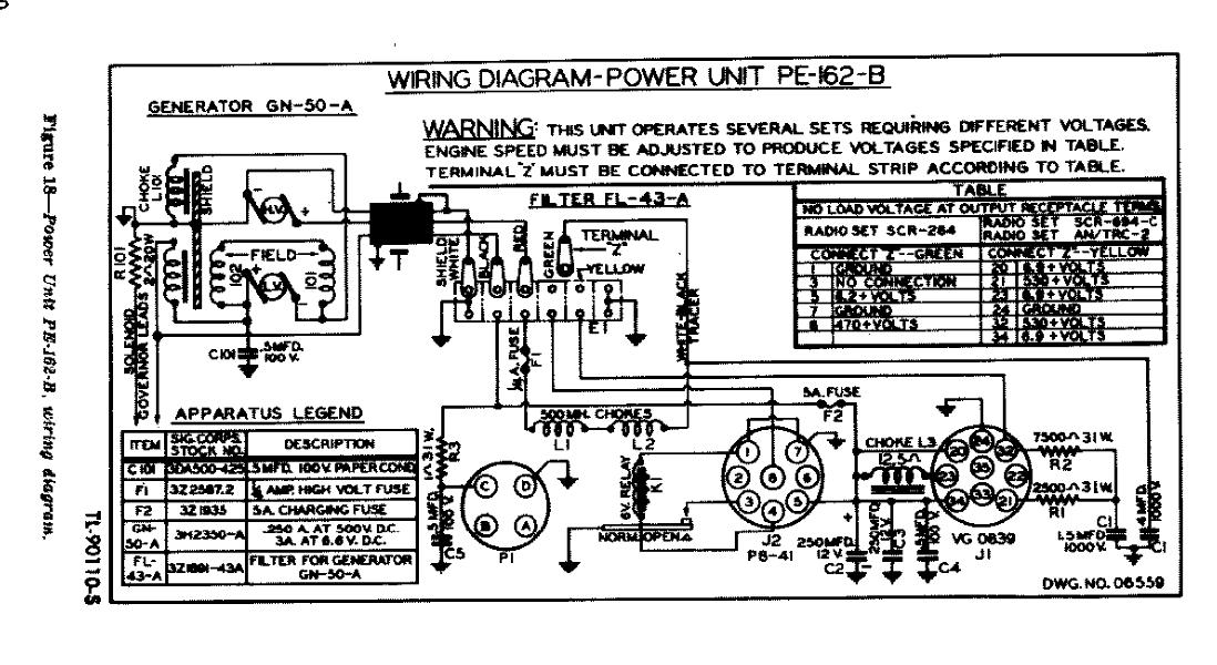
PE-162 Schematic
Click to enlarge
The PE-162 gasoline generator has a 10K resistor - study the schematic carefully.