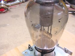
The problem with the 866 tube is that when
it is turned off for long periods of time the mercury collects in different
places on the tube envelope. When you store the tube horizontally this
doesn't help as it collects on the side of the envelope
And here are some additonal notes on the
866 by Clete Whitaker:
" 3 Aug 2013 The mercury will condense on the inside of the glass, that's normal for storage, or in equipment that's turned off. Almost all the transmitter power supplies that used those kind of tubes had a timer that delayed the HV for a minute or more. One transmitter I've put some time on was the BC-446-J, the LF Radio Range. The rectifier tube sockets contained a heater that enclosed the bottom half of the tube. There was a thermostat included in that setup. These heaters were on 24/7, independent of the regular power switch, and made it possible to minimize the time to get the transmitter running from a cold start. Like when the other transmitter, (there were always two), failed. The main problem with rectifiers of that design was contamination by the gases being leached out of the inside components. But the 866 has a very long life. Some of our ranges had someone there 24/7, and two cots were in the room with the transmitters. It was a pre-fab plywood building designed for ranges. The human senses could get accustomed to the noise of the Bohme Keyer doing its "A" and "N", and breaking for a couple of ID's. But the human never got used to the blink at night of the rectifier tubes as the ID, (AM modulation when using loop antennas, or a four-tower arrangement), was keyed. Them were the days. One more thing, Breck, the rectifier tubes that had thyorated tungsten for an emitter would get their surfaces contaminated, (covered), by something leaching out of them, and the fix was just what you're doing. But without the HV. Just a small voltage that would cause the displaced residue to travel over to the anode. Good idea to watch the filament current, and as you are doing, bring it up slow to a higher value than the tube expects. The risk is a weak filament. You need any Variacs? I'll look into the box here. (This little note got longer than I thought it would be, but it also goes into my own "Memory Jogger" file now that I have begun to need such a thing.)" Clete
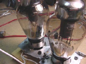
I found some older tube sockets and mounted to a piece of plywood.
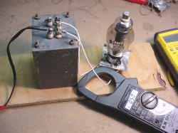
The specs call for a filament voltage of 2.5 and a amperage of 5.0. I usually bring the filament up slow with a variac and let the tube cook for at least an hour. High voltage has not been applied at this time and we are drawing 5 amps.
The large transformer is the 5 volt filament transformer, rated at 5 amps. I wired the two 866 tube filaments in series as I did not have a spare 2.5 volt transformer and applied 5 volts. The smaller transformer being used is rated at 600 volts with a center tap.
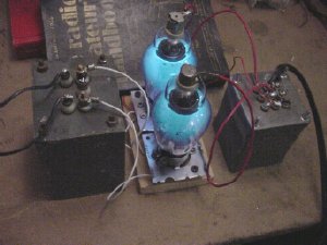
No switches were used on the test jig, I just plugged in the transfomers ONE at a TIME, Plug in the filaments FIRST.

Click to enlarge