 |
Click
for larger schematic
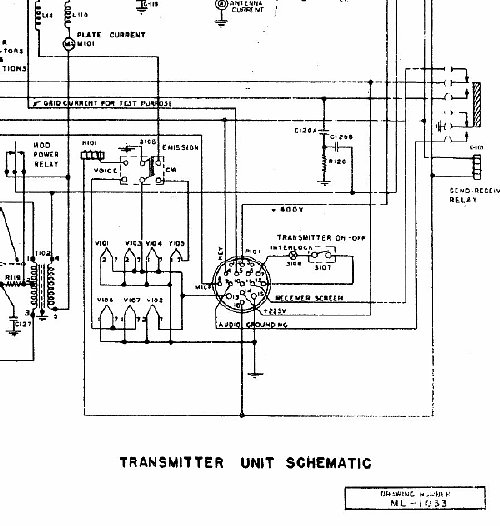
The TCS transmitter removes the 225
volts from the receiver tube screens during transmit with transmitter
relay K103 (via transmitter pins 11 and 14) and in addition the audio
line is grounded by the transmitter relay via transmitter connector pin
9.
Install a DPDT switch. One half of the switch
bypasses the transmitter relay input pins 11 and 14 and provides low B
plus direct to pin 3 on the receiver and the other half (but opposite
side) of the DPDT switch interrupts the audio path going to pin 9 of the
transmitter and prevents it from being grounded by K-103 during transmit.
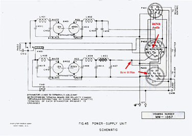
Arrows indicate areas that are effected by the DPDT switch.
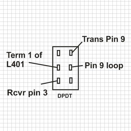
DPDT
Switch wiring rear view.
DPDT switch. Left side switches the
receiver screen voltage and is connected to Terminal 1 of L401 for convenience
and spot soldered to the receiver pin 3.(Pin 3 all ready has a wire on
it). Viewing the switch from the rear, the right side of the switch is
used to control the audio. When the transmitter is keyed the receiver
audio is normally grounded, you need to lift the wire from pin 9 on the
transmitter connector on the power supply and insert a switch between
pin 9 and the rest of the pin 9 loop wiring to the other connectors. Switch
ON to spot, switch OFF returns the set to normal amateur use.
Switch ON(up)connects 225 volts from
L401 direct to receiver pin 3 and overrides transmitter relay switching.
Switch OFF(down) restores normal transmit relay function and the screen
voltage will be removed from the receiver during transmit.
Switch ON (up) disconnects the audio
line from transmitter pin 9 and subsequent grounding of the audio line.
Switch down restores normal transmit relay function and during transmit
the audio is muted by grounding the line.
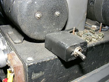
The
"Spot" switch mounted in a small enclosure and utilizes existing
hardware to
secure it to the chassis. A "No Holes" modification.
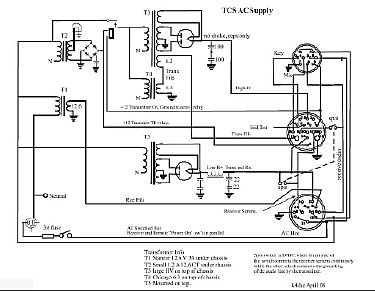
A spot switch was also added to my homebrew AC supply