SCR-284-A
Bench and Ops Notes. Repairs,
Test/break out boards, Modifications and power. And a lot of PE-104 info
presented.
INDEX Click to Navigate
Intro
Receiver Power - Bench power for the receiver.
Replacing
Capacitors - Do your self a favor and change all those postage stamps.
80
Meter Receiver Conversion - Lower 80 meter CW conversion.
BFO
Increased Injection - Better CW and SSBSC reception.
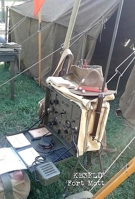
KB3ELD
- Dave's Fort Mott operating display.
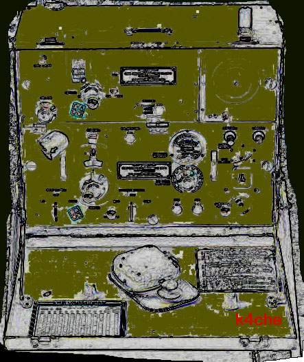
The BC-654 is a great set - Easy to recognize with the
classic fold down desk.
Dave
KB3ELD is our MRCA expert on the SCR-284.
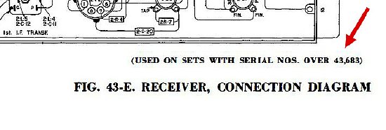
Most
of the schematics and drawings in TM-11-275 are arranged IAW serial numbers
of the sets.
When working
on the BC-654 if in doubt RTFM.
Reprints of TM 11-275 can be ordered at wa5cab.com. They are excellent reprints..
Receiver
Power Up
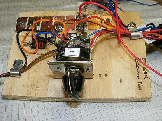
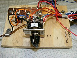
Receiver CW/ PHONE mode and power board.
I wanted to post this WARNING note but could not decide where to place it. Anyway here it is:
WARNING: Testing tubes: Do not test filament (continuity) with a analog VOM unless you are sure of the voltages applied during a resistance test. Normally you will use the low ranges of X1 and X10. My Simson 260 uses a 9 volt battery on the higher ranges of X10K!
CLICK
to enlarge
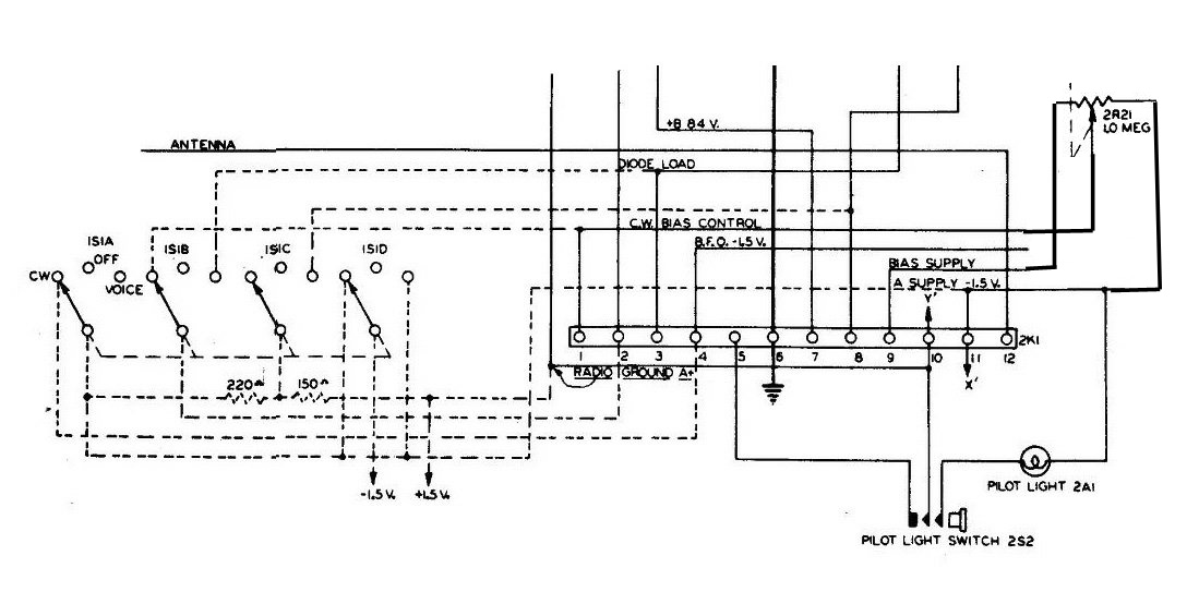
Dashed line
circuit above left represents the "Transmitter" control wiring
to control power and select CW/VOICE mode. Its easier to set up the receiver
on the bench by duplicating this dashed line circuit and build it up on
a small board and attaching to the main receiver terminal strip. A 4 pole
double pole rotary switch might be hard to find so just substitute a couple
of 2 pole double throw switches - or just use a alligator clip and nails
for contacts.
Don't omit the 150 and 220 ohm resistors.
Receiver Power up: 1.5V
- Minus to the dashed line circuit which feeds Terminal 11.
1.5
+ Pos to radio ground Terminal 10
B + to Terminal 7 of the receiver terminal
strip 2K1.
B - minus Terminal 10
Bias - minus Terminal 9 (Use a 9 volt
battery for testing with 1 K resistor.)
Bias + plus Terminal 10
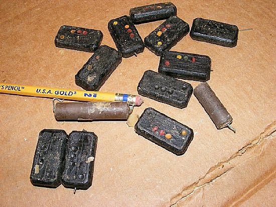
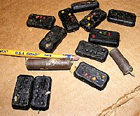
Replace
all "Postage Stamp" and tubular paper capacitors.
Do
your self a favor before working on the BC-654 receiver or transmitter.
Replace all the molded "Postage Stamp" capacitors and tubular
paper capacitors - Do them all - don't get
creative and decide which caps are critical - just dig in and replace
them. In the long run you will save time in achieving your goal of having
a working and reliable set. The purist restorer is probably not going
to be happy with this process but my mission is to have a working reliable
set for display at the next rally without spending a lifetime repairing
the set.
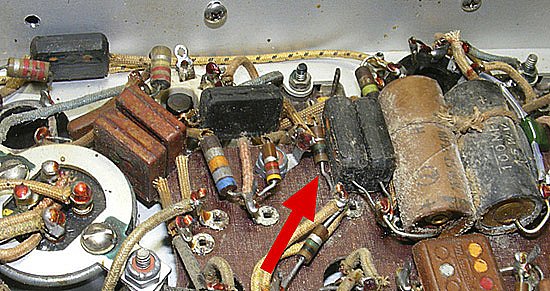
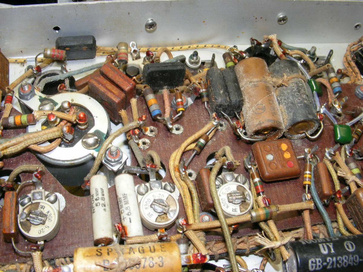
Its easy to spot the Postage Stamps as they are ugly. Also plan on replacing the large electrolytics. I found that 3 out of 10 Postage Stamps were obviously bad. All of the electrolytics in the receiver had gone South.
CLICK
to enlarge
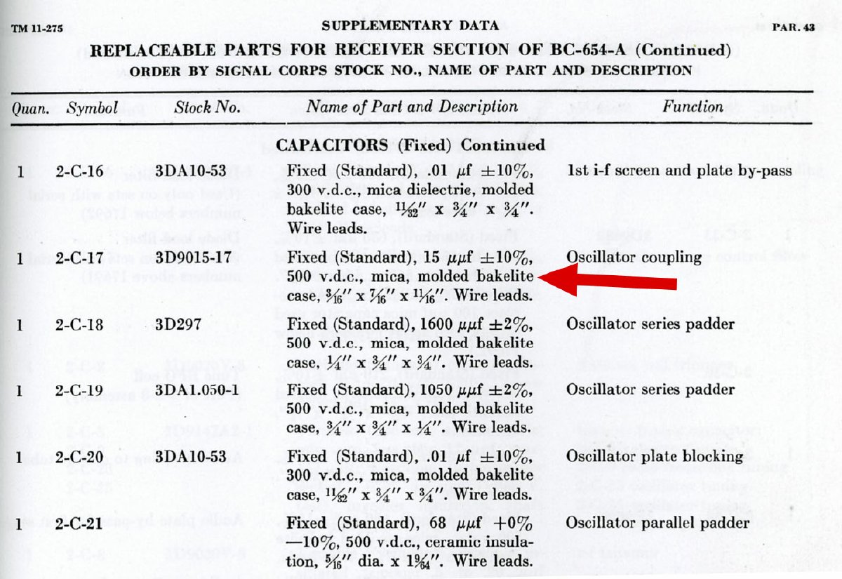
The
Parts List in the Supplementary Data section in TM 11-275 is excellent
and includes a "Function" column. You want to replace the "mica
molded bakelite case" capacitors.

Q. A lot of the capacitors listed in the receiver "Replaceable Parts" list are listed as 500 v.d.c but the actual "Tube Socket" voltages in the receiver are less than 100 volts. Do I need the 500 v.d.c. caps?
A. NO. You can examine each circuit in the receiver and often use caps that have a voltage rating less than listed but as a general rule I would go with a 200 volt rating or higher in the receiver and use the specified voltage ratings in the transmitter.
Q. How about voltage ratings for capacitors on the transmitter?
A.
You can examine each circuit but as a general rule I would go with the
voltages listed.

CLICK
to enlarge
Receiver Tubular Electrolytics
Also
check the "Tubular Electrolytics". On one receiver I found that
they were all bad.
There are only 4 Tubular Electrolytics in the Receiver
- Bad C-43 and C-45 Electrolytics can cause some interesting noises in
the receiver. Just change them and get with the project.
The same procedure is followed for the transmitter.
The
Receiver and Transmitter Chassis photos assist in locating parts but for
better detail of component boards etc. don't forget to check the "Connection
Diagrams" in the rear of the manual.
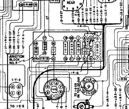
Connection
Diagram
The "Connection Diagrams" for the transmitter and receiver in the rear of the manual are a great aid in locating capacitors. Figures 43x and 45x depending on the serial number of your set.
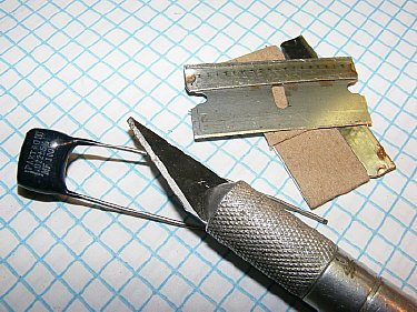
N3FRQ
photo( link below) - A tool for forming "pigtails"
on the replacement capacitors.
I prefer to just clip the leads on the old caps as close to the body as possible leaving the leads intact and then take the new replacement capacitor and form "Pigtails" on the leads and simply place the new "Pigtail" on the older leads - crimp slightly - and then solder. A very fast replacement process. But if you want to spend endless hours attempting to unsolder each capacitor connection and then during the process you break a lug on a tube socket or coil form you will not be happy so just do the pigtails and get on with the project.
More info on replacing
capacitors can be found at N3FRQ's web page.
http://www.skywaves.ar88.net/commrx/Maintenance/Comprepl/component_replacement.htm
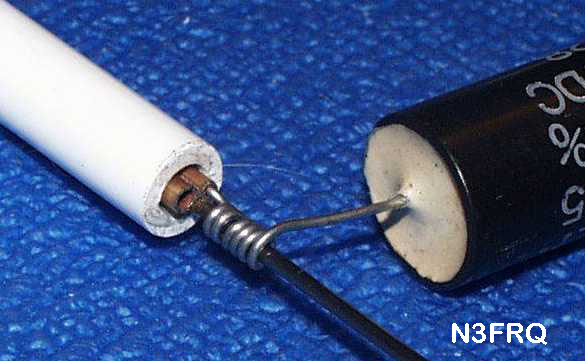
Scrape
and clean leads before forming the pig tails.
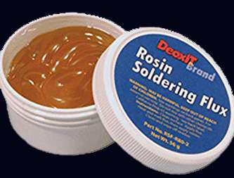
When soldering the leads use a very small amount of flux to ensure a good connection.
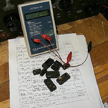
During the recap process stay organized. Make up a column chart with the Part # - Value - Circuit Function- resistance check - tested value of removed cap etc. Measuring and testing the cap after removal makes you feel good when you discover leaky or out of tolerance caps.
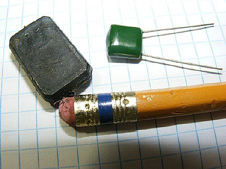
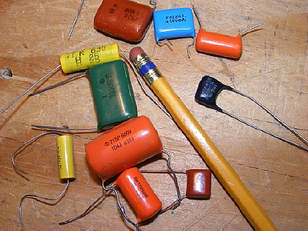
The
newer caps are available in a smaller package. Construction
of these caps is usually Metal-Foil Polypropylene or Metalized
Polypropylene Film what ever that means. You can easily obtain a capacitor
half the size of the original Postage Stamp and have a voltage rating
of 630 volts.
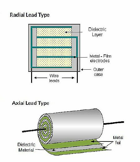
Photo
by electronics-tutorials.we/capacitor/cap
There is plenty of room in the receiver to allow installation of either radial or axial lead capacitors.
Both
radial leads and axial lead caps were used as they were available in my
capacitor box.
Here
are several links to suppliers:
https://www.tubesandmore.com/products/capacitors
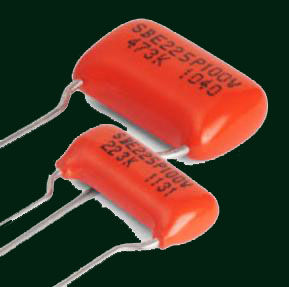
The latest fad is to use all "Orange Drop" capacitors. They are pretty color but expensive. Available in radial lead configuration only. They are available but you may have a hard time finding a source for all of the values needed in the receiver and transmitter. Just mix and match the capacitors and get on with the project.
HINT:
Confirm the value of the new cap before installation. Use the proper voltage
rating. A 100 volt rating could be used for replacement caps in the receiver
but I prefer to use 200 volts or higher. The transmitter requires higher
voltage ratings in the later stages. There are plenty of "digital"
capacitor testers available on ePay. Be careful
when measuring large value electrolytics with a digital tester - be sure
and complete discharge the capacitor first!
CLICK
to enlarge
Be sure
and replace C43 and C45 100 uF electrolytic. They are not Good and certainly
they are Bad and definitely Ugly. They are used as noise suppressers on
the filament line.
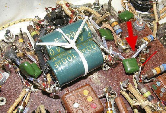
The new C43 and C45 100 uF replacements.
Plenty of room on the individual chassis boards and actual chassis for the new smaller size caps. The new electrolytics are also a lot smaller. Be sure and secure the large electrolytics with lacing. Don't forget to insulate the leads on all caps when necessary. I prefer Teflon spaghetti insulation available on ePay as it does not melt when soldering.
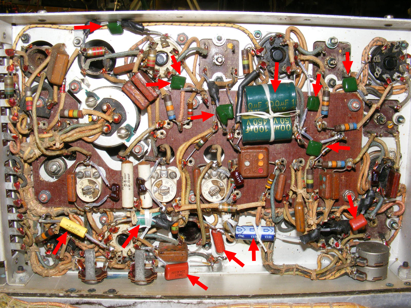
CLICK to enlarge
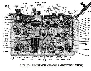
Receiver Chassis bottom view - arrows point to new capacitors. Most of the replacement capacitors had radial leads as they were available in my capacitor box.
![]()
CLICK
to enlarge
Transmitter
chassis with new caps. I may have missed arrows on one or two. Don't screw
around and waste time just go ahead and replace all of the paper capacitors.
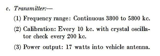
PROBLEM: The BC-654 receiver or transmitter frequency coverage does not include the lower end of 80 meters. The entire Extra Class Phone and CW segment are also not covered.
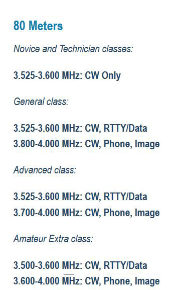
The BC-654 receiver or transmitter frequency coverage does not extend below 3800 Kcs. You are SOL if you want to operate 80 meter CW or use portions of the Extra Class segments.
Q: Will the dial markings
be accurate on the transmitter and receiver dial after the frequency modifications?
A:
No - you can make up a correction chart and/or use a label marker for
new dial markings.
Q: will the calibration
oscillator still operate every 200 kcs.
A: Yes
Q: Can the mods be easily reversed?
A: Yes - the modification caps can be tack soldered in place.
Q: Its is legal to operate CW in the phone portion of 75 meters.
A: Yes
Q: Will receiver sensitivity be effected?
A: No
Q: Will the transmitter power output be effected?
A: No

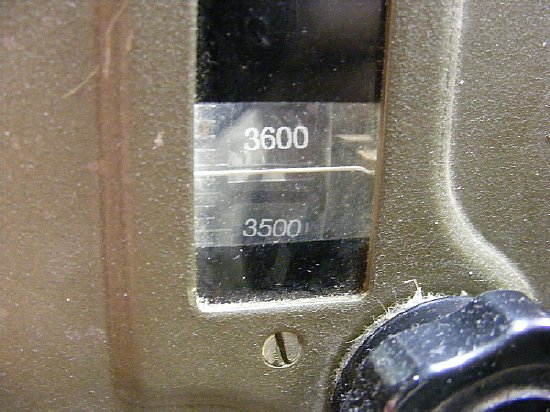
On
my receiver I extended the coverage down below 3.500 to cover NY VOLMET
on 3.485 Kc. It is a great site to demo reception of the USBSC on a WWII
receiver. Google VOLMET.

CLICK
to enlarge
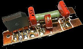
The receiver utilizes ceramic trimmers that are augmented with a fixed capacitor. Modifying the receiver for a lower frequency coverage can be accomplished by adding additional capacitance to the adjustable trimmer circuits to increase the "fixed" capacitance. The original trimmers will still function properly and can be used for alignment. There is a free lunch after all.
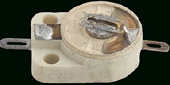
A typical ceramic trimmer capacitor.
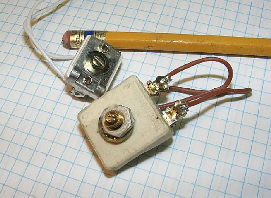
When experimenting with capacitors in RF circuits a handy device is an adjustable trimmer with wire leads. Temporarily install in the circuit and adjust the trimmer for best performance - then remove and measure the capacitance. Replace with a fixed capacitor.

CLICK
to enlarge
Lower frequency modification caps have been installed on trimmers 2C2 ( RF In) , 2C22 (Oscillator) , and 2C8 (Mixer In) . Trimmers can still be adjusted for alignment. I chose 3.5 and 4.6 Mc for alignment points.
Note: The modification values for the RF and Mixer sections were found by setting the antenna (2L1) and RF coil (2L2) about 5 turns from the bottom then setting the trimmers to approximately 1/2 capacitance and then experimenting with adding additional "fixed" capacitance to the receiver trimmers. After installing the additional "fixed" capacitors you can easily "touch up" the circuits on 75/80 meters by just using the antenna (2L1) and RF coil (2L3) adjustments accessible from the top of the receiver if necessary. Play with it - its not that complicated. The set tracks well across the 75/80 meter band and still functions well above 4.0 Mcs.
Labels can be added for the new frequency coverage. They can be removed.
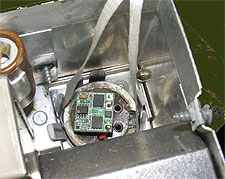
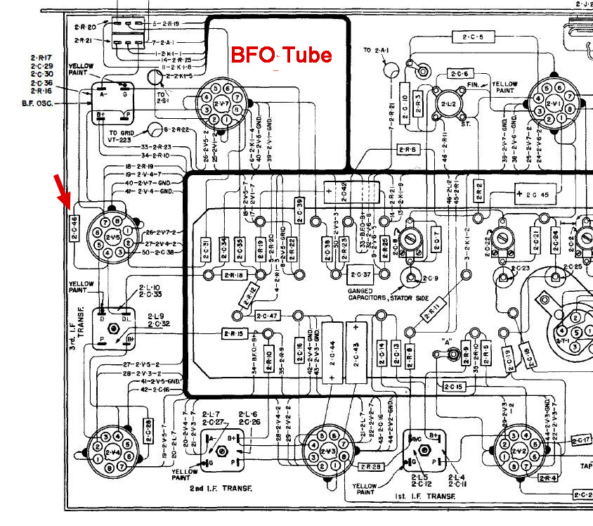
Problem: The BC-654 receiver usually lacks sufficient BFO injection to provide adequate CW reception. The injection level is easily improved with a reversible modification. The mod also lends itself to demonstrating the receiver on 75 Meter SSBSC or DSBSC.

CLICK to enlarge
Capacitor 2C46 a 4.7 pf is used to couple the BFO injection to the 3rd IF transformer. The value of 2C46 is usually too small in value for sufficient coupling and needs to be augmented with a larger value. Experiment with a 10 to 20 pF placed in parallel with 2C46.
CLICK to enlarge
2C46 is not mounted in the BFO tube area it is mounted on spare lugs 4 and 8 of socket 2V5. This places it at a convenient point between the BFO tube 2V7 and the 3rd IF 2L9/10 IF can.
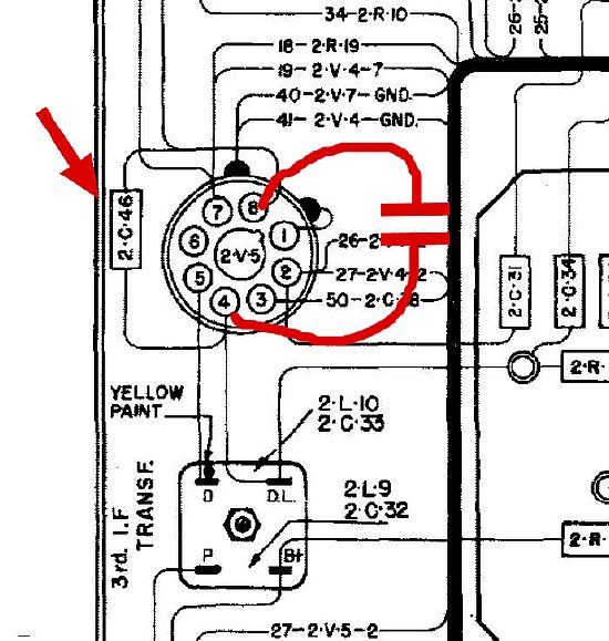
Solder
your additional capacitor across 2C46.
RETURN
to top of page.
Continue
with Page 2 (Under Construction) Transmitter, Battery, PE-104